2005 INFINITI FX35 ignition
[x] Cancel search: ignitionPage 546 of 4731

TROUBLE DIAGNOSIS ATC-109
C
D E
F
G H
I
K L
M A
B
AT C
Revision: 2005 July 2005 FX
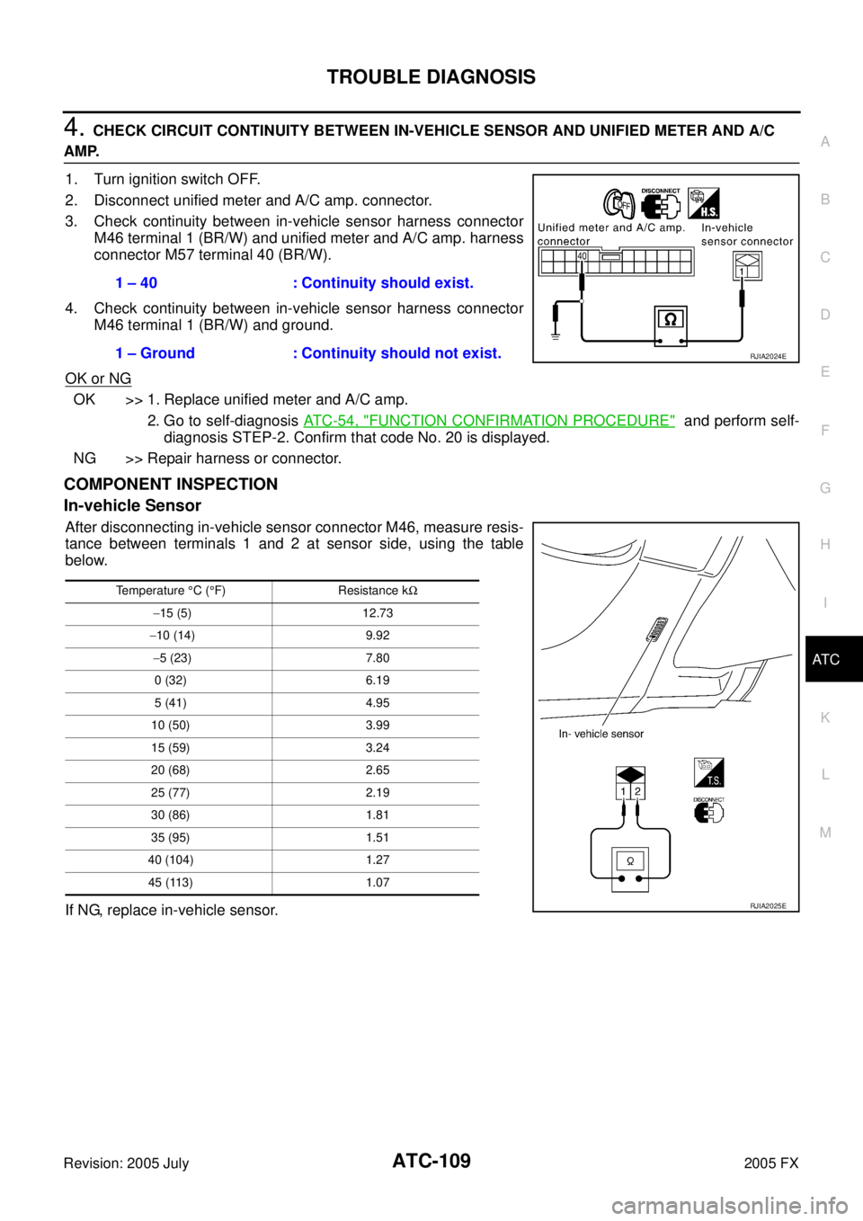
4. CHECK CIRCUIT CONTINUITY BETWEEN IN-VEHICLE SENSOR AND UNIFIED METER AND A/C
AMP.
1. Turn ignition switch OFF.
2. Disconnect unified meter and A/C amp. connector.
3. Check continuity between in-vehicle sensor harness connector M46 terminal 1 (BR/W) and unified meter and A/C amp. harness
connector M57 terminal 40 (BR/W).
4. Check continuity between in-vehicle sensor harness connector M46 terminal 1 (BR/W) and ground.
OK or NG
OK >> 1. Replace unified meter and A/C amp. 2. Go to self-diagnosis AT C - 5 4 , "
FUNCTION CONFIRMATION PROCEDURE" and perform self-
diagnosis STEP-2. Confirm that code No. 20 is displayed.
NG >> Repair harness or connector.
COMPONENT INSPECTION
In-vehicle Sensor
After disconnecting in-vehicle sensor connector M46, measure resis-
tance between terminals 1 and 2 at sensor side, using the table
below.
If NG, replace in-vehicle sensor. 1 – 40 : Continuity should exist.
1 – Ground : Continuity should not exist.
RJIA2024E
Temperature °C ( °F) Resistance k Ω
− 15 (5) 12.73
− 10 (14) 9.92
− 5 (23) 7.80
0 (32) 6.19
5 (41) 4.95
10 (50) 3.99
15 (59) 3.24
20 (68) 2.65
25 (77) 2.19
30 (86) 1.81
35 (95) 1.51
40 (104) 1.27 45 (113) 1.07
RJIA2025E
Page 547 of 4731

ATC-110
TROUBLE DIAGNOSIS
Revision: 2005 July 2005 FX
Sunload Sensor CircuitAJS00156
COMPONENT DESCRIPTION
Sunload Sensor
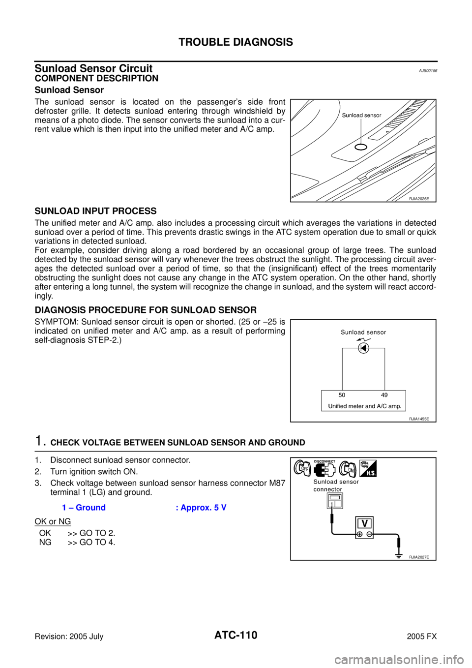
The sunload sensor is located on the passenger’s side front
defroster grille. It detects sunload entering through windshield by
means of a photo diode. The sensor converts the sunload into a cur-
rent value which is then input into the unified meter and A/C amp.
SUNLOAD INPUT PROCESS
The unified meter and A/C amp. also includes a processing circuit which averages the variations in detected
sunload over a period of time. This prevents drastic swings in the ATC system operation due to small or quick
variations in detected sunload.
For example, consider driving along a road bordered by an occasional group of large trees. The sunload
detected by the sunload sensor will vary whenever the trees obstruct the sunlight. The processing circuit aver-
ages the detected sunload over a period of time, so that the (insignificant) effect of the trees momentarily
obstructing the sunlight does not cause any change in the ATC system operation. On the other hand, shortly
after entering a long tunnel, the system will recognize the change in sunload, and the system will react accord-
ingly.
DIAGNOSIS PROCEDURE FOR SUNLOAD SENSOR
SYMPTOM: Sunload sensor circuit is open or shorted. (25 or −25 is
indicated on unified meter and A/C amp. as a result of performing
self-diagnosis STEP-2.)
1. CHECK VOLTAGE BETWEEN SUNLOAD SENSOR AND GROUND
1. Disconnect sunload sensor connector.
2. Turn ignition switch ON.
3. Check voltage between sunload sensor harness connector M87 terminal 1 (LG) and ground.
OK or NG
OK >> GO TO 2.
NG >> GO TO 4.
RJIA2026E
RJIA1455E
1 – Ground : Approx. 5 V
RJIA2027E
Page 548 of 4731

TROUBLE DIAGNOSIS ATC-111
C
D E
F
G H
I
K L
M A
B
AT C
Revision: 2005 July 2005 FX
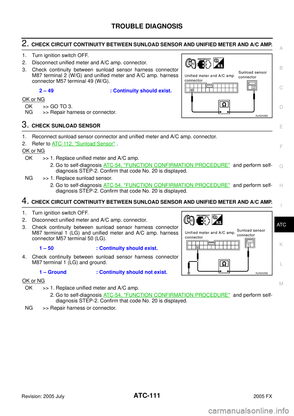
2. CHECK CIRCUIT CONTINUITY BETWEEN SUNLOAD SENSOR AND UNIFIED METER AND A/C AMP.
1. Turn ignition switch OFF.
2. Disconnect unified meter and A/C amp. connector.
3. Check continuity between sunload sensor harness connector M87 terminal 2 (W/G) and unified meter and A/C amp. harness
connector M57 terminal 49 (W/G).
OK or NG
OK >> GO TO 3.
NG >> Repair harness or connector.
3. CHECK SUNLOAD SENSOR
1. Reconnect sunload sensor connector and unified meter and A/C amp. connector.
2. Refer to AT C - 11 2 , "
Sunload Sensor" .
OK or NG
OK >> 1. Replace unified meter and A/C amp.
2. Go to self-diagnosis AT C - 5 4 , "
FUNCTION CONFIRMATION PROCEDURE" and perform self-
diagnosis STEP-2. Confirm that code No. 20 is displayed.
NG >> 1. Replace sunload sensor. 2. Go to self-diagnosis AT C - 5 4 , "
FUNCTION CONFIRMATION PROCEDURE" and perform self-
diagnosis STEP-2. Confirm that code No. 20 is displayed.
4. CHECK CIRCUIT CONTINUITY BETWEEN SUNLOAD SENSOR AND UNIFIED METER AND A/C AMP.
1. Turn ignition switch OFF.
2. Disconnect unified meter and A/C amp. connector.
3. Check continuity between sunload sensor harness connector M87 terminal 1 (LG) and unified meter and A/C amp. harness
connector M57 terminal 50 (LG).
4. Check continuity between sunload sensor harness connector M87 terminal 1 (LG) and ground.
OK or NG
OK >> 1. Replace unified meter and A/C amp. 2. Go to self-diagnosis AT C - 5 4 , "
FUNCTION CONFIRMATION PROCEDURE" and perform self-
diagnosis STEP-2. Confirm that code No. 20 is displayed.
NG >> Repair harness or connector. 2 – 49 : Continuity should exist.
RJIA2028E
1 – 50 : Continuity should exist.
1 – Ground : Continuity should not exist.
RJIA2029E
Page 550 of 4731

TROUBLE DIAGNOSIS ATC-113
C
D E
F
G H
I
K L
M A
B
AT C
Revision: 2005 July 2005 FX
Intake Sensor CircuitAJS00157
COMPONENT DESCRIPTION
Intake Sensor
The intake sensor is located on the heater & cooling unit assembly. It
converts temperature of air after it passes through the evaporator
into a resistance value which is then input to the unified meter and A/
C amp.
DIAGNOSIS PROCEDURE FOR INTAKE SENSOR
SYMPTOM: Intake sensor circuit is open or shorted. (24 or −24 is
indicated on unified meter and A/C amp. as a result of performing
self-diagnosis STEP-2.)
1. CHECK VOLTAGE BETWEEN INTAKE SENSOR AND GROUND
1. Disconnect intake sensor connector.
2. Turn ignition switch ON.
3. Check voltage between intake sensor harness connector M254 terminal 2 (R) and ground.
OK or NG
OK >> GO TO 2.
NG >> GO TO 4.
2. CHECK CIRCUIT CONTINUITY BETWEEN INTAKE SENSOR AND UNIFIED METER AND A/C AMP.
1. Turn ignition switch OFF.
2. Disconnect unified meter and A/C amp. connector.
3. Check continuity between intake sensor harness connector M254 terminal 1 (W) and unified meter and A/C amp. harness
connector M57 terminal 49 (W/G).
OK or NG
OK >> GO TO 3.
NG >> Repair harness or connector.
RJIA0928E
RJIA1458E
2 – Ground : Approx. 5 V
RJIA2031E
1 – 49 : Continuity should exist.
RJIA2032E
Page 551 of 4731

ATC-114
TROUBLE DIAGNOSIS
Revision: 2005 July 2005 FX
3. CHECK INTAKE SENSOR
Refer to AT C - 11 4 , "
Intake Sensor" .
OK or NG
OK >> 1. Replace unified meter and A/C amp. 2. Go to self-diagnosis AT C - 5 4 , "
FUNCTION CONFIRMATION PROCEDURE" and perform self-
diagnosis STEP-2. Confirm that code No. 20 is displayed.
NG >> 1. Replace intake sensor. 2. Go to self-diagnosis AT C - 5 4 , "
FUNCTION CONFIRMATION PROCEDURE" and perform self-
diagnosis STEP-2. Confirm that code No. 20 is displayed.
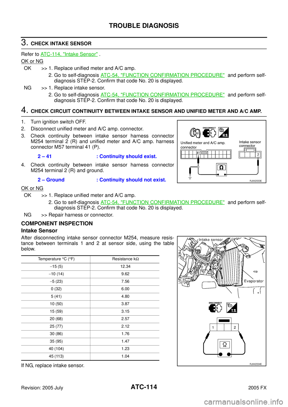
4. CHECK CIRCUIT CONTINUITY BETWEEN INTAKE SENSOR AND UNIFIED METER AND A/C AMP.
1. Turn ignition switch OFF.
2. Disconnect unified meter and A/C amp. connector.
3. Check continuity between intake sensor harness connector M254 terminal 2 (R) and unified meter and A/C amp. harness
connector M57 terminal 41 (P).
4. Check continuity between intake sensor harness connector M254 terminal 2 (R) and ground.
OK or NG
OK >> 1. Replace unified meter and A/C amp. 2. Go to self-diagnosis AT C - 5 4 , "
FUNCTION CONFIRMATION PROCEDURE" and perform self-
diagnosis STEP-2. Confirm that code No. 20 is displayed.
NG >> Repair harness or connector.
COMPONENT INSPECTION
Intake Sensor
After disconnecting intake sensor connector M254, measure resis-
tance between terminals 1 and 2 at sensor side, using the table
below.
If NG, replace intake sensor. 2 – 41 : Continuity should exist.
2 – Ground : Continuity should not exist.
RJIA2033E
Temperature °C ( °F) Resistance k Ω
− 15 (5) 12.34
− 10 (14) 9.62
− 5 (23) 7.56
0 (32) 6.00
5 (41) 4.80
10 (50) 3.87
15 (59) 3.15
20 (68) 2.57
25 (77) 2.12
30 (86) 1.76
35 (95) 1.47
40 (104) 1.23 45 (113) 1.04
RJIA2034E
Page 599 of 4731

ATC-162
SERVICE DATA AND SPECIFICATIONS (SDS)
Revision: 2005 July 2005 FX
SERVICE DATA AND SPECIFICATIONS (SDS)PFP:00030
CompressorAJS00167
LubricantAJS00168
RefrigerantAJS00169
Engine Idling SpeedAJS0016A
Refer to EC-83, "Idle Speed and Ignition Timing Check" (VQ35DE) or EC-774, "Idle Speed and Ignition Tim-
ing Check" (VK45DE).
Belt TensionAJS0016B
Refer to EM-15, "DRIVE BELTS" (VQ35DE) or EM-173, "DRIVE BELTS" (VK45DE).
Model Calsonic Kansei make CWV-618
Ty p e V-6 variable displacement
Displacement
cm
3 (cu in)/rev Max. 184 (11.228)
Min. 14.5 (0.885)
Cylinder bore × stroke
mm (in) 37 (1.46)
× [2.3 - 28.6 (0.091 - 1.126)]
Direction of rotation Clockwise (viewed from drive end)
Drive belt Poly V
ModelCalsonic Kansei make CWV-618
Name Nissan A/C System Oil Type S (DH-PS)
Part number KLH00-PAGS0
Capacity
m (US fl oz, lmp fl oz) Total in system 180 (6.0, 6.3)
Compressor (Service part) charg-
ing amount 180 (6.0, 6.3)
Ty p e
HFC-134a (R-134a)
Capacity
kg (lb) 0.55 (1.21)
Page 601 of 4731

AV-2Revision: 2005 July 2005 FX
Window Antenna Repair ......................................
... 54
CHECK ELEMENT ........................................... ... 54
Removal and Installation of Roof Antenna .......... ... 56
REMOVAL ........................................................ ... 56
INSTALLATION ................................................. ... 56
INTEGRATED DISPLAY SYSTEM ......................... ... 57
System Description .............................................. ... 57
A/C AND AV SWITCH SYSTEM ....................... ... 57
PRECAUTION OF LCD MONITOR .................. ... 57
POWER SUPPLY AND GROUND .................... ... 57
DRIVE COMPUTER ......................................... ... 58
E/M SWITCH .................................................... ... 59
SETTING SCREEN .......................................... ... 60
WARNING INDICATIONS ................................ ... 61
AV COMMUNICATION LINE ............................ ... 61
CAN Communication System Description ........... ... 61
CAN Communication Unit .................................... ... 61
Component Parts and Harness Connector Location ... 61
Schematic ............................................................ ... 62
Wiring Diagram — INF/D — ................................ ... 63
Schematic ............................................................ ... 68
Wiring Diagram — COMM — .............................. ... 69
Terminals and Reference Value for Display Unit . ... 72
Terminals and Reference Value for A/C and AV
Switch .................................................................. ... 73
On Board Self-Diagnosis Function ...................... ... 74
DESCRIPTION ................................................. ... 74
DIAGNOSIS ITEM ............................................ ... 74
Self-Diagnosis Mode ........................................... ... 74
OPERATION PROCEDURES .......................... ... 74
NETWORK CHECK .......................................... ... 75
PARTS CHECK ................................................ ... 75
HVAC DETAIL SCREEN ................................... ... 76
VERSION CHECK ............................................ ... 76
CAN DIAG MNTR (CAN DIAG MONITOR) ...... ... 76
A/C and AV Switch Self-Diagnosis Function ........ ... 77
STARTING THE SELF-DIAGNOSIS MODE ..... ... 77
EXITING THE SELF-DIAGNOSIS MODE ........ ... 77
DIAGNOSIS FUNCTION .................................. ... 77
Trouble Diagnosis Chart by Symptom ................. ... 78
Power Supply and Ground Circuit Check for Display
Unit ...................................................................... ... 79
Power Supply and Ground Circuit Check for A/C and
AV Switch ............................................................. ... 80
Vehicle Speed Signal Inspection ......................... ... 80
Illumination Signal Inspection .............................. ... 81
Ignition Signal Inspection ..................................... ... 82
Audio Communication Line Inspection ................ ... 82
AV Communication Line Inspection ..................... ... 84
CAN Communication Line Inspection .................. ... 85
Audio Steering Wheel Switch Inspection ............. ... 86
Removal and Installation of Display ..................... ... 86
REMOVAL ........................................................ ... 86
INSTALLATION ................................................. ... 86
Removal and Installation of A/C and AV Switch .. ... 86
NAVIGATION SYSTEM .......................................... ... 87
System Description .............................................. ... 87
TRAVEL DISTANCE ......................................... ... 87
TRAVEL DIRECTION ....................................... ... 87 MAP-MATCHING ..............................................
... 87
GPS (GLOBAL POSITIONING SYSTEM) ........ ... 88
COMPONENT DESCRIPTION ......................... ... 89
BIRDVIEW™ ..................................................... ... 89
MAP DISPLAY .................................................. ... 90
FUNCTION OF CENTER SWITCH .................. ... 91
“VIEW” MODE ................................................... ... 97
“HEADING” MODE ........................................... ... 98
“NEARBY DISPLAY ICONS” MODE ................. ... 98
“SAVE CURRENT LOCATION” MODE ............. ... 98
“ADJUST CURRENT LOCATION” MODE ........ ... 98
“AUTO RE-ROUTE” MODE .............................. ... 99
“AVOID AREA SETTING” MODE ..................... ... 99
“CLEAR MEMORY” MODE ............................... ... 99
“EDIT ADDRESS BOOK” MODE ...................... .100
“GPS INFORMATION” MODE .......................... .100
“QUICK STOP CUSTOMER SETTING” MODE .100
“SET AVERAGE SPEED” MODE ..................... .100
“TRACKING” MODE ......................................... .101
GUIDANCE VOLUME ....................................... .101
DISPLAY WITH PUSHED “TRIP” BUTTON ...... .101
TRIP 1 OR TRIP 2 ............................................ .102
FUEL ECONOMY ............................................. .102
MAINTENANCE ................................................ .102
ENGINE OIL OR TIRE ROTATION ................... .102
TIRE PRESSURE ............................................. .103
WARNING INDICATIONS ................................. .103
CAN Communication System Description ........... .104
CAN Communication Unit .................................... .104
Component Parts Location and Harness Connector
Location ............................................................... .104
Schematic—NAVI— ............................................. .105
Wiring Diagram —NAVI— .................................... .106
Schematic — COMM — ....................................... .113
Wiring Diagram — COMM — ............................... .114
Terminals and Reference Value for NAVI Control
Unit ....................................................................... .119
Terminals and Reference Value for Display Control
Unit ....................................................................... .121
Terminals and Reference Value for Display ......... .125
Terminals and Reference Value for A/C and AV
Switch .................................................................. .127
On Board Self-Diagnosis Function ....................... .128
DESCRIPTION ................................................. .128
DIAGNOSIS ITEM ............................................ .128
Self-Diagnosis Mode (DCU) ................................. .129
OPERATION PROCEDURE ............................. .129
SELF–DIAGNOSIS RESULT ............................ .130
Self-Diagnosis Mode (NAVI) ................................ .131
OPERATION PROCEDURE ............................. .131
SELF–DIAGNOSIS RESULT ............................ .132
Confirmation/Adjustment Mode ............................ .133
OPERATION PROCEDURE ............................. .133
DISPLAY DIAGNOSIS ...................................... .134
VEHICLE SIGNALS .......................................... .134
AUTO CLIMATE CONTROL ............................. .135
NAVIGATION .................................................... .135
DISPLAY DIAGNOSIS ...................................... .135
VEHICLE SIGNALS .......................................... .136
Page 602 of 4731

AV-3
C
D E
F
G H
I
J
L
M A
B
AV
Revision: 2005 July 2005 FX
HISTORY OF ERRORS ...................................
. 136
DIAGNOSIS BY HISTORY OF ERRORS ........ . 137
NAVIGATION ................................................... . 138
CAN Diag Support Monitor .................................. . 140
OPERATION PROCEDURE ............................ . 140
A/C and AV Switch Self-Diagnosis Function ....... . 141
DESCRIPTION ................................................. . 141
Power Supply and Ground Circuit Check for NAVI
Control Unit ......................................................... . 142
Power Supply and Ground Circuit Check for Display
Control Unit ......................................................... . 143
Power Supply and Ground Circuit Check for Display . 144
Power Supply and Ground Circuit Check for A/C and
AV Switch ............................................................ . 145
Vehicle Speed Signal Check for NAVI Control Unit . 145
Vehicle Speed Signal Check for Display Control Unit . 146
Illumination Signal Check for NAVI Control Unit .. . 147
Illumination Signal Check for Display Control Unit . 148
Ignition Signal Check for NAVI Control Unit ........ . 148
Ignition Signal Check for Display Control Unit .... . 148
Reverse Signal Check for NAVI Control Unit ...... . 148
Reverse Signal Check for Display Control Unit ... . 149
AV Communication Line Check (Between Display
Control Unit and NAVI Control Unit) .................... . 149
Audio Communication Line Check (Between Dis-
play Control Unit and Audio Unit) ........................ . 150
Display Communication Line Check (Between Dis-
play Control Unit and Display) ............................. . 152
AV Communication Line Check (Between Display
Control Unit and A/C and AV Switch) .................. . 154
CAN Communication Line Check ........................ . 155
If NAVI Control Unit Detects That DVD-ROM Map
Is Not Inserted ..................................................... . 155
If NAVI Control Unit Detects That Inserted DVD-
ROM Map Malfunctioning Or If It Is Impossible to
Load Data from DVD-ROM Map ......................... . 155
If Connection Between NAVI Control Unit and GPS
AntennaIs Malfunctioning .................................... . 156
RGB Screen Is Not Shown .................................. . 156
Color of RGB Image Is Not Proper (NAVI Screen
Looks Bluish) ....................................................... . 157
Color of RGB Image Is Not Proper (NAVI Screen
Looks Reddish) ................................................... . 158
Color of RGB Image Is Not Proper (NAVI Screen
Looks Yellowish) .................................................. . 159
Color of RGB Image Is Not Proper (All Screens
Looks Bluish) ....................................................... . 160
Color of RGB ImageIs Not Proper (All Screens
Looks Reddish) ................................................... . 161
Color of RGB Image Is Not Proper (All Screens
Looks Yellowish) .................................................. . 162
RGB Screen Is Rolling (NAVI Screen) ................ . 163
RGB Screen Is Rolling (Excepting NAVI Screen) . 164
Guide Sound Is Not Heard .................................. . 165
Screen Is Not Shown .......................................... . 166
Audio Screen Is Not Shown (NAVI Screen Is Shown) . 166
A/C Screen Is Not Shown (NAVI Screen Is Shown) . 166
TRIP, FUEL ECON and MAINTENANCE Screens
Are Not Shown .................................................... . 166 Average Fuel Economy Displayed Is Not Shown . 167
Driving Distance or Average Speed Displayed Is Not
Shown .................................................................. .167
WARNING DOOR OPEN Screen Is Not Shown .. .168
Tire Pressure Is Not Displayed ............................ .168
Unable to Operate All of A/C and AV Switch (Unable
to Start Self-Diagnosis) ........................................ .168
Navigation System Does Not Activate ................. .169
Position of Current-Location Mark Is Not Correct . 169
Driving Test .......................................................... .170
Example of Symptoms Judged Not Malfunction .. .171
BASIC OPERATION ......................................... .171
VEHICLE MARK ............................................... .171
DESTINATION, PASSING POINTS, AND MENU
ITEMS CANNOT BE SELECTED/SET ............. .172
VOICE GUIDE .................................................. .172
ROUTE SEARCH ............................................. .172
EXAMPLES OF CURRENT-LOCATION MARK
DISPLACEMENT ............................................. .174
CURRENT LOCATION MARK SHOWS A POSI-
TION WHICH IS COMPLETELY WRONG ....... .177
CURRENT-LOCATION MARK JUMPS ............ .177
CURRENT LOCATION MARK IS IN A RIVER OR
SEA .................................................................. .178
WHEN DRIVING ON SAME ROAD, SOME-
TIMES CURRENT-LOCATION MARK IS IN
RIGHT PLACE AND SOMETIMES IT IS WRONG
PLACE .............................................................. .178
LOCATION CORRECTION BY MAP-MATCH-
ING IS SLOW ................................................... .178
ALTHOUGH GPS RECEIVING DISPLAY IS
GREEN, VEHICLE MARK DOES NOT RETURN
TO CORRECT LOCATION ............................... .178
NAME OF CURRENT PLACE IS NOT DIS-
PLAYED ............................................................ .178
CONTENTS OF DISPLAY DIFFER FOR BIRD-
VIEW™ AND THE (FLAT) MAP SCREEN ....... .178
Program Loading of NAVI Control Unit ................ .179
Removal and Installation of NAVI Control Unit .... .180
REMOVAL ........................................................ .180
INSTALLATION ................................................ .180
Removal and Installation of GPS Antenna .......... .180
REMOVAL ........................................................ .180
INSTALLATION ................................................ .180
Removal and Installation of A/C and AV Switch .. .181
Removal and Installation of Display Unit ............. .181
Removal and Installation of Display Control Unit . 181 REMOVAL ........................................................ .181
INSTALLATION ................................................ .181
INFINITI MOBILE ENTERTAINMENT SYSTEM .... .182
System Description .............................................. .182
Component Parts and Harness Connector Location .183
Wiring Diagram – MES – ..................................... .184
Terminals and Reference Value for DVD Player .. .186
Terminals and Reference Value for DVD Display . 187
DVD Player Does Not Work ................................ .189
Screen Is Not Shown (While Sounds Come Out of
an Audio Speaker, Did Not Do of a Head Phone) .191
Screen Is not Shown (Sounds Come Out of Both