Page 502 of 4731

TROUBLE DIAGNOSIS ATC-65
C
D E
F
G H
I
K L
M A
B
AT C
Revision: 2005 July 2005 FX
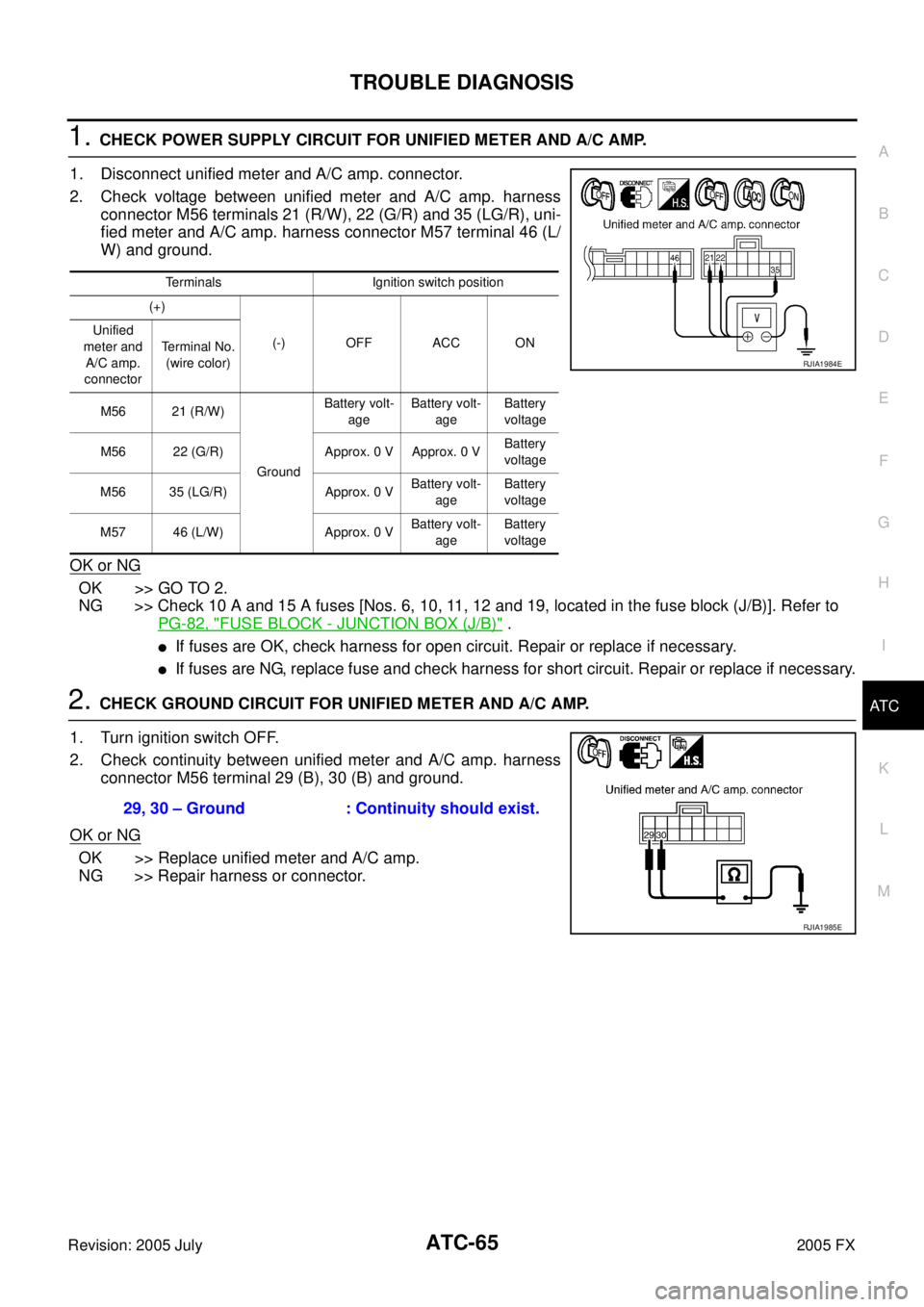
1. CHECK POWER SUPPLY CIRCUIT FOR UNIFIED METER AND A/C AMP.
1. Disconnect unified meter and A/C amp. connector.
2. Check voltage between unified meter and A/C amp. harness connector M56 terminals 21 (R/W), 22 (G/R) and 35 (LG/R), uni-
fied meter and A/C amp. harness connector M57 terminal 46 (L/
W) and ground.
OK or NG
OK >> GO TO 2.
NG >> Check 10 A and 15 A fuses [Nos. 6, 10, 11, 12 and 19, located in the fuse block (J/B)]. Refer to
PG-82, "
FUSE BLOCK - JUNCTION BOX (J/B)" .
�If fuses are OK, check harness for open circuit. Repair or replace if necessary.
�If fuses are NG, replace fuse and check harness for short circuit. Repair or replace if necessary.
2. CHECK GROUND CIRCUIT FOR UNIFIED METER AND A/C AMP.
1. Turn ignition switch OFF.
2. Check continuity between unified meter and A/C amp. harness connector M56 terminal 29 (B), 30 (B) and ground.
OK or NG
OK >> Replace unified meter and A/C amp.
NG >> Repair harness or connector.
Terminals Ignition switch position
(+)
(-) OFF ACC ON
Unified
meter and A/C amp.
connector Terminal No.
(wire color)
M56 21 (R/W)
Ground Battery volt-
age Battery volt-
age Battery
voltage
M56 22 (G/R) Approx. 0 V Approx. 0 V Battery
voltage
M56 35 (LG/R) Approx. 0 V Battery volt-
age Battery
voltage
M57 46 (L/W) Approx. 0 V Battery volt-
age Battery
voltage
RJIA1984E
29, 30 – Ground : Continuity should exist.
RJIA1985E
Page 503 of 4731
ATC-66
TROUBLE DIAGNOSIS
Revision: 2005 July 2005 FX
LAN System CircuitAJS0014S
SYMPTOM: Mode door motor, intake door motor and/or air mix door motor(s) does not operate normally.
DIAGNOSIS PROCEDURE FOR LAN CIRCUIT
1. CHECK POWER SUPPLY FOR UNIFIED METER AND A/C AMP.
1. Turn ignition switch ON.
2. Check voltage between unified meter and A/C amp. harness connector M57 terminal 54 (Y/R) and ground.
OK or NG
OK >> GO TO 2.
NG >> Replace unified meter and A/C amp.
2. CHECK SIGNAL FOR UNIFIED METER AND A/C AMP.
Confirm A/C LAN signal between unified meter and A/C amp. har-
ness connector M57 terminal 43 (G/B) and ground using an oscillo-
scope.
OK or NG
OK >> GO TO 3.
NG >> Replace unified meter and A/C amp.
RJIA1775E
54 – Ground : Battery voltage
RJIA1986E
Terminals
Voltage
(+)
( − )
Unified meter and A/
C amp. connector Terminal No.
(wire color)
M57 43 (G/B) Ground
RJIA1987E
HAK0652D
Page 504 of 4731

TROUBLE DIAGNOSIS ATC-67
C
D E
F
G H
I
K L
M A
B
AT C
Revision: 2005 July 2005 FX
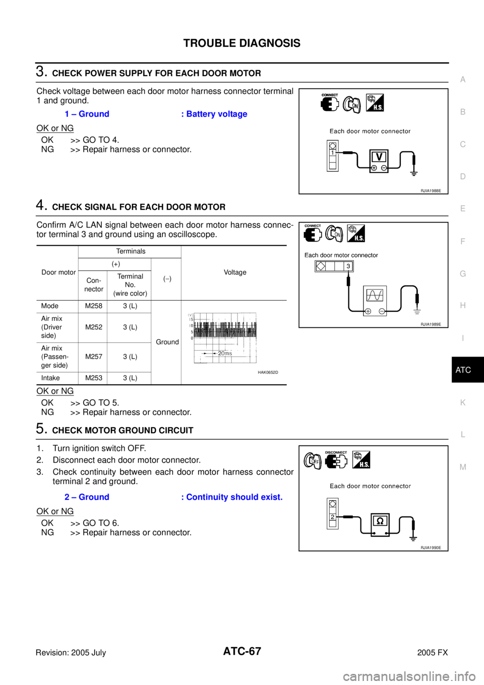
3. CHECK POWER SUPPLY FOR EACH DOOR MOTOR
Check voltage between each door motor harness connector terminal
1 and ground.
OK or NG
OK >> GO TO 4.
NG >> Repair harness or connector.
4. CHECK SIGNAL FOR EACH DOOR MOTOR
Confirm A/C LAN signal between each door motor harness connec-
tor terminal 3 and ground using an oscilloscope.
OK or NG
OK >> GO TO 5.
NG >> Repair harness or connector.
5. CHECK MOTOR GROUND CIRCUIT
1. Turn ignition switch OFF.
2. Disconnect each door motor connector.
3. Check continuity between each door motor harness connector terminal 2 and ground.
OK or NG
OK >> GO TO 6.
NG >> Repair harness or connector. 1 – Ground : Battery voltage
RJIA1988E
Door motor
Terminals
Voltage
(+)
( − )
Con-
nector Terminal
No.
(wire color)
Mode M258 3 (L)
Ground
Air mix
(Driver
side) M252 3 (L)
Air mix
(Passen-
ger side) M257 3 (L)
Intake M253 3 (L)
RJIA1989E
HAK0652D
2 – Ground : Continuity should exist.
RJIA1990E
Page 505 of 4731

ATC-68
TROUBLE DIAGNOSIS
Revision: 2005 July 2005 FX
6. CHECK MOTOR OPERATION
1. Turn ignition switch OFF.
2. Disconnect each door motor connector.
3. Reconnect each door motor connector.
4. Turn ignition switch ON.
5. Confirm operation of each door motor.
OK or NG
OK >> (Return to operate normally.)
�Poor contact in motor connector.
NG >> (Does not operate normally.)
�GO TO 7.
7. CHECK OPERATION OF AIR MIX DOOR MOTOR AND INTAKE DOOR MOTOR
1. Turn ignition switch OFF.
2. Disconnect mode, air mix (driver side, passenger side), and intake door motor connectors.
3. Reconnect air mix (driver side, passenger side) and intake door motor connectors.
4. Turn ignition switch ON.
5. Confirm operation of air mix door motor (driver side, passenger side) and intake door motor.
OK or NG
OK >> [Air mix (driver side, passenger side) and intake door motors operate normally.]
�Replace mode door motor.
NG >> [Air mix (driver side, passenger side) and intake door motors does not operate normally.]
�GO TO 8.
8. CHECK OPERATION OF MODE DOOR MOTOR AND INTAKE DOOR MOTOR
1. Turn ignition switch OFF.
2. Disconnect air mix door motor (driver side, passenger side) connectors.
3. Reconnect mode door motor connector.
4. Turn ignition switch ON.
5. Confirm operation of mode door motor and intake door motor.
OK or NG
OK >> (Mode and intake door motors operate normally.)
�GO TO 10.
NG >> (Mode and intake door motors does not operate normally.)
�GO TO 9.
9. CHECK OPERATION OF MODE DOOR MOTOR AND AIR MIX DOOR MOTOR
1. Turn ignition switch OFF.
2. Disconnect intake door motor connector.
3. Reconnect air mix door motor (driver side, passenger side) connectors.
4. Turn ignition switch ON.
5. Confirm operation of mode door motor and air mix door motor (driver side, passenger side).
OK or NG
OK >> [Mode and air mix door motor (driver side, passenger side) operate normally.]
�Replace intake door motor.
NG >> [Mode and air mix door motor (driver side, passenger side) does not operate normally.]
�Replace display and A/C auto amp.
Page 506 of 4731
TROUBLE DIAGNOSIS ATC-69
C
D E
F
G H
I
K L
M A
B
AT C
Revision: 2005 July 2005 FX
10. CHECK OPERATION OF AIR MIX DOOR MOTOR
1. Turn ignition switch OFF.
2. Disconnect air mix door motor (driver side) connector.
3. Turn ignition switch ON.
4. Confirm operation of air mix door motor (passenger side).
OK or NG
OK >> [Air mix door motor (passenger side) operates normally.]
�Replace air mix door motor (driver side).
NG >> [Air mix door motor (passenger side) does not operate normally.]
�Replace air mix door motor (passenger side).
Page 519 of 4731

ATC-82
TROUBLE DIAGNOSIS
Revision: 2005 July 2005 FX
1. CHECK POWER SUPPLY FOR BLOWER MOTOR
1. Disconnect blower motor connector.
2. Turn ignition switch ON.
3. Check voltage between blower motor harness connector M78 terminal 1 (L/W) and ground.
OK or NG
OK >> GO TO 2.
NG >> Check power supply circuit and 15 A fuses [Nos. 10 and 11, located in the fuse block (J/B)]. Refer to PG-82,
"FUSE BLOCK - JUNCTION BOX (J/B)" .
�If fuses are OK, check harness for open circuit. Repair or replace if necessary.
�If fuses are NG, replace fuse and check harness for short circuit. Repair or replace if necessary.
2. CHECK BLOWER MOTOR GROUND CIRCUIT
1. Turn ignition switch OFF.
2. Check continuity between blower motor harness connector M78 terminal 3 (B) and ground.
OK or NG
OK >> GO TO 3.
NG >> Repair harness or connector.
3. CHECK CIRCUIT CONTINUITY BETWEEN BLOWER MOTOR AND UNIFIED METER AND A/C AMP.
1. Disconnect unified meter and A/C amp. connector.
2. Check continuity between blower motor harness connector M78 terminal 2 (G) and unified meter and A/C amp. harness connec-
tor M57 terminal 53 (G).
OK or NG
OK >> GO TO 4.
NG >> Repair harness or connector. 1 – Ground : Battery voltage
RJIA1997E
3 – Ground : Continuity should exist.
RJIA1998E
2 – 53 : Continuity should exist.
RJIA1999E
Page 520 of 4731
TROUBLE DIAGNOSIS ATC-83
C
D E
F
G H
I
K L
M A
B
AT C
Revision: 2005 July 2005 FX
4. CHECK UNIFIED METER AND A/C AMP. OUTPUT SIGNAL
1. Reconnect blower motor connector and unified meter and A/C amp. connector.
2. Turn ignition switch ON.
3. Change the fan speed from Lo to Hi, and check the duty ratios between blower motor harness connector M78 terminal 2 (G) and ground using an oscilloscope. Normal terminal 2 (G) drive signal duty ratios are
shown in the table below.
OK or NG
OK >> Replace blower motor after confirming the fan air flow does not change.
NG >> Replace unified meter and A/C amp.
COMPONENT INSPECTION
Blower Motor
Confirm smooth rotation of the blower motor.
�Ensure that there are no foreign particles inside the blower unit.
RJIA2000E
RJIA2001E
RJIA0905E
Page 523 of 4731

ATC-86
TROUBLE DIAGNOSIS
Revision: 2005 July 2005 FX
1. CHECK AMBIENT SENSOR AND INTAKE SENSOR CIRCUIT
Check ambient sensor and intake sensor. Refer to AT C - 5 4 , "
FUNCTION CONFIRMATION PROCEDURE" ,
see No. 9 and 11.
OK or NG
OK >> GO TO 2.
NG >>
�Malfunctioning ambient sensor: Refer to ATC-104, "Ambient Sensor Circuit" .
�Malfunctioning intake sensor: Refer to AT C - 11 3 , "Intake Sensor Circuit" .
2. PERFORM AUTO ACTIVE TEST
Refer to PG-24, "
Auto Active Test" .
Does the magnet clutch operate?
YES >>�WITH CONSULT-II
GO TO 5.
�WITHOUT CONSULT-II
GO TO 6.
NO >> Check 10 A fuse (No. 79, located in IPDM E/R), and GO TO 3.
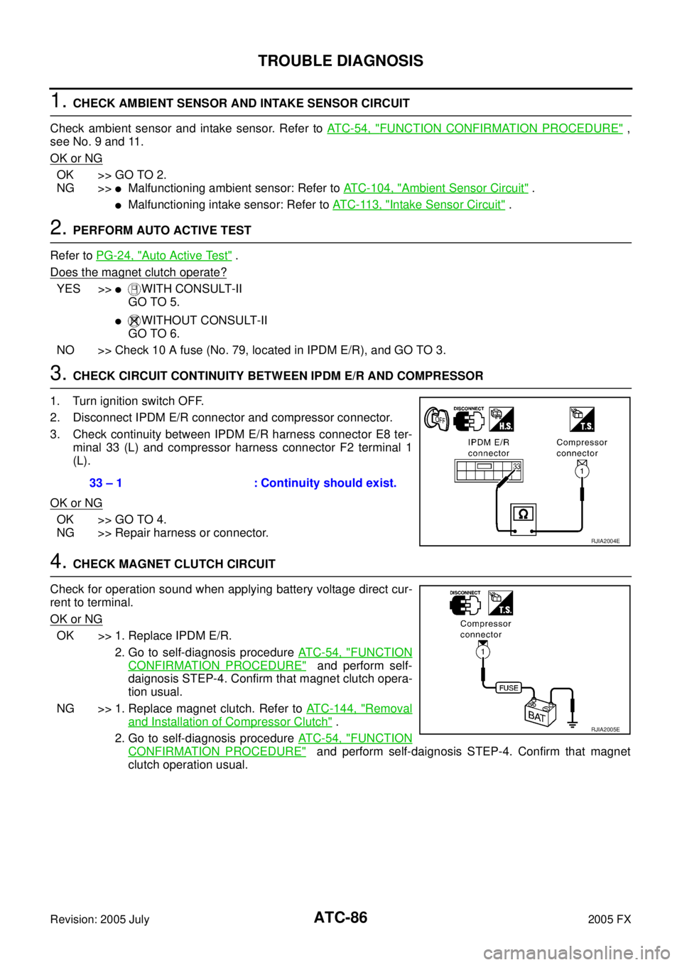
3. CHECK CIRCUIT CONTINUITY BETWEEN IPDM E/R AND COMPRESSOR
1. Turn ignition switch OFF.
2. Disconnect IPDM E/R connector and compressor connector.
3. Check continuity between IPDM E/R harness connector E8 ter- minal 33 (L) and compressor harness connector F2 terminal 1
(L).
OK or NG
OK >> GO TO 4.
NG >> Repair harness or connector.
4. CHECK MAGNET CLUTCH CIRCUIT
Check for operation sound when applying battery voltage direct cur-
rent to terminal.
OK or NG
OK >> 1. Replace IPDM E/R. 2. Go to self-diagnosis procedure AT C - 5 4 , "
FUNCTION
CONFIRMATION PROCEDURE" and perform self-
daignosis STEP-4. Confirm that magnet clutch opera-
tion usual.
NG >> 1. Replace magnet clutch. Refer to ATC-144, "
Removal
and Installation of Compressor Clutch" .
2. Go to self-diagnosis procedure AT C - 5 4 , "
FUNCTION
CONFIRMATION PROCEDURE" and perform self-daignosis STEP-4. Confirm that magnet
clutch operation usual.
33 – 1 : Continuity should exist.
RJIA2004E
RJIA2005E