Page 642 of 4731

AUDIO AV-43
C
D E
F
G H
I
J
L
M A
B
AV
Revision: 2005 July 2005 FX
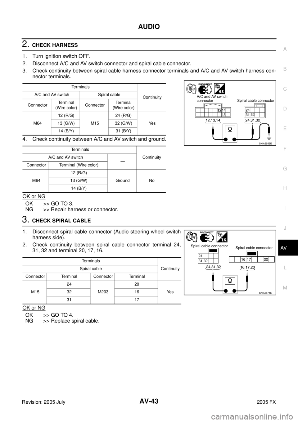
2. CHECK HARNESS
1. Turn ignition switch OFF.
2. Disconnect A/C and AV switch connector and spiral cable connector.
3. Check continuity between spiral cable harness connector terminals and A/C and AV switch harness con- nector terminals.
4. Check continuity between A/C and AV switch and ground.
OK or NG
OK >> GO TO 3.
NG >> Repair harness or connector.
3. CHECK SPIRAL CABLE
1. Disconnect spiral cable connector (Audio steering wheel switch harness side).
2. Check continuity between spiral cable connector terminal 24, 31, 32 and terminal 20, 17, 16.
OK or NG
OK >> GO TO 4.
NG >> Replace spiral cable.
Te r m i n a l s
Continuity
A/C and AV switch Spiral cable
Connector Terminal
(Wire color) Connector Terminal
(Wire color)
M64 12 (R/G)
M15 24 (R/G)
Ye s
13 (G/W) 32 (G/W)
14 (B/Y) 31 (B/Y)
Terminals Continuity
A/C and AV switch
—
Connector Terminal (Wire color)
M64 12 (R/G)
Ground No
13 (G/W)
14 (B/Y)
SKIA5955E
Terminals Continuity
Spiral cable
Connector Terminal Connector Terminal
M15 24
M203 20
Ye s
32 16
31 17
SKIA5874E
Page 644 of 4731

AUDIO AV-45
C
D E
F
G H
I
J
L
M A
B
AV
Revision: 2005 July 2005 FX
2. CHECK AMP. ON SIGNAL
1. Connect audio unit connector.
2. Turn the ignition switch ACC.
3. Check voltage between audio unit harness connector M59 ter- minal 12 (G/W) and ground.
OK or NG
OK >> INSPECTION END (System is OK.)
NG >> Replace audio unit.
Vehicle Speed Signal InspectionAKS007VI
1. CHECK VEHICLE SPEED OPERATION
Start engine and drive vehicle.
Dose speedometer is operated normally?
Ye s > > G O T O 2 .
No >> Check combination meter trouble diagnosis. Refer to DI-15, "
Trouble Diagnosis" .
2. CHECK HARNESS
1. Turn the ignition switch OFF.
2. Disconnect audio unit connector and unified meter and A/C amp. connector.
3. Check continuity between audio unit harness connector M60 ter- minal 22 (W/L) and unified meter and A/C amp. harness connec-
tor M56 terminal 34 (W/L).
4. Check continuity between audio unit harness connector M60 ter- minal 22 (W/L) and ground.
OK or NG
OK >> GO TO 3.
NG >> Repair harness or connector. 12 (G/W) – Ground : Approx. 12 V
SKIA6818E
22 (W/L) – 34(W/L) : Continuity should exist.
22 (W/L) – Ground : Continuity should not exist.
SKIA6807E
Page 645 of 4731

AV-46
AUDIO
Revision: 2005 July 2005 FX
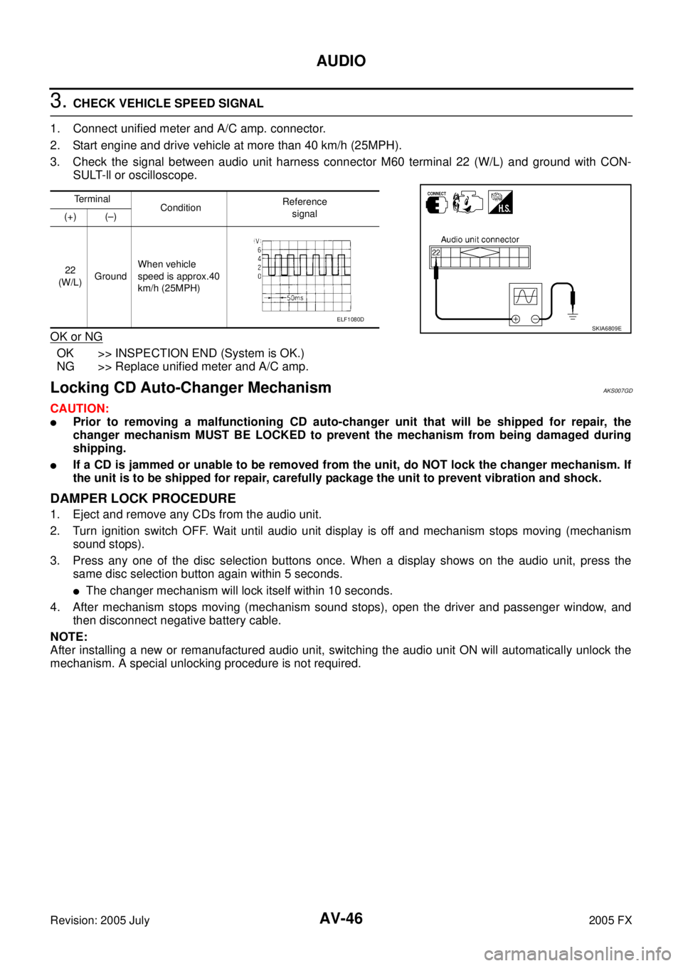
3. CHECK VEHICLE SPEED SIGNAL
1. Connect unified meter and A/C amp. connector.
2. Start engine and drive vehicle at more than 40 km/h (25MPH).
3. Check the signal between audio unit harness connector M60 terminal 22 (W/L) and ground with CON- SULT-ll or oscilloscope.
OK or NG
OK >> INSPECTION END (System is OK.)
NG >> Replace unified meter and A/C amp.
Locking CD Auto-Changer MechanismAKS007GD
CAUTION:
�Prior to removing a malfunctioning CD auto-changer unit that will be shipped for repair, the
changer mechanism MUST BE LOCKED to prevent the mechanism from being damaged during
shipping.
�If a CD is jammed or unable to be removed from the unit, do NOT lock the changer mechanism. If
the unit is to be shipped for repair, carefully package the unit to prevent vibration and shock.
DAMPER LOCK PROCEDURE
1. Eject and remove any CDs from the audio unit.
2. Turn ignition switch OFF. Wait until audio unit display is off and mechanism stops moving (mechanism sound stops).
3. Press any one of the disc selection buttons once. When a display shows on the audio unit, press the same disc selection button again within 5 seconds.
�The changer mechanism will lock itself within 10 seconds.
4. After mechanism stops moving (mechanism sound stops), open the driver and passenger window, and then disconnect negative battery cable.
NOTE:
After installing a new or remanufactured audio unit, switching the audio unit ON will automatically unlock the
mechanism. A special unlocking procedure is not required.
Terminal Condition Reference
signal
(+) (–)
22
(W/L) Ground When vehicle
speed is approx.40
km/h (25MPH)
SKIA6809EELF1080D
Page 650 of 4731
AUDIO ANTENNA AV-51
C
D E
F
G H
I
J
L
M A
B
AV
Revision: 2005 July 2005 FX
AUDIO ANTENNAPFP:28200
System DescriptionAKS007WE
With the ignition switch in ACC or ON, power is supplied
�through 10A fuse [No. 6, located in the fuse block (J/B)]
�to audio unit terminal 10.
Ground is supplied through the case of the antenna amp.
When the radio switch is turned ON, antenna signal is supplied
�through audio unit terminal 5
�to the antenna amp.
Then the antenna amp. is activated.
The amplified radio signals are supplied to the audio unit through the antenna amp.
Page 652 of 4731

AUDIO ANTENNA AV-53
C
D E
F
G H
I
J
L
M A
B
AV
Revision: 2005 July 2005 FX
Terminals and Reference Value for Audio UnitAKS007WW
Antenna Amp. InspectionAKS007WX
1. CHECK ANTENNA FEEDER
Check with visual observation if antenna feeder between audio unit and antenna amp. has disconnection or
malfunction on the mounting part (engagement, looseness of shield earth, etc.).
OK or NG
OK >> GO TO 2
NG >> Replace antenna feeder.
2. CHECK ANTENNA SIGNAL
1. Turn the ignition switch ACC.
2. Check voltage between audio unit harness connector M58 ter- minal 5 (R/W) and ground.
OK or NG
OK >> INSPECTION END (System is OK.)
NG >> Replace audio unit.
Terminal
(Wire color) Item Signal
input/
output Condition
Reference value Example of
symptom
+– Ignition
switch Operation
5 (R/W) Ground Antenna signal Input ACC — Approx. 12 V Receiving status of radio
broadcast becomes bad.
10 (LG/R) Ground ACC power
supply Input ACC — Battery voltage
System does not work
properly.
5 (R/W) – Ground : Approx. 12 V
SKIA6854E
Page 656 of 4731

INTEGRATED DISPLAY SYSTEM AV-57
C
D E
F
G H
I
J
L
M A
B
AV
Revision: 2005 July 2005 FX
INTEGRATED DISPLAY SYSTEMPFP:28090
System DescriptionAKS005U0
A/C AND AV SWITCH SYSTEM
Refer to Owner′s Manual for A/C and AV switch operating instructions.
Using the A/C and AV switch at the center of the instrument panel, the controls of the following systems are
centralized:
�Integrated display system (Drive computer, setting screen, etc.)
�Auto A/C system
�Audio system
PRECAUTION OF LCD MONITOR
�In order to use LED for backlight of a display, by interior temperature, brightness may change. In low tem-
perature, the refreshing rate of the picture also becomes low because of the low response of the LCD
monitor. When the interior becomes warm, however, the LCD recovers the normal display.
�Backlight sometimes flickers or darkens according to the wearing out of LCD and the number of times
switched ON and OFF. In this case, display unit should be replaced. (Exchange only of backlight is impos-
sible.)
POWER SUPPLY AND GROUND
Power is supplied at all times
�through 15A fuse (No. 32, located in fuse and fusible link box)
�to audio unit terminal 6
�to display unit terminal 1 and
�to A/C and AV switch terminal 1.
When ignition switch is in ACC or ON position, power is supplied
�through 10A fuse [No. 6, located in fuse block (J/B)]
�to unified meter and A/C amp. terminal 35
�to audio unit terminal 10
�to display unit terminal 2 and
�to A/C and AV switch terminal 2.
When ignition switch is in ON or START position, power is supplied
�through 10A fuse [No. 12, located in fuse block (J/B)]
�to unified meter and A/C amp. terminal 22 and
�to display unit terminal 3.
Ground is supplied
�to unified meter and A/C amp. terminals 29, 30
�to display unit terminals 6 and 15 and
�to A/C and AV switch terminal 5
�through body grounds M35, M45 and M85.
Ground is supplied through the case of the audio unit.
Page 671 of 4731

AV-72
INTEGRATED DISPLAY SYSTEM
Revision: 2005 July 2005 FX
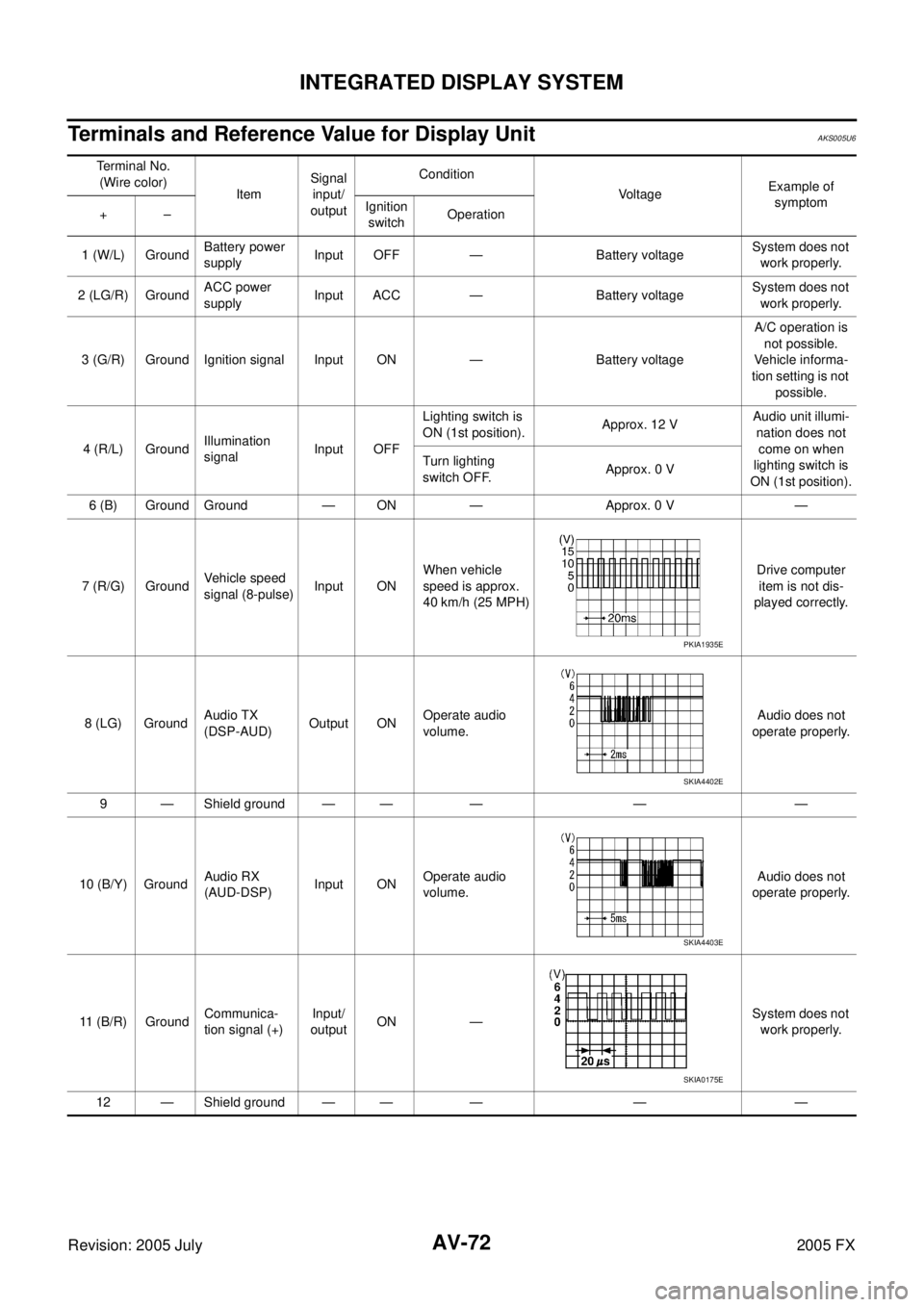
Terminals and Reference Value for Display UnitAKS005U6
Terminal No.
(Wire color) Item Signal
input/
output Condition
Voltage Example of
symptom
+– Ignition
switch Operation
1 (W/L) Ground Battery power
supply Input OFF — Battery voltage System does not
work properly.
2 (LG/R) Ground ACC power
supply Input ACC — Battery voltage System does not
work properly.
3 (G/R) Ground Ignition signal Input ON — Battery voltage A/C operation is
not possible.
Vehicle informa-
tion setting is not possible.
4 (R/L) Ground Illumination
signal Input OFF Lighting switch is
ON (1st position). Approx. 12 V Audio unit illumi-
nation does not
come on when
lighting switch is
ON (1st position).
Turn lighting
switch OFF. Approx. 0 V
6 (B) Ground Ground — ON — Approx. 0 V —
7 (R/G) Ground Vehicle speed
signal (8-pulse) Input ON When vehicle
speed is approx.
40 km/h (25 MPH) Drive computer
item is not dis-
played correctly.
8 (LG) Ground Audio TX
(DSP-AUD) Output ON
Operate audio
volume. Audio does not
operate properly.
9 — Shield ground — — — — —
10 (B/Y) Ground Audio RX
(AUD-DSP) Input ON
Operate audio
volume. Audio does not
operate properly.
11 (B/R) Ground Communica-
tion signal (+) Input/
output ON — System does not
work properly.
12 — Shield ground — — — — —
PKIA1935E
SKIA4402E
SKIA4403E
SKIA0175E
Page 672 of 4731

INTEGRATED DISPLAY SYSTEM AV-73
C
D E
F
G H
I
J
L
M A
B
AV
Revision: 2005 July 2005 FX
Terminals and Reference Value for A/C and AV SwitchAKS005U7
13 (W/R) Ground Communica-
tion signal (-) Input/
output ON — System does not
work properly.
14 (L) — CAN-H — — — — —
15 (B) — Shield ground — — — — —
16 (R) — CAN-L — — — — — Terminal No.
(Wire color) Item Signal
input/
output Condition
Voltag e Example of
symptom
+– Ignition
switch Operation
SKIA0176E
Terminal No.
(Wire color) Item Signal
input/
output Condition
Vo l ta g e Example of
symptom
+– Ignition
switch Operation
1 (W/L) Ground Battery power
supply Input OFF — Battery voltage System does not
work properly.
2 (LG/R) Ground ACC power
supply Input ACC — Battery voltage System does not
work properly.
5 (B) Ground Ground — ON — Approx. 0 V —
6 (B/R) Ground Communica-
tion signal (+) Input/
output ON —
System does not
work properly.
7 — Shield ground — — — — —
8 (W/R) Ground Communica-
tion signal (-) Input/
output ON —
System does not
work properly.
12 (R/G) Ground Steering SW
A Input ON Press MODE
switch. Approx. 0 V
Audio steering
wheel switches
do not function.
Press SEEK UP
switch. Approx. 1.7 V
Press VOL UP
switch. Approx. 3.3 V
Except for above Approx. 5 V
SKIA0175E
SKIA0176E