Page 3458 of 4731
CAN COMMUNICATION LAN-39
[CAN]
C
D E
F
G H
I
J
L
M A
B
LAN
Revision: 2005 July 2005 FX
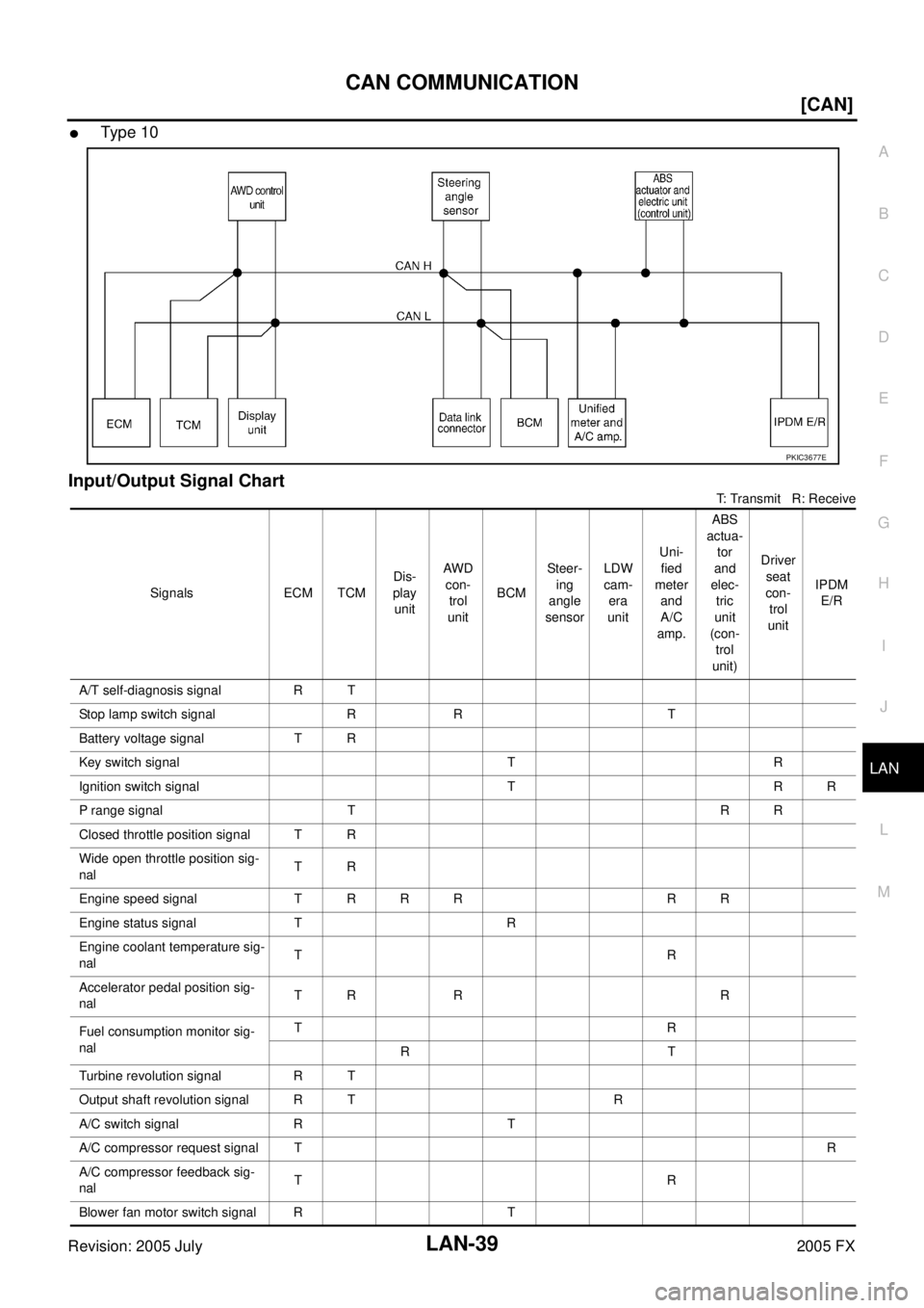
�Type 10
Input/Output Signal Chart
T: Transmit R: Receive
PKIC3677E
Signals ECM TCM Dis-
play unit AWD
con- trol
unit BCM Steer-
ing
angle
sensor LDW
cam- era
unit Uni-
fied
meter and
A/C
amp. ABS
actua- tor
and
elec- tric
unit
(con- trol
unit) Driver
seat
con- trol
unit IPDM
E/R
A/T self-diagnosis signal R T
Stop lamp switch signal R R T
Battery voltage signal T R
Key switch signal T R
Ignition switch signal T R R
P range signal T R R
Closed throttle position signal T R
Wide open throttle position sig-
nal TR
Engine speed signal T R R R R R
Engine status signal T R
Engine coolant temperature sig-
nal TR
Accelerator pedal position sig-
nal TR R R
Fuel consumption monitor sig-
nal TR
RT
Turbine revolution signal R T
Output shaft revolution signal R T R
A/C switch signal R T
A/C compressor request signal T R
A/C compressor feedback sig-
nal TR
Blower fan motor switch signal R T
Page 3462 of 4731
![INFINITI FX35 2005 Service Manual CAN COMMUNICATION LAN-43
[CAN]
C
D E
F
G H
I
J
L
M A
B
LAN
Revision: 2005 July 2005 FX
Battery voltage sig-
nal TR
Key switch signal T R
Ignition switch signal T R R
P range signal T](/manual-img/42/57020/w960_57020-3461.png "INFINITI FX35 2005 Service Manual CAN COMMUNICATION LAN-43
[CAN]
C
D E
F
G H
I
J
L
M A
B
LAN
Revision: 2005 July 2005 FX
Battery voltage sig-
nal TR
Key switch signal T R
Ignition switch signal T R R
P range signal T")
CAN COMMUNICATION LAN-43
[CAN]
C
D E
F
G H
I
J
L
M A
B
LAN
Revision: 2005 July 2005 FX
Battery voltage sig-
nal TR
Key switch signal T R
Ignition switch signal T R R
P range signal T R R R
Closed throttle posi-
tion signal TR R
Wide open throttle
position signal TR
Engine speed signal T R R R R R R
Engine status signal T R
Engine coolant tem-
perature signal TR
Accelerator pedal
position signal TR R R R
Fuel consumption
monitor signal TR
RT
Turbine revolution
signal RT R
Output shaft revolu-
tion signal RT R R
A/C switch signal R T
A/C compressor
request signal T
R
A/C compressor
feedback signal TR
Blower fan motor
switch signal RT
A/C switch/indicator
signal TR
RT
Cooling fan speed
request signal T
R
Position light request
signal RTR R
Low beam request
signal TR
Low beam status sig-
nal R
T
High beam request
signal TR R
High beam status
signal R
T
Front fog light
request signal TR
Signals ECM TCM
Dis-
play
con-
trol
unit AWD
con- trol
unit ICC
unit Intel-
ligent Key unit BCM Steer-
ing
angle
sen- sor LDW
cam- era
unit Uni-
fied
meter and
A/C
amp. ICC
sen-
sor ABS
actu- ator and
elec- tric
unit
(con- trol
unit) Driver
seat
con-
trol
unit IPDM
E/R
Page 3465 of 4731
LAN-46
[CAN]
CAN COMMUNICATION
Revision: 2005 July 2005 FX
*: VK45DE engine model only A/T shift schedule
change demand sig-
nal R
T
Manual mode signal R T
Not manual mode
signal RT
Manual mode shift up
signal RT
Manual mode shift
down signal RT
Manual mode indica-
tor signal TR
Ignition knob switch
signal TR
Snow mode switch
signal RT
TR
Current gear posi-
tion signal* RT
Next gear position
signal* RT
Shift change signal* R T
Shift pattern signal* R T
VDC OFF switch sig-
nal RT
Signals ECM TCM
Dis-
play
con-
trol
unit AW D
con- trol
unit ICC
unit Intel-
ligent Key unit BCM Steer-
ing
angle
sen- sor LDW
cam- era
unit Uni-
fied
meter and
A/C
amp. ICC
sen-
sor ABS
actu- ator and
elec- tric
unit
(con- trol
unit) Driver
seat
con-
trol
unit IPDM
E/R
Page 3488 of 4731
CAN SYSTEM (TYPE 1) LAN-69
[CAN]
C
D E
F
G H
I
J
L
M A
B
LAN
Revision: 2005 July 2005 FX
Case 16
Check IPDM E/R ignition relay circuit continuously sticks “OFF”. Refer to LAN-84, "IPDM E/R Ignition Relay
Circuit Inspection" .
PKIB4456E
Page 3489 of 4731
LAN-70
[CAN]
CAN SYSTEM (TYPE 1)
Revision: 2005 July 2005 FX
Case 17
Check IPDM E/R ignition relay circuit continuously sticks “ON”. Refer to LAN-84, "IPDM E/R Ignition Relay Cir-
cuit Inspection" .
Inspection Between TCM and Data Link Connector CircuitAKS00CFO
1. CHECK HARNESS FOR OPEN CIRCUIT
1. Turn ignition switch OFF.
2. Disconnect the battery cable from the negative terminal.
3. Disconnect ECM connector and harness connector M82.
4. Check continuity between harness connector M82 terminals 14H (L), 15H (R) and data link connector M5 terminals 6 (L), 14
(R).
OK or NG
OK >> Connect all the connectors and diagnose again. Refer to LAN-7, "
TROUBLE DIAGNOSES WORK FLOW" .
NG >> Repair harness.
PKIB4457E
14H (L) - 6 (L) : Continuity should exist.
15H (R) - 14 (R) : Continuity should exist.
SKIA6861E
Page 3490 of 4731
![INFINITI FX35 2005 Service Manual CAN SYSTEM (TYPE 1) LAN-71
[CAN]
C
D E
F
G H
I
J
L
M A
B
LAN
Revision: 2005 July 2005 FX
Inspection Between Data Link Connector and Unified Meter and A/C Amp. Cir-
cuit
AKS00CFP
1. CHECK](/manual-img/42/57020/w960_57020-3489.png "INFINITI FX35 2005 Service Manual CAN SYSTEM (TYPE 1) LAN-71
[CAN]
C
D E
F
G H
I
J
L
M A
B
LAN
Revision: 2005 July 2005 FX
Inspection Between Data Link Connector and Unified Meter and A/C Amp. Cir-
cuit
AKS00CFP
1. CHECK")
CAN SYSTEM (TYPE 1) LAN-71
[CAN]
C
D E
F
G H
I
J
L
M A
B
LAN
Revision: 2005 July 2005 FX
Inspection Between Data Link Connector and Unified Meter and A/C Amp. Cir-
cuit
AKS00CFP
1. CHECK HARNESS FOR OPEN CIRCUIT
1. Turn ignition switch OFF.
2. Disconnect the battery cable from the negative terminal.
3. Disconnect ECM connector and unified meter and A/C amp. connector.
4. Check continuity between data link connector M5 terminals 6 (L), 14 (R) and unified meter and A/C amp. harness connector
M55 terminals 1 (L), 11 (R).
OK or NG
OK >> Connect all the connectors and diagnose again. Refer to LAN-7, "
TROUBLE DIAGNOSES WORK FLOW" .
NG >> Repair harness.
Inspection Between Unified Meter and A/C Amp. and ABS Actuator and Electric
Unit (Control Unit) Circuit
AKS00CFQ
1. CHECK CONNECTOR
1. Turn ignition switch OFF.
2. Disconnect the battery cable from the negative terminal.
3. Check following terminals and connectors for damage, bend and loose connection (connector side and harness side).
–Harness connector M41
–Harness connector E211
OK or NG
OK >> GO TO 2.
NG >> Repair terminal or connector.
2. CHECK HARNESS FOR OPEN CIRCUIT
1. Disconnect unified meter and A/C amp. connector and harness connector M41.
2. Check continuity between unified meter and A/C amp. harness connector M55 terminals 1 (L), 11 (R) and harness connector
M41 terminals 15G (L), 14G (R).
OK or NG
OK >> GO TO 3.
NG >> Repair harness. 6 (L) - 1 (L) : Continuity should exist.
14 (R) - 11 (R) : Continuity should exist.
SKIA6862E
1 (L) - 15G (L) : Continuity should exist.
11 (R) - 14G (R) : Continuity should exist.
SKIA6863E
Page 3491 of 4731
![INFINITI FX35 2005 Service Manual LAN-72
[CAN]
CAN SYSTEM (TYPE 1)
Revision: 2005 July 2005 FX
3. CHECK HARNESS FOR OPEN CIRCUIT
1. Disconnect ABS actuator and electric unit (control unit) connector.
2. Check continuity between harn](/manual-img/42/57020/w960_57020-3490.png "INFINITI FX35 2005 Service Manual LAN-72
[CAN]
CAN SYSTEM (TYPE 1)
Revision: 2005 July 2005 FX
3. CHECK HARNESS FOR OPEN CIRCUIT
1. Disconnect ABS actuator and electric unit (control unit) connector.
2. Check continuity between harn")
LAN-72
[CAN]
CAN SYSTEM (TYPE 1)
Revision: 2005 July 2005 FX
3. CHECK HARNESS FOR OPEN CIRCUIT
1. Disconnect ABS actuator and electric unit (control unit) connector.
2. Check continuity between harness connector E211 terminals 15G (L), 14G (R) and ABS actuator and electric unit (control
unit) harness connector E56 terminals 11 (L), 15 (R).
OK or NG
OK >> Connect all the connectors and diagnose again. Refer to LAN-7, "
TROUBLE DIAGNOSES WORK FLOW" .
NG >> Repair harness.
Inspection Between ABS Actuator and Electric Unit (Control Unit) and Driver
Seat Control Unit Circuit
AKS00CFR
1. CHECK CONNECTOR
1. Turn ignition switch OFF.
2. Disconnect the battery cable from the negative terminal.
3. Check following terminals and connectors for damage, bend and loose connection (connector side and harness side).
–Harness connector E205
–Harness connector B5
OK or NG
OK >> GO TO 2.
NG >> Repair terminal or connector.
2. CHECK HARNESS FOR OPEN CIRCUIT
1. Disconnect ABS actuator and electric unit (control unit) connector and harness connector E205.
2. Check continuity between ABS actuator and electric unit (control unit) harness connector E56 terminals 11 (L), 15 (R) and har-
ness connector E205 terminals 3 (L), 10 (R).
OK or NG
OK >> GO TO 3.
NG >> Repair harness. 15G (L) - 11 (L) : Continuity should exist.
14G (R) - 15 (R) : Continuity should exist.
SKIA6864E
11 (L) - 3 (L) : Continuity should exist.
15 (R) - 10 (R) : Continuity should exist.
SKIA6880E
Page 3492 of 4731
![INFINITI FX35 2005 Service Manual CAN SYSTEM (TYPE 1) LAN-73
[CAN]
C
D E
F
G H
I
J
L
M A
B
LAN
Revision: 2005 July 2005 FX
3. CHECK HARNESS FOR OPEN CIRCUIT
1. Disconnect harness connector B8.
2. Check continuity betwee](/manual-img/42/57020/w960_57020-3491.png "INFINITI FX35 2005 Service Manual CAN SYSTEM (TYPE 1) LAN-73
[CAN]
C
D E
F
G H
I
J
L
M A
B
LAN
Revision: 2005 July 2005 FX
3. CHECK HARNESS FOR OPEN CIRCUIT
1. Disconnect harness connector B8.
2. Check continuity betwee")
CAN SYSTEM (TYPE 1) LAN-73
[CAN]
C
D E
F
G H
I
J
L
M A
B
LAN
Revision: 2005 July 2005 FX
3. CHECK HARNESS FOR OPEN CIRCUIT
1. Disconnect harness connector B8.
2. Check continuity between harness connector B5 terminals 3 (L), 10 (R) and harness connector B8 terminals 14 (L), 15 (R).
OK or NG
OK >> Connect all the connectors and diagnose again. Refer to LAN-7, "
TROUBLE DIAGNOSES WORK FLOW" .
NG >> Repair harness.
ECM Circuit InspectionAKS00CFS
1. CHECK CONNECTOR
1. Turn ignition switch OFF.
2. Disconnect the battery cable from the negative terminal.
3. Check terminals and connector of ECM for damage, bend and loose connection (control module side and harness side).
OK or NG
OK >> GO TO 2.
NG >> Repair terminal or connector.
2. CHECK HARNESS FOR OPEN CIRCUIT
1. Disconnect ECM connector.
2. Check resistance between ECM harness connector M90 termi- nals 94 (L) and 86 (R).
OK or NG
OK >> Replace ECM.
NG >> Repair harness between ECM and harness connector M82.
TCM Circuit InspectionAKS00CFT
1. CHECK CONNECTOR
1. Turn ignition switch OFF.
2. Disconnect the battery cable from the negative terminal.
3. Check following terminals and connectors for damage, bend and loose connection (control module side and harness side).
–A/T assembly connector
–Harness connector F102
–Harness connector M82
OK or NG
OK >> GO TO 2.
NG >> Repair terminal or connector. 3 (L) - 14 (L) : Continuity should exist.
10 (R) - 15 (R) : Continuity should exist.
SKIA6881E
94 (L) - 86 (R) : Approx. 108 - 132 Ω
PKIA9860E
![INFINITI FX35 2005 Service Manual LAN-46
[CAN]
CAN COMMUNICATION
Revision: 2005 July 2005 FX
*: VK45DE engine model only A/T shift schedule
change demand sig-
nal R
T
Manual mode signal R T
Not manual mode
signal RT
Manual](/manual-img/42/57020/w960_57020-3464.png "INFINITI FX35 2005 Service Manual LAN-46
[CAN]
CAN COMMUNICATION
Revision: 2005 July 2005 FX
*: VK45DE engine model only A/T shift schedule
change demand sig-
nal R
T
Manual mode signal R T
Not manual mode
signal RT
Manual")
![INFINITI FX35 2005 Service Manual CAN SYSTEM (TYPE 1) LAN-69
[CAN]
C
D E
F
G H
I
J
L
M A
B
LAN
Revision: 2005 July 2005 FX
Case 16
Check IPDM E/R ignition relay circuit continuously sticks “OFF”. Refer to LAN-84, "IPD](/manual-img/42/57020/w960_57020-3487.png "INFINITI FX35 2005 Service Manual CAN SYSTEM (TYPE 1) LAN-69
[CAN]
C
D E
F
G H
I
J
L
M A
B
LAN
Revision: 2005 July 2005 FX
Case 16
Check IPDM E/R ignition relay circuit continuously sticks “OFF”. Refer to LAN-84, \"IPD")
![INFINITI FX35 2005 Service Manual LAN-70
[CAN]
CAN SYSTEM (TYPE 1)
Revision: 2005 July 2005 FX
Case 17
Check IPDM E/R ignition relay circuit continuously sticks “ON”. Refer to LAN-84, "IPDM E/R Ignition Relay Cir-
cuit Inspection"](/manual-img/42/57020/w960_57020-3488.png "INFINITI FX35 2005 Service Manual LAN-70
[CAN]
CAN SYSTEM (TYPE 1)
Revision: 2005 July 2005 FX
Case 17
Check IPDM E/R ignition relay circuit continuously sticks “ON”. Refer to LAN-84, \"IPDM E/R Ignition Relay Cir-
cuit Inspection\"")