Page 129 of 205

44IN CASE OF EMERGENCY
28
If you suspect a blown fuse, follow this procedure:
1. Turn off the ignition and all other
switches.
2. Open the fuse box and examine each fuse. Remove each fuse by pulling it toward you (a small "fusepuller" tool is contained in the fuse box to simplify this operation).
3. Be sure to check all other fuses even if you find one that appears tohave burned out.
HSR40224. Replace the blown fuse by pressing
a new fuse of the same rating into place. The fuse should be a snug fit. If it is not, have the fuse clip repaired or replaced by a Hyundai dealer. Ifyou do not have a spare fuse, you may be able to borrow a fuse of the same or lower rating from an acces-sory you can temporarily get along without (the radio or cigarette light- er, for example). Always rememberto replace the borrowed fuse.
G200B02A
Good
Burned out
!
CAUTION:
A burned-out fuse indicates that there is a problem in the electrical circuit. If you replace a fuse and it blows as soon as the accessory isturned on, the problem is serious and should be referred to a Hyun- dai dealer for diagnosis and repair.Never replace a fuse with anything except a fuse with the same or a lower amperage rating. A highercapacity fuse could cause damage and create a fire hazard. NOTE: See page 4-40 for the fuse panel descriptions.
Page 130 of 205

4
CORROSION PREVENTION AND APPEARANCE CARE
29
4
IN CASE OF EMERGENCY
29
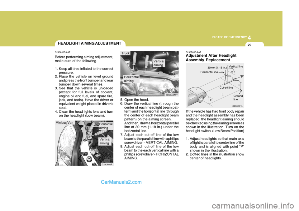
G290B03P-AAT Adjustment After Headlight Assembly Replacement If the vehicle has had front body repair and the headlight assembly has been replaced, the headlight aiming should be checked using the aiming screen asshown in the illustration. Turn on the headlight switch. (Low Beam Position)
1. Adjust headlights so that main axis
of light is parallel to center line of the body and is aligned with point "P"shown in the illustration.
2. Dotted lines in the illustration show
center of headlights.
5. Open the hood.
6. Draw the vertical line (through the
center of each headlight beam pat- tern) and the horizontal line (through the center of each headlight beam pattern) on the aiming screen.And then, draw a horizontal parallel line at 30 mm (1.18 in.) under the horizontal line.
7. Adjust each cut-off line of the low beam to the parallel line with a phillipsscrewdriver - VERTICAL AIMING.
8. Adjust each cut-off line of the low beam to the each vertical line with aphillips screwdriver - HORIZONTALAIMING.
Horizontal aiming
Verticalaiming
G290A01P-1
Truck
G290B01L
LW
H
H Cut-off line
Ground line
"P"
Horizontal line
30mm (1.18 in.) Vertical line
HEADLIGHT AIMING ADJUSTMENT
G290A03P-AAT Before performing aiming adjustment, make sure of the following.
1. Keep all tires inflated to the correct pressure.
2. Place the vehicle on level ground
and press the front bumper and rear bumper down several times.
3. See that the vehicle is unloaded
(except for full levels of coolant,engine oil and fuel, and spare tire, jack, and tools). Have the driver or equivalent weight placed in driver'sseat.
4. Clean the head lights lens and turn
on the headlight (Low beam).
Minibus/Van
G290A02P
Horizontal aiming
Verticalaiming
Page 131 of 205
44IN CASE OF EMERGENCY
30
Specifications: "H": Horizontal center line of headlights from ground "W":Distance between each headlight cen-ter "L": Distance between the headlights and the wall that the lights are tested against : 3,000 mm (118.11 in.).
2WD 4WD
Long wheel base
Extra long
wheel base
MINIBUS 894
(35.20) 1006
(39.61)
- - VAN
855
(33.66)
--- TRUCK
--
847
(33.35) 845
(33.27)2WD 4WD
Long wheel base
Extra long
wheel base
MINIBUS
- - VAN
-- TRUCK
--
1272
(50.08)
1380
(54.33)
REPLACEMENT OF LIGHT BULBS
G260A02A-AAT Before attempting to replace a head- light bulb, be sure the switch is turned to the "OFF" position. The next paragraph shows how toreach the headlight bulbs so they may be changed. Be sure to replace the burned-out bulb with one of the samenumber and wattage rating. See page 4-35 for the wattage descrip- tions.
CAUTION:
Keep the lamps out of contact withpetroleum products, such as oil,gasoline, etc.
!
mm(in.)
mm(in.)
Page 132 of 205
4
CORROSION PREVENTION AND APPEARANCE CARE
31
4
IN CASE OF EMERGENCY
31
HSRFL274
7. Push the bulb spring to remove the headlight bulb. HSRFL273
6. Turn the plastic cover counterclock- wise and remove it.
4. Using a spanner of the correct size,
remove the headlight assembly mounting bolts.
HSRFL272
5. Disconnect the power cord from the back of the headlight.
Replacement instructions:
1. Allow the bulb to cool. Wear eye
protection.
2. Open the engine hood.
3. Always grasp the bulb by its plastic base, avoid touching the glass. HSRFL270
G270A01P-GAT HEADLIGHT AND FRONT TURN SIGNAL LIGHT (Minibus/van)
Turn signal light
HSRFL271
Front position light
Headlight
Page 133 of 205

44IN CASE OF EMERGENCY
32
8. Remove the protective cap from the
replacement bulb and install the new bulb by matching the plastic base with the headlight hole. Retighten the bulb spring and reconnect thepower cord.
9. Use the protective cap and carton to
promptly dispose of the old bulb.
10.Check for proper headlight aim.
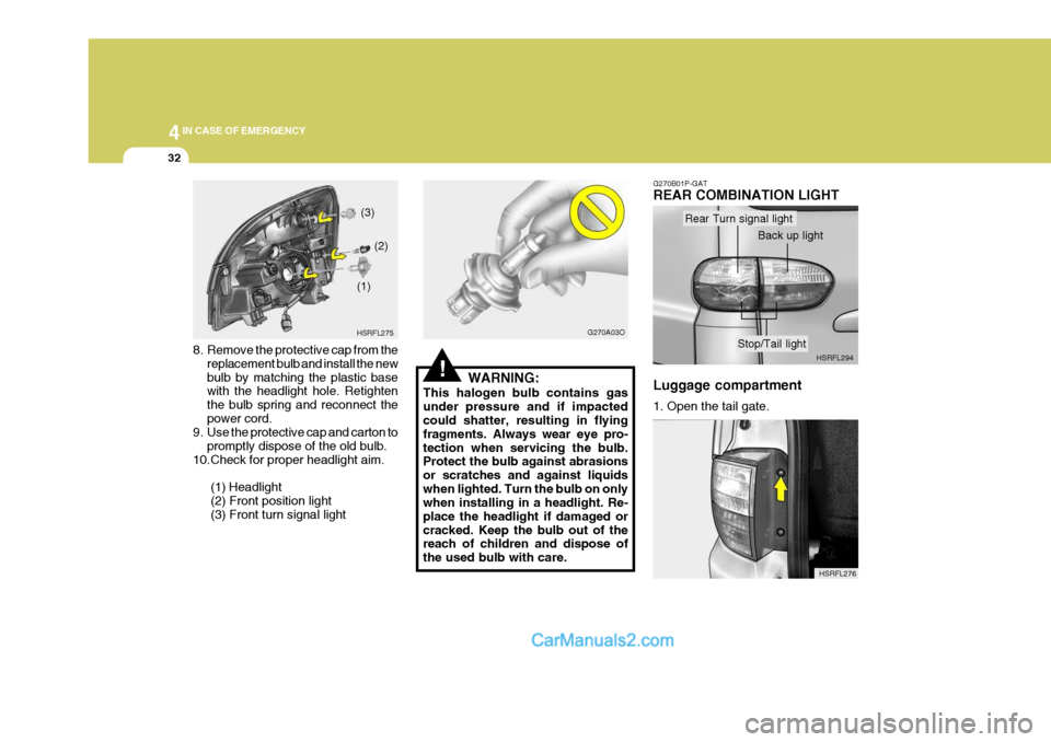
(1) Headlight(2) Front position light (3) Front turn signal light HSRFL275
(1)
(2)
(3)
!
G270A03O
WARNING:
This halogen bulb contains gas under pressure and if impacted could shatter, resulting in flying fragments. Always wear eye pro-tection when servicing the bulb. Protect the bulb against abrasions or scratches and against liquidswhen lighted. Turn the bulb on only when installing in a headlight. Re- place the headlight if damaged orcracked. Keep the bulb out of the reach of children and dispose of the used bulb with care.
HSRFL276
G270B01P-GAT REAR COMBINATION LIGHT Luggage compartment 1. Open the tail gate.
HSRFL294
Rear Turn signal light
Back up light
Stop/Tail light
Page 134 of 205
4
CORROSION PREVENTION AND APPEARANCE CARE
33
4
IN CASE OF EMERGENCY
33
3. To replace the rear combination light,
remove it from the bulb holder and install the new bulb.
(1) Back up light
(2) Stop/Tail light HSRFL293
(1)
(2)
2. Remove the mounting screws of the
rear combination light with a phillips screwdriver. 4. To replace the rear combination
light, remove it from the bulb holderand install the new bulb.
(1) Rear turn signal light
(2) Stop/Tail light
HSRFL277 Tail gate
1. Open the tail gate.
2. Remove the plastic cover with pull-
ing it. HSRFL279
3. Disconnect the power cord from the
bulb base in the back of the rear comdination light.
HSRFL278(1)
(2)
Page 135 of 205
44IN CASE OF EMERGENCY
34
HSRFL283
G270C01A-GAT SIDE REPEATER (If installed)
1. Push the cover toward the front of
the vehicle and remove it. HSRFL292
3. Replace with a new bulb. HSRFL284
2. Disconnect the power cord. G270D01P-GAT INTERIOR LIGHT Map light 1. Remove the plastic cover with a flat-
head screwdriver. HSRFL300
HSRFL297
With sunroof
Without sunroof
Page 136 of 205
4
CORROSION PREVENTION AND APPEARANCE CARE
35
4
IN CASE OF EMERGENCY
35
Without sunroof
HSRFL2902. Replace with a new bulb. HSRFL301
With sunroof
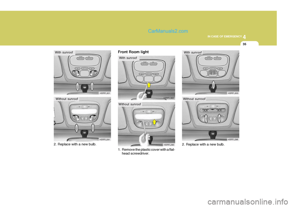
Without sunroof HSRFL291Front Room light
1. Remove the plastic cover with a flat-
head screwdriver. HSRFL298
2. Replace with a new bulb.
HSRFL302
With sunroof
Without sunroof HSRFL303
With sunroof