2005 Hyundai Azera ignition
[x] Cancel search: ignitionPage 258 of 297

6 DO-IT-YOURSELF MAINTENANCE
22
1. Turn off the ignition and all other
switches.
2. Open the fuse box and examine each fuse. Remove each fuse by pulling it toward you (a small "fusepuller" tool is contained in the relay and fuse box of the engine room to simplify this operation).
G200B02NF
3. Be sure to check all other fuses even if you find one that appears tohave burned out.G200B01NF-GAT Replacing Accessory Fuse
G200B01TG
The fuse box for the lights and other electrical accessories will be found in the left side of the crash pad. Insidethe box you will find a list showing the circuits protected by each fuse. If any of your car's lights or other electrical accessories stop working, a blown fuse could be the reason. If the fuse has burned out, you will see thatthe metal strip inside the fuse has burned through. If you suspect a blown fuse, follow this procedure:
CAUTION:
When replacing a fusible link, never
use anything but a new fusible link with the same or lower amper- age rating. Never use a piece ofwire or a higher-rated fusible link. This could result in serious dam- age and create a fire hazard.
!
Page 261 of 297

6
DO-IT-YOURSELF MAINTENANCE
25
!
CHECKING ELECTRIC COOLING FANS
G220A01A-AAT
WARNING:
The cooling fan is controlled by
engine coolant temperature and may sometimes operate even whenthe engine is not running. Use extreme caution when working near the blades of the cooling fan, sothat you are not injured by a rotat- ing fan blade. As the engine cool- ant temperature decreases the fanwill automatically shut off. This is a normal condition.
G220B01NF-GAT
Checking Engine Cooling Fan
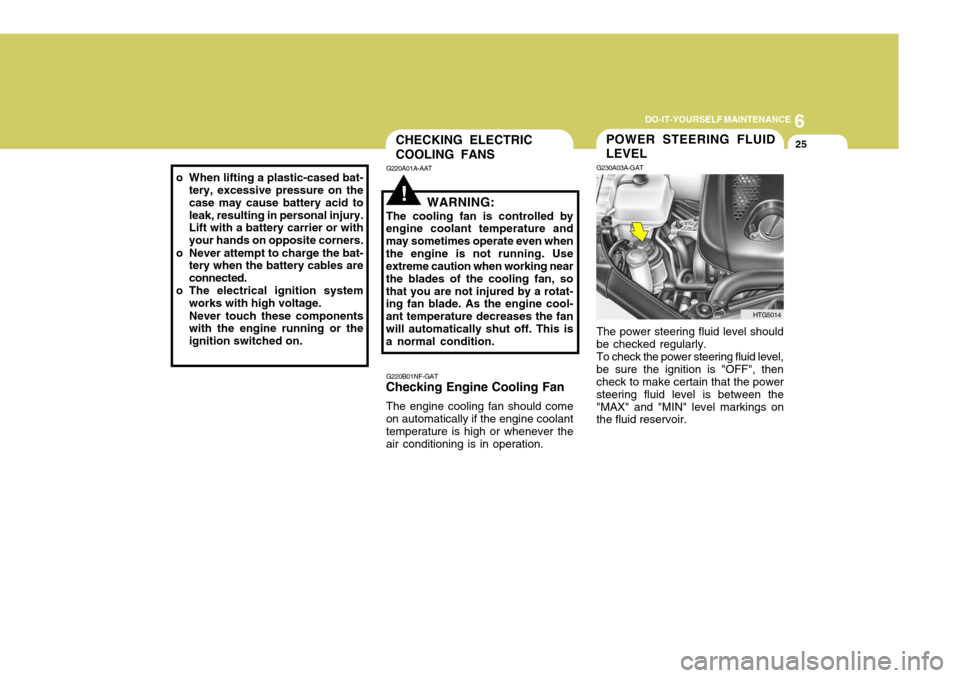
The engine cooling fan should come on automatically if the engine coolant temperature is high or whenever the air conditioning is in operation.POWER STEERING FLUID LEVEL
G230A03A-GAT The power steering fluid level should be checked regularly.To check the power steering fluid level,be sure the ignition is "OFF", then check to make certain that the power steering fluid level is between the"MAX" and "MIN" level markings on the fluid reservoir.
HTG5014
o When lifting a plastic-cased bat-
tery, excessive pressure on the case may cause battery acid toleak, resulting in personal injury. Lift with a battery carrier or with your hands on opposite corners.
o Never attempt to charge the bat- tery when the battery cables areconnected.
o The electrical ignition system works with high voltage. Never touch these components with the engine running or the ignition switched on.
Page 264 of 297

6 DO-IT-YOURSELF MAINTENANCE
28
Replacement instructions:
1. Allow the bulb to cool. Wear eye protection.
2. Open the engine hood and discon- nect the negative (-) post of the battery.
3. Always grasp the bulb by its plastic base, avoid touching the glass.
G270A01TG-GAT
HEADLIGHT AND FRONT FOG LIGHT
Headlight (High beam) Headlight(Low beam)
G270A01TG
Front Fog Light
REPLACEMENT OF LIGHT BULBS
G260A01TG-GAT Before attempting to replace a light
bulb, be sure the ignition switch is turned to the "OFF" position.
The next paragraph shows how to
reach the light bulbs so they may bechanged. Be sure to replace theburned-out bulb with one of the same number and wattage rating.
See page 6-36 for the wattage descrip-
tions.
! CAUTION:
o Keep the lights out of contact with petroleum products, such as oil, gasoline, etc.
o Be sure to replace the LED type
equipped bulbs with an assem- bly.
o If you don't have necessary tools, the correct bulbs and the exper-tise, consult your authorized Hyundai dealer. CAUTION:
o The headlight aiming should be checked by an authorized Hyundaidealer after replacing the head-light bulbs.
o If your vehicle is equipped with
HID (High Intensity Discharge) type headlight, you must not replace or inspect the headlight. It has a danger of an electric shock. If the headlight is not work- ing, have your vehicle inspectedby your Hyundai Dealer.
! Headlight
Page 274 of 297

6 DO-IT-YOURSELF MAINTENANCE
38
1 2 3 4 5 6 7 8 9 10 11 12 13 14 15 16 17 18 19 20 21 22 23 24
HORNTAIL
ECU IG1
DRL
FR FOG
A/CON
F/PUMP
DIODE ATM
STOP
H/LP LO RH
S/ROOF
H/LP WASHER
H/LP HI
ECU (B+)
SNSR3 SNSR1 SNSR2B/UP
IGN COIL
ECU (IG1)
H/LP LO ABS PROTECTED COMPONENTS
ABS/ESP Control module, Multipurpose check connectorABS/ESP Control module, Multipurpose check connector Fuse(FR P/SEAT, T/LID, T/SIG, TILT, PEDAL, RR CURTAIN) Defogger relay Blower relay Fuse(P/WDW LH, P/WDW RH) Start relay, Ignition switch(IG2, START) Engine control unit relay Fuse(KEY SOL, ECS/RR FOG), Power connector Ignition switch(ACC, IG1) Fusible link(ABS1, ABS2, RR HTD, BLOWER) Horn relay Tail light relay PCM (Spare) Burglar alarm horn relay Front fog light relay A/C Relay Fuel pump relay (Spare) ATM Control relay Stop light switch HID Relay Overhead console lamp Headlight washer motor Headlight relay (HIGH) PCM Injector#1~#6, A/C Relay, Cooling fan relay Mass air flow sensor, PCM, Immobilizer control module, Oil control valve#1/#2, Variable intake manifold valve Oxygen Sensor#1~#4 Back-up light switch, Stop light switch, Transaxle range switch, Vehicle speed sensor Ignition coil#1~#6, Condenser PCM Headlight relay(LOW) ABS/ESP Control module, Multipurpose check connector
ABS1 ABS2
I/P (B+)1
RR HTD
BLOWER
P/WDW IGN2
ECU RLY I/P (B+)2
IGN1ALT FUSE RATING
40A20A 40A 40A 40A 40A 40A 30A 30A 30A
150A
15A 20A 10A 10A 15A 15A 10A 20A
-
20A 15A 15A 15A 20A 20A 10A 10A 15A 15A 10A 20A 10A 20A 10ADESCRIPTION
FUSIBLE LINK
FUSE
Page 290 of 297

9
VEHICLE SPECIFICATIONS
3
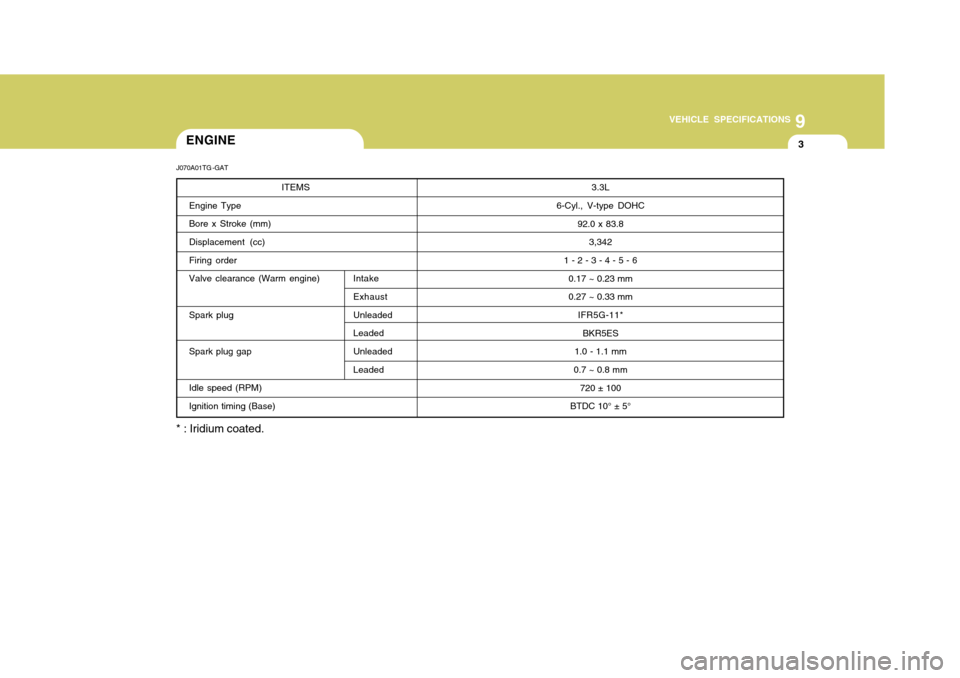
3.3L
6-Cyl., V-type DOHC 92.0 x 83.83,342
1 - 2 - 3 - 4 - 5 - 6 0.17 ~ 0.23 mm 0.27 ~ 0.33 mm
IFR5G-11*BKR5ES
1.0 - 1.1 mm
0.7 ~ 0.8 mm 720 ± 100
BTDC 10° ± 5°ENGINE
J070A01TG -GAT
ITEMS
Engine Type Bore x Stroke (mm) Displacement (cc) Firing orderValve clearance (Warm engine) Intake Exhaust
Spark plug Unleaded Leaded
Spark plug gap Unleaded
Leaded
Idle speed (RPM) Ignition timing (Base)
* : Iridium coated.
Page 295 of 297

10INDEX
4
G General Checks ........................................................... 6-3
Glove Box ................................................................. 1-95
HHazard Warning System ............................................ 1-83
Headlight
Aiming adjustment .................................................. 6-26
Leveling device system .......................................... 1-82
Bulb replacement .................................................... 6-28
Switch ..................................................................... 1-77
Washer switch ........................................................ 1-82
Heating and Cooling Control ....................................1-113
Heating and Ventilation ............................................ 1-114
Air flow control ........................................... 1-115, 1-128
Air intake control switch ............................ 1-117, 1-126
Air quality control system ..................................... 1-126
Bi-level heating ..................................................... 1-118
Defrosting/Defogging .................................. 1-119, 1-130
Fan speed control (Blower control) ............ 1-115, 1-125
Temperature control ................................... 1-115, 1-127
High-Mounted Rear Stop Light .................................1-103
Hood Release .......................................................... 1-105
Horn ......................................................................... 1-107
I Ignition Switch ............................................................. 2-3
Immobilizer System ..................................................... 1-5
Limp home procedures ............................................. 1-8
Key ........................................................................... 1-5 Instrument Cluster and
Indicator Lights ..................... 1-58
Instrument Panel Light Control (Rheostat) .................1-85
Intergrated Memory System (I.M.S) ..........................1-26
Interior Light ............................................................... 1-93
Intermittent Wiper ...................................................... 1-82
J Jump Starting .............................................................. 3-3
K
Key .............................................................................. 1-4 If you lose your keys ............................................. 3-13
Positions ................................................................... 2-4
L Light Bulbs Repl acement ........................................... 6-28
Light Bulbs Watages ................................................. 6-36
Lubrication Chart .......................................................... 9-4
M Maintenance Intervals Explanation of scheduled maintenance items ......... 5-7
Maintenance under severe usage conditions .......... 5-6 Scheduled maintenance ........................................... 5-4
Service requirements ................................................ 5-2
Maintenance Precautions ............................................ 6-4
Mirrors
Day/night inside rearview mirror .............................. 1-99
Outside rearview m irror ........................................... 1-96
Outside rearview mirror heater ................................1-98