Page 368 of 414
.
Do you have f uel? Check the f uel
gauge;")
Are you using a properly coded
key? An improperly coded key will
cause the immobilizer system
indicator in the instrument panel
to blink rapidly (see page ).
Do you have f uel? Check the f uel
gauge; the low f uel indicator may
not be working.
There may be an electrical
problem, such as no power to the
f uel pump. Check all the f uses
(see page ).
If youfindnothingwrong,youwill
need a qualif ied technician to f ind
the problem. See on page . Although this seems like a simple
procedure, you should take several
precautions.
Open the hood, and check the
physical condition of the battery.
In very cold weather, check the
condition of the electrolyte. If it
seems slushy or f rozen, do not try
jump starting until it thaws.
You cannot start your vehicle by
pushing or pulling it. Turn of f all the electrical acces-
sories: heater, A/C, climate
control, audio system, lights, etc.
Put the transmission in Neutral or
Park, and set the parking brake.
1.
2.
376
381 129
CONT INUED
Emergency
Towing Jump Starting
To Jump Start Your Vehicle:
If the Engine Won’t Start, Jump Starting
T aking Care of t he Unexpect ed
367
A battery can explode if you do
not follow the correct procedure,
seriously injuring anyone
nearby.
Keep all sparks, open flames,
and smoking materials away
from the battery.
If a battery sits in extreme cold, the
electrolyte inside can f reeze.
Attempting to jump start with a f rozen
battery can cause it to rupture.
Page 374 of 414

However, if the brake pedal does not
f eel normal, you should take
immediate action. A problem in one
part of the system’s dual circuit
design will still give you braking at
two wheels. You will f eel the brake
pedal go down much f arther bef ore
the vehicle begins to slow down, and
you will have to press harder on the
pedal.
Slow down by shif ting to a lower
gear, and pull to the side of the road
when it is saf e. Because of the long
distance needed to stop, it is
hazardous to drive the vehicle. You
should have it towed and repaired as
soon as possible (seeon page ). If you must drive the vehicle a short
distance in this condition, drive
slowly and caref ully.
If the brake system indicator comes
on while driving, the brake f luid level
is probably low. Press lightly on the
brake pedal to see if it f eels normal.
If it does, check the brake f luid level
thenexttimeyoustopataservice
station (see page ).
If the f luid level is low, take your
vehicle to a dealer, and have the
brake system inspected f or leaks or
worn brake pads. The brake system
indicator normally
comesonwhenyou
turn the ignition switch to ON (II),
and as a reminder to check the
parking brake. It will stay on if you
do not f ully release the parking
brake. If the ABS indicator and the VSA
indicator come on with the brake
system indicator, have the vehicle
inspected by your dealer
immediately.
You will also see a ‘‘CHECK BRAKE
SYSTEM’’ message on the multi-
inf ormation display when this
indicator comes on.
335
381
On Touring model
Emergency
Towing
Brake System Indicator
T aking Care of t he Unexpect ed
373
U.S. Canada
Page 377 of 414

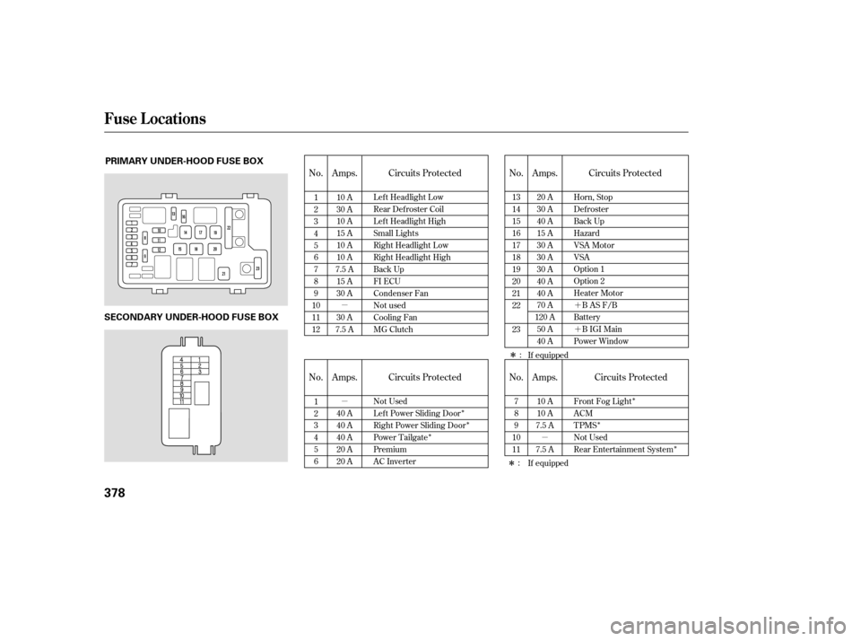
Check the smaller f uses in the
under-hood f use box and all the
fuses in the interior fuse boxes by
pulling out each f use with the f use
puller provided in the primary
under-hood f use box.
Turn the ignition switch to LOCK
(0). Make sure the headlights and
all other accessories are off.
Remove the cover f rom the f use
box. Check each of the large f uses in
the primary under-hood f use box
by looking through the top at the
wire inside. Removing these f uses
requires a Phillips-head
screwdriver.
If something electrical in your
vehicle stops working, the first thing
youshouldcheckforisablownfuse.
Determine f rom the chart on pages
through , or the diagram on
thefuseboxlid,whichfuseorfuses
control that device. The diagram f or
theinteriordriver’ssidefuseboxis
on the kick panel below the f use box.
Check those f uses f irst, but check all
the f uses bef ore deciding that a
blown f use is the cause. Replace any
blown f uses, and check if the device
works.
1.
2. 3.
4.
378 380
Checking and Replacing Fuses
Fuses
376
FUSE
BLOWN FUSE PULLER
Page 379 of 414
�µ
�µ�´
�´
�µ
�Î
�Î
�Î �Î
�Î �Î
�Î �Î
No. Amps. No.
No. Amps. Circuits Protected
Amps. Circuits Protected
No. Amps.
Circuits Protected Circuits Protected
1
2
3
4
5
6
7
8
9
10
11
12 10 A
30 A
10 A
15 A
10 A
10 A
7.5 A 15 A
30 A
30 A
7.5 A
If equipped
13
14
15
16
17
18
19
20
21
22
23
If equipped
1
2
3
4
5
6
40 A
40 A
40 A
20 A
20 A Left Headlight Low
Rear Defroster Coil
Lef t Headlight High
Small Lights
Right Headlight Low
Right Headlight High
Back Up
FI ECU
Condenser Fan
Not used
Cooling Fan
MG Clutch
20 A
30 A
40 A
15 A
30 A
30 A
30 A
40 A
40 A
70 A
120 A 50 A
40 A Horn, Stop
Defroster
Back Up
Hazard
VSA Motor
VSA
Option 1
Option 2
Heater Motor
BASF/B
Battery BIGIMain
Power Window
7
8
9
10
11 10 A
10 A
7.5 A
7.5 A
Not Used
Lef t Power Sliding Door
Right Power Sliding Door
Power Tailgate
Premium
AC Inverter Front Fog Light
ACM
TPMS
Not Used
Rear Entertainment System
:
:
Fuse Locations
378
PRIMARY UNDER-HOOD FUSE BOX
SECONDARY UNDER-HOOD FUSE BOX
Page 380 of 414
�µ
�µ�µ�µ
�Î
�Î�Î
�Î
�Î�Î �Î�Î
�Î�Î �Î�Î
�Î�Î
No. Amps. No. Amps. Circuits Protected
Circuits Protected
1
2
3
4
5
6
7
8
9
10
11
12
13
14
15
16
17 15 A
10 A
15 A
7.5 A
7.5 A
7.5 A 20 A
10 A
7.5 A 30 A
20 A
20 A
20 A
20 A
20 A 18
19
20
21
22
23
24
25
26
27
28
29
30
31
32
33
15 A
15 A
10 A
7.5 A 10 A
7.5 A 20 A
20 A
20 A
20 A
20 A
10 A
10 A
7.5 A
If equipped IG PCU
IG Fuel Pump
IG Washer
IG Meter
IG SRS
IGP
Left Rear Window
Right Rear Window
Passenger’s Window
Driver’s Window
Moonroof
Not Used
IG HAC
Not Used
ACC
HAC Option
Not Used
IG Coil
Daytime Running Light
LAF
Radio
Interior Lights
Back Up
Door Lock
Front Accessory Socket
OPDS
IG, Wiper
Not Used
Left PSD Closer
Dr Power Seat Slide
ADJ Pedals
Dr Power Seat Recline
Power Tailgate Closer
: :Canadian models
Fuse Locations
T aking Care of t he Unexpect ed
379
INTERIOR FUSE BOX
Driver’s Side
Front
Page 388 of 414

12 V")
�µ
�Î
�Î
�Î
�µ
�µ �µ
�µ
�µ
�µ
�µ
�µ
�µ
�µ
�µ
�µ
�µ
�µ
�µ
�µ
�µ
�µ
�µ
�Î
�Î
�Î
Specif ications
T echnical Inf ormation
387
Alignment
Tires Fuses
Battery Lights 60 W (HB3)
12 V
12 V
21 W 51 W (HB4)
21 W
12 V 12 V
Toe-in
Camber
Caster 0.00 in (0.0 mm)
0.08 in (2.0 mm)
0°
0°30’
2°32’
Size
Pressure 235/65R16 103T
235-710R460A 104T T135/80D17 103M
33 psi (230 kPa , 2.3 kgf/cm
)
12 V 35 W
60 psi (420 kPa , 4.2 kgf/cm
)
35 psi (240 kPa , 2.4 kgf/cm)
35 psi (240 kPa , 2.4 kgf/cm)
12 V 12 V
12 V 12 V 12 V
21 W 21/5 W 21 W
12 V
12 V
12 V 2 W 12 V
12 V 1.5 CP
3CP
5W
16 W
5W
5W Interior
Under-hood
See page
379or the fuse label
attached to the dashboard.
See page 380or the fuse label
attached to the inside of the fuse
box door under the dashboard.
See page 378or the fuse box
cover.
Capacity 12 V 12 V72 AH/20 HR
60 AH/5 HR
12 V
12 V
8W
4W(2CP)
Headlights
Front turn signal
Front fog lights
Front turn signal lights
Front parking/side marker
lights
Rear turn signal lights
Stop/Taillights
Taillights
Back-up lights
License plate light
High-mount brake light
Individual map lights
Vanity mirror lights
Cargo area light
Door courtesy light
Front
Rear
Front
Rear
Front
U.S. Touring model Front/Rear
Spare
Front
Rear
Spare
(Amber)
(Amber) Driver’s side
Passenger’s side
1:
2:
3: LX, EX, and Canadian Touring models
EX with Leather and Canadian Touring models
Front
Rear High
Low
1
2
3
Page 393 of 414
, oxides of nitrogen
(NOx) and hydrocarbons (HC).
Gasoline evaporating f")
�Î
�ÎThe burning of gasoline in your
vehicle’s engine produces several by-
products. Some of these are carbon
monoxide (CO), oxides of nitrogen
(NOx) and hydrocarbons (HC).
Gasoline evaporating f rom the tank
also produces hydrocarbons. Con-
trolling the production of NOx, CO,
and HC is important to the environ-
ment. Under certain conditions of
sunlight and climate, NOx and HC
react to f orm photochemical ‘‘smog.’’
Carbon monoxide does not contri-
bute to smog creation, but it is a
poisonous gas. The United States Clean Air Act
sets standards f or automobile
emissions. It also requires that
automobile manufacturers explain to
owners how their emissions controls
workandwhattodotomaintain
them. This section summarizes how
the emissions controls work.
Scheduled maintenance is on pages
and .
In Canada, Honda vehicles comply
with the Canadian emission
requirements, as specif ied in an
agreement with Environment
Canada, at the time they are
manuf actured.
Your vehicle has a positive
crankcase ventilation system. This
keeps gasses that build up in the
engine’s crankcase f rom going into
the atmosphere. The positive crankcase ventilation valve routes
them from the crankcase back to the
intake manif old. They are then
drawn into the engine and burned.
As gasoline evaporates in the f uel
tank, an evaporative emissions
control canister f illed with charcoal
adsorbs the vapor. It is stored in this
canister while the engine is of f . Af ter
the engine is started and warmed up,
the vapor is drawn into the engine
and burned during driving.
The onboard ref ueling vapor
recovery (ORVR) system captures
the f uel vapors during ref ueling. The
vapors are adsorbed in a canister
f illed with activated carbon. While
driving, the f uel vapors are drawn
into the engine and burned of f .
323
324
The Clean Air Act
Crankcase Emissions Control
System Evaporative Emissions Control
System
Onboard Ref ueling Vapor
Recovery
Emissions Cont rols
392
Page 397 of 414
Then drive in city/suburban
traffic for at least 10 minutes.
When traf f ic conditions allow, let
the vehicle coast f or several
seconds without using the
accelerator pedal or the brake
pedal.
Select a nearby lightly traveled
major highway where you can
maintain a speed of 50 to 60 mph
(80to97km/h)foratleast20
minutes. Drive on the highway in
D (A/T). Do not use the cruise
control. When traf f ic allows, drive
f or 90 seconds without moving the
accelerator pedal. (Vehicle speed
may vary slightly; this is okay.) If
you cannot do this f or a
continuous 90 seconds because of
traf f ic conditions, drive f or at least
30 seconds, then repeat it two
more times (for a total of
90 seconds). Stop the vehicle and turn the
ignition switch of f . Leave the
vehicle f or 30 minutes.
If the testing f acility determines the
readiness codes are still not set, see
your dealer.
St at e Emissions T est ing
396