2005 CHRYSLER VOYAGER Locking
[x] Cancel search: LockingPage 1434 of 2339
CAUTION: Locking the steering column in the
straight-ahead position will prevent the clockspring
from being accidentally over-extended when the
steering column is disconnected from the interme-
diate steering coupler.
(3) Position the steering wheel in the STRAIGHT-
AHEAD position. Lock the steering wheel in place
using a steering wheel holding tool.
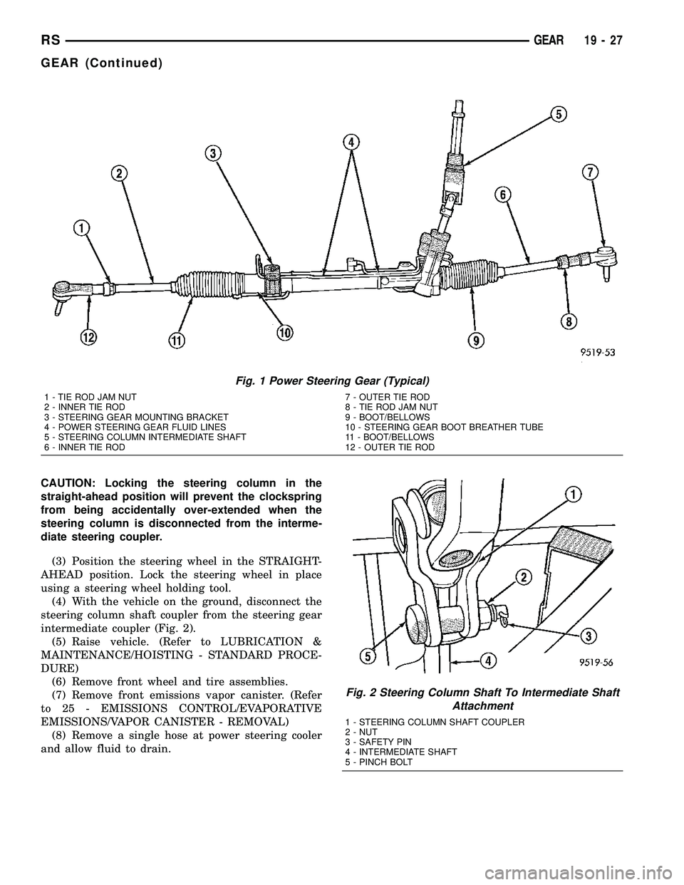
(4) With the vehicle on the ground, disconnect the
steering column shaft coupler from the steering gear
intermediate coupler (Fig. 2).
(5) Raise vehicle. (Refer to LUBRICATION &
MAINTENANCE/HOISTING - STANDARD PROCE-
DURE)
(6) Remove front wheel and tire assemblies.
(7) Remove front emissions vapor canister. (Refer
to 25 - EMISSIONS CONTROL/EVAPORATIVE
EMISSIONS/VAPOR CANISTER - REMOVAL)
(8) Remove a single hose at power steering cooler
and allow fluid to drain.
Fig. 1 Power Steering Gear (Typical)
1 - TIE ROD JAM NUT
2 - INNER TIE ROD
3 - STEERING GEAR MOUNTING BRACKET
4 - POWER STEERING GEAR FLUID LINES
5 - STEERING COLUMN INTERMEDIATE SHAFT
6 - INNER TIE ROD7 - OUTER TIE ROD
8 - TIE ROD JAM NUT
9 - BOOT/BELLOWS
10 - STEERING GEAR BOOT BREATHER TUBE
11 - BOOT/BELLOWS
12 - OUTER TIE ROD
Fig. 2 Steering Column Shaft To Intermediate Shaft
Attachment
1 - STEERING COLUMN SHAFT COUPLER
2 - NUT
3 - SAFETY PIN
4 - INTERMEDIATE SHAFT
5 - PINCH BOLT
RSGEAR19-27
GEAR (Continued)
Page 1436 of 2339
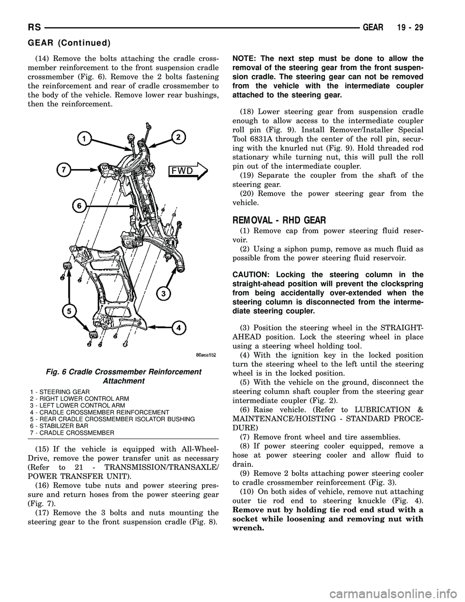
(14) Remove the bolts attaching the cradle cross-
member reinforcement to the front suspension cradle
crossmember (Fig. 6). Remove the 2 bolts fastening
the reinforcement and rear of cradle crossmember to
the body of the vehicle. Remove lower rear bushings,
then the reinforcement.
(15) If the vehicle is equipped with All-Wheel-
Drive, remove the power transfer unit as necessary
(Refer to 21 - TRANSMISSION/TRANSAXLE/
POWER TRANSFER UNIT).
(16) Remove tube nuts and power steering pres-
sure and return hoses from the power steering gear
(Fig. 7).
(17) Remove the 3 bolts and nuts mounting the
steering gear to the front suspension cradle (Fig. 8).NOTE: The next step must be done to allow the
removal of the steering gear from the front suspen-
sion cradle. The steering gear can not be removed
from the vehicle with the intermediate coupler
attached to the steering gear.
(18) Lower steering gear from suspension cradle
enough to allow access to the intermediate coupler
roll pin (Fig. 9). Install Remover/Installer Special
Tool 6831A through the center of the roll pin, secur-
ing with the knurled nut (Fig. 9). Hold threaded rod
stationary while turning nut, this will pull the roll
pin out of the intermediate coupler.
(19) Separate the coupler from the shaft of the
steering gear.
(20) Remove the power steering gear from the
vehicle.
REMOVAL - RHD GEAR
(1) Remove cap from power steering fluid reser-
voir.
(2) Using a siphon pump, remove as much fluid as
possible from the power steering fluid reservoir.
CAUTION: Locking the steering column in the
straight-ahead position will prevent the clockspring
from being accidentally over-extended when the
steering column is disconnected from the interme-
diate steering coupler.
(3) Position the steering wheel in the STRAIGHT-
AHEAD position. Lock the steering wheel in place
using a steering wheel holding tool.
(4) With the ignition key in the locked position
turn the steering wheel to the left until the steering
wheel is in the locked position.
(5) With the vehicle on the ground, disconnect the
steering column shaft coupler from the steering gear
intermediate coupler (Fig. 2).
(6) Raise vehicle. (Refer to LUBRICATION &
MAINTENANCE/HOISTING - STANDARD PROCE-
DURE)
(7) Remove front wheel and tire assemblies.
(8) If power steering cooler equipped, remove a
hose at power steering cooler and allow fluid to
drain.
(9) Remove 2 bolts attaching power steering cooler
to cradle crossmember reinforcement (Fig. 3).
(10) On both sides of vehicle, remove nut attaching
outer tie rod end to steering knuckle (Fig. 4).
Remove nut by holding tie rod end stud with a
socket while loosening and removing nut with
wrench.
Fig. 6 Cradle Crossmember Reinforcement
Attachment
1 - STEERING GEAR
2 - RIGHT LOWER CONTROL ARM
3 - LEFT LOWER CONTROL ARM
4 - CRADLE CROSSMEMBER REINFORCEMENT
5 - REAR CRADLE CROSSMEMBER ISOLATOR BUSHING
6 - STABILIZER BAR
7 - CRADLE CROSSMEMBER
RSGEAR19-29
GEAR (Continued)
Page 1479 of 2339
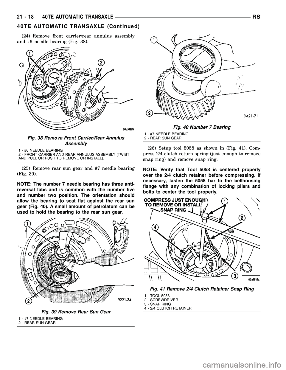
(24) Remove front carrier/rear annulus assembly
and #6 needle bearing (Fig. 38).
(25) Remove rear sun gear and #7 needle bearing
(Fig. 39).
NOTE: The number 7 needle bearing has three anti-
reversal tabs and is common with the number five
and number two position. The orientation should
allow the bearing to seat flat against the rear sun
gear (Fig. 40). A small amount of petrolatum can be
used to hold the bearing to the rear sun gear.(26) Setup tool 5058 as shown in (Fig. 41). Com-
press 2/4 clutch return spring (just enough to remove
snap ring) and remove snap ring.
NOTE: Verify that Tool 5058 is centered properly
over the 2/4 clutch retainer before compressing. If
necessary, fasten the 5058 bar to the bellhousing
flange with any combination of locking pliers and
bolts to center the tool properly.
Fig. 38 Remove Front Carrier/Rear Annulus
Assembly
1 - #6 NEEDLE BEARING
2 - FRONT CARRIER AND REAR ANNULUS ASSEMBLY (TWIST
AND PULL OR PUSH TO REMOVE OR INSTALL).
Fig. 39 Remove Rear Sun Gear
1 - #7 NEEDLE BEARING
2 - REAR SUN GEAR
Fig. 40 Number 7 Bearing
1 - #7 NEEDLE BEARING
2 - REAR SUN GEAR
Fig. 41 Remove 2/4 Clutch Retainer Snap Ring
1 - TOOL 5058
2 - SCREWDRIVER
3 - SNAP RING
4 - 2/4 CLUTCH RETAINER
21 - 18 40TE AUTOMATIC TRANSAXLERS
40TE AUTOMATIC TRANSAXLE (Continued)
Page 1589 of 2339
OPERATION
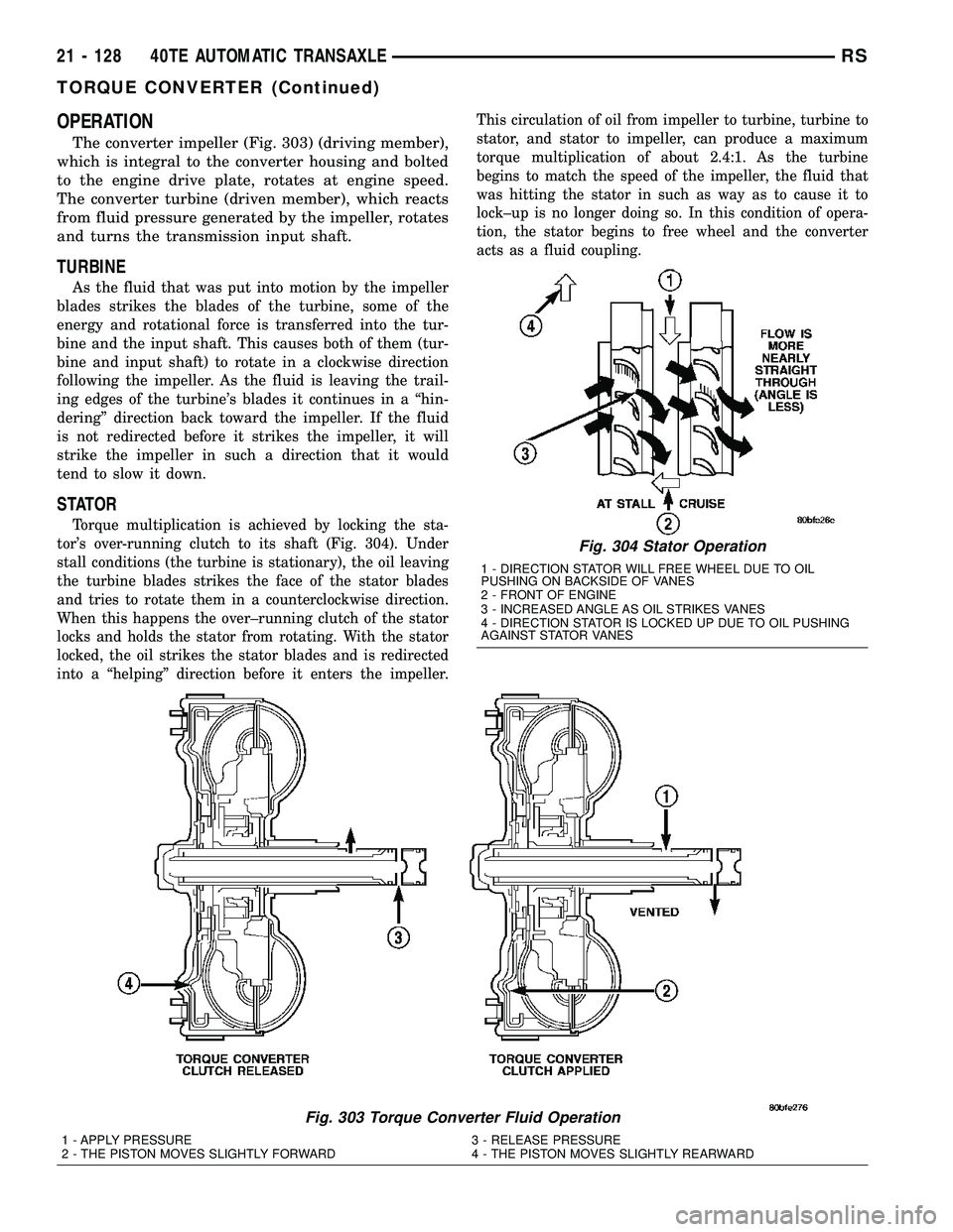
The converter impeller (Fig. 303) (driving member),
which is integral to the converter housing and bolted
to the engine drive plate, rotates at engine speed.
The converter turbine (driven member), which reacts
from fluid pressure generated by the impeller, rotates
and turns the transmission input shaft.
TURBINE
As the fluid that was put into motion by the impeller
blades strikes the blades of the turbine, some of the
energy and rotational force is transferred into the tur-
bine and the input shaft. This causes both of them (tur-
bine and input shaft) to rotate in a clockwise direction
following the impeller. As the fluid is leaving the trail-
ing edges of the turbine's blades it continues in a ªhin-
deringº direction back toward the impeller. If the fluid
is not redirected before it strikes the impeller, it will
strike the impeller in such a direction that it would
tend to slow it down.
STATOR
Torque multiplication is achieved by locking the sta-
tor's over-running clutch to its shaft (Fig. 304). Under
stall conditions (the turbine is stationary), the oil leaving
the turbine blades strikes the face of the stator blades
and tries to rotate them in a counterclockwise direction.
When this happens the over±running clutch of the stator
locks and holds the stator from rotating. With the stator
locked, the oil strikes the stator blades and is redirected
into a ªhelpingº direction before it enters the impeller.This circulation of oil from impeller to turbine, turbine to
stator, and stator to impeller, can produce a maximum
torque multiplication of about 2.4:1. As the turbine
begins to match the speed of the impeller, the fluid that
was hitting the stator in such as way as to cause it to
lock±up is no longer doing so. In this condition of opera-
tion, the stator begins to free wheel and the converter
acts as a fluid coupling.
Fig. 303 Torque Converter Fluid Operation
1 - APPLY PRESSURE 3 - RELEASE PRESSURE
2 - THE PISTON MOVES SLIGHTLY FORWARD 4 - THE PISTON MOVES SLIGHTLY REARWARD
Fig. 304 Stator Operation
1 - DIRECTION STATOR WILL FREE WHEEL DUE TO OIL
PUSHING ON BACKSIDE OF VANES
2 - FRONT OF ENGINE
3 - INCREASED ANGLE AS OIL STRIKES VANES
4 - DIRECTION STATOR IS LOCKED UP DUE TO OIL PUSHING
AGAINST STATOR VANES
21 - 128 40TE AUTOMATIC TRANSAXLERS
TORQUE CONVERTER (Continued)
Page 1624 of 2339

(24) Remove front carrier/rear annulus assembly
and #6 needle bearing (Fig. 38).
(25) Remove rear sun gear and #7 needle bearing
(Fig. 39).
NOTE: The number 7 needle bearing has three anti-
reversal tabs and is common with the number five
and number two position. The orientation should
allow the bearing to seat flat against the rear sun
gear (Fig. 40). A small amount of petrolatum can be
used to hold the bearing to the rear sun gear.(26) Setup tool 5058 as shown in (Fig. 41). Com-
press 2/4 clutch return spring (just enough to remove
snap ring) and remove snap ring.
NOTE: Verify that Tool 5058 is centered properly
over the 2/4 clutch retainer before compressing. If
necessary, fasten the 5058 bar to the bellhousing
flange with any combination of locking pliers and
bolts to center the tool properly.
Fig. 38 Remove Front Carrier and Rear Annulus
Assembly
1 - #6 NEEDLE BEARING
2 - FRONT CARRIER AND REAR ANNULUS ASSEMBLY (TWIST
AND PULL OR PUSH TO REMOVE OR INSTALL).
Fig. 39 Remove Rear Sun Gear
1 - #7 NEEDLE BEARING
2 - REAR SUN GEAR
Fig. 40 Number 7 Bearing
1 - #7 NEEDLE BEARING
2 - REAR SUN GEAR
Fig. 41 Remove 2/4 Clutch Retainer Snap Ring
1 - TOOL 5058
2 - SCREWDRIVER
3 - SNAP RING
4 - 2/4 CLUTCH RETAINER
RS41TE AUTOMATIC TRANSAXLE21 - 163
41TE AUTOMATIC TRANSAXLE (Continued)
Page 1740 of 2339
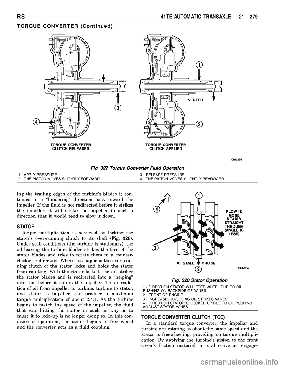
ing the trailing edges of the turbine's blades it con-
tinues in a ªhinderingº direction back toward the
impeller. If the fluid is not redirected before it strikes
the impeller, it will strike the impeller in such a
direction that it would tend to slow it down.
STATOR
Torque multiplication is achieved by locking the
stator's over-running clutch to its shaft (Fig. 328).
Under stall conditions (the turbine is stationary), the
oil leaving the turbine blades strikes the face of the
stator blades and tries to rotate them in a counter-
clockwise direction. When this happens the over±run-
ning clutch of the stator locks and holds the stator
from rotating. With the stator locked, the oil strikes
the stator blades and is redirected into a ªhelpingº
direction before it enters the impeller. This circula-
tion of oil from impeller to turbine, turbine to stator,
and stator to impeller, can produce a maximum
torque multiplication of about 2.4:1. As the turbine
begins to match the speed of the impeller, the fluid
that was hitting the stator in such as way as to
cause it to lock±up is no longer doing so. In this con-
dition of operation, the stator begins to free wheel
and the converter acts as a fluid coupling.
TORQUE CONVERTER CLUTCH (TCC)
In a standard torque converter, the impeller and
turbine are rotating at about the same speed and the
stator is freewheeling, providing no torque multipli-
cation. By applying the turbine's piston to the front
cover's friction material, a total converter engage-
Fig. 327 Torque Converter Fluid Operation
1 - APPLY PRESSURE 3 - RELEASE PRESSURE
2 - THE PISTON MOVES SLIGHTLY FORWARD 4 - THE PISTON MOVES SLIGHTLY REARWARD
Fig. 328 Stator Operation
1 - DIRECTION STATOR WILL FREE WHEEL DUE TO OIL
PUSHING ON BACKSIDE OF VANES
2 - FRONT OF ENGINE
3 - INCREASED ANGLE AS OIL STRIKES VANES
4 - DIRECTION STATOR IS LOCKED UP DUE TO OIL PUSHING
AGAINST STATOR VANES
RS41TE AUTOMATIC TRANSAXLE21 - 279
TORQUE CONVERTER (Continued)
Page 1806 of 2339
INSTALLATION
NOTE: For power sliding door procedures refer to
POWER SLIDING DOOR SYSTEM in the ELECTRI-
CAL section.
(1) Position latch/lock locking lever in unlocked
position.
(2) If equipped, engage wire connector into power
door lock motor (Fig. 4).
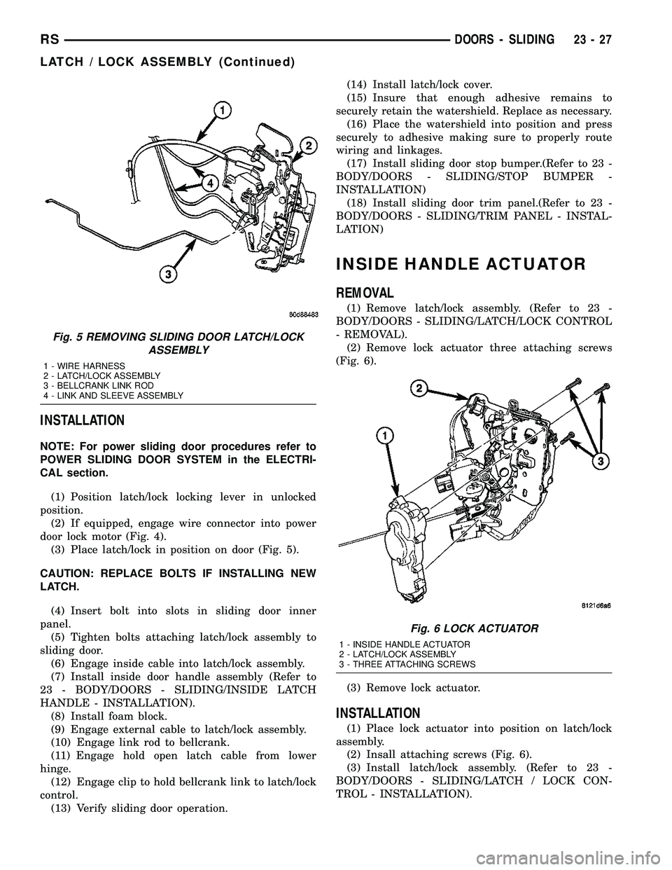
(3) Place latch/lock in position on door (Fig. 5).
CAUTION: REPLACE BOLTS IF INSTALLING NEW
LATCH.
(4) Insert bolt into slots in sliding door inner
panel.
(5) Tighten bolts attaching latch/lock assembly to
sliding door.
(6) Engage inside cable into latch/lock assembly.
(7) Install inside door handle assembly (Refer to
23 - BODY/DOORS - SLIDING/INSIDE LATCH
HANDLE - INSTALLATION).
(8) Install foam block.
(9) Engage external cable to latch/lock assembly.
(10) Engage link rod to bellcrank.
(11) Engage hold open latch cable from lower
hinge.
(12) Engage clip to hold bellcrank link to latch/lock
control.
(13) Verify sliding door operation.(14) Install latch/lock cover.
(15) Insure that enough adhesive remains to
securely retain the watershield. Replace as necessary.
(16) Place the watershield into position and press
securely to adhesive making sure to properly route
wiring and linkages.
(17) Install sliding door stop bumper.(Refer to 23 -
BODY/DOORS - SLIDING/STOP BUMPER -
INSTALLATION)
(18) Install sliding door trim panel.(Refer to 23 -
BODY/DOORS - SLIDING/TRIM PANEL - INSTAL-
LATION)
INSIDE HANDLE ACTUATOR
REMOVAL
(1) Remove latch/lock assembly. (Refer to 23 -
BODY/DOORS - SLIDING/LATCH/LOCK CONTROL
- REMOVAL).
(2) Remove lock actuator three attaching screws
(Fig. 6).
(3) Remove lock actuator.
INSTALLATION
(1) Place lock actuator into position on latch/lock
assembly.
(2) Insall attaching screws (Fig. 6).
(3) Install latch/lock assembly. (Refer to 23 -
BODY/DOORS - SLIDING/LATCH / LOCK CON-
TROL - INSTALLATION).
Fig. 5 REMOVING SLIDING DOOR LATCH/LOCK
ASSEMBLY
1 - WIRE HARNESS
2 - LATCH/LOCK ASSEMBLY
3 - BELLCRANK LINK ROD
4 - LINK AND SLEEVE ASSEMBLY
Fig. 6 LOCK ACTUATOR
1 - INSIDE HANDLE ACTUATOR
2 - LATCH/LOCK ASSEMBLY
3 - THREE ATTACHING SCREWS
RSDOORS - SLIDING23-27
LATCH / LOCK ASSEMBLY (Continued)
Page 1814 of 2339
(6) Engage clip to hold cable end into release han-
dle mechanism.
(7) Place latch handle in position on sliding door.
(8) Install screw to hold top of inside release han-
dle to sliding door.
(9) Install screws to hold bottom of inside latch
handle to sliding door.
(10) Verify sliding door operation. Adjust as neces-
sary. (Refer to 23 - BODY/DOORS - SLIDING/SLID-
ING DOOR - ADJUSTMENTS)
(11) Install sliding door trim panel.(Refer to 23 -
BODY/DOORS - SLIDING/TRIM PANEL - INSTAL-
LATION)
BELLCRANK
REMOVAL
(1) Remove stop bumper (Refer to 23 - BODY/
DOORS - SLIDING/STOP BUMPER - REMOVAL).
(2) Remove sliding door trim panel. (Refer to 23 -
BODY/DOORS - SLIDING/TRIM PANEL -
REMOVAL)
(3) Peel watershield away from adhesive around
perimeter of inner door panel as necessary to gain
access to latch bellcrank.
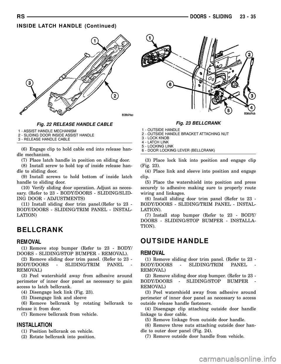
(4) Disengage lock link (Fig. 23).
(5) Disengage link and sleeve
(6) Remove bellcrank by rotating bellcrank to
release it from door.
(7) Remove bellcrank from vehicle.
INSTALLATION
(1) Position bellcrank on vehicle.
(2) Rotate bellcrank into position.(3) Place lock link into position and engage clip
(Fig. 23).
(4) Place link and sleeve into position and engage
clip.
(5) Place the watershield into position and press
securely to adhesive making sure to properly route
wiring and linkages.
(6) Install sliding door trim panel (Refer to 23 -
BODY/DOORS - SLIDING/TRIM PANEL - INSTAL-
LATION).
(7) Install stop bumper (Refer to 23 - BODY/
DOORS - SLIDING/STOP BUMPER - INSTALLA-
TION).
OUTSIDE HANDLE
REMOVAL
(1) Remove sliding door trim panel. (Refer to 23 -
BODY/DOORS - SLIDING/TRIM PANEL -
REMOVAL)
(2) Remove sliding door stop bumper. (Refer to 23 -
BODY/DOORS - SLIDING/STOP BUMPER -
REMOVAL)
(3) Peel watershield away from adhesive around
perimeter of inner door panel as necessary to access
outside release handle fasteners.
(4) Disengage clip attaching outside door handle
linkage to door cable.
(5) Remove linkage from outside door handle.
(6) Remove three nuts attaching outside door han-
dle to outer door panel (Fig. 24).
(7) Remove outside door handle from vehicle.
Fig. 22 RELEASE HANDLE CABLE
1 - ASSIST HANDLE MECHANISM
2 - SLIDING DOOR INSIDE ASSIST HANDLE
3 - RELEASE HANDLE CABLE
Fig. 23 BELLCRANK
1 - OUTSIDE HANDLE
2 - OUTSIDE HANDLE BRACKET ATTACHING NUT
3 - LOCK KNOB
4 - LATCH LINK
5 - LOCKING LINK
6 - DOOR LOCKING LEVER (BELLCRANK)
RSDOORS - SLIDING23-35
INSIDE LATCH HANDLE (Continued)