2005 CHRYSLER VOYAGER Locking
[x] Cancel search: LockingPage 1815 of 2339
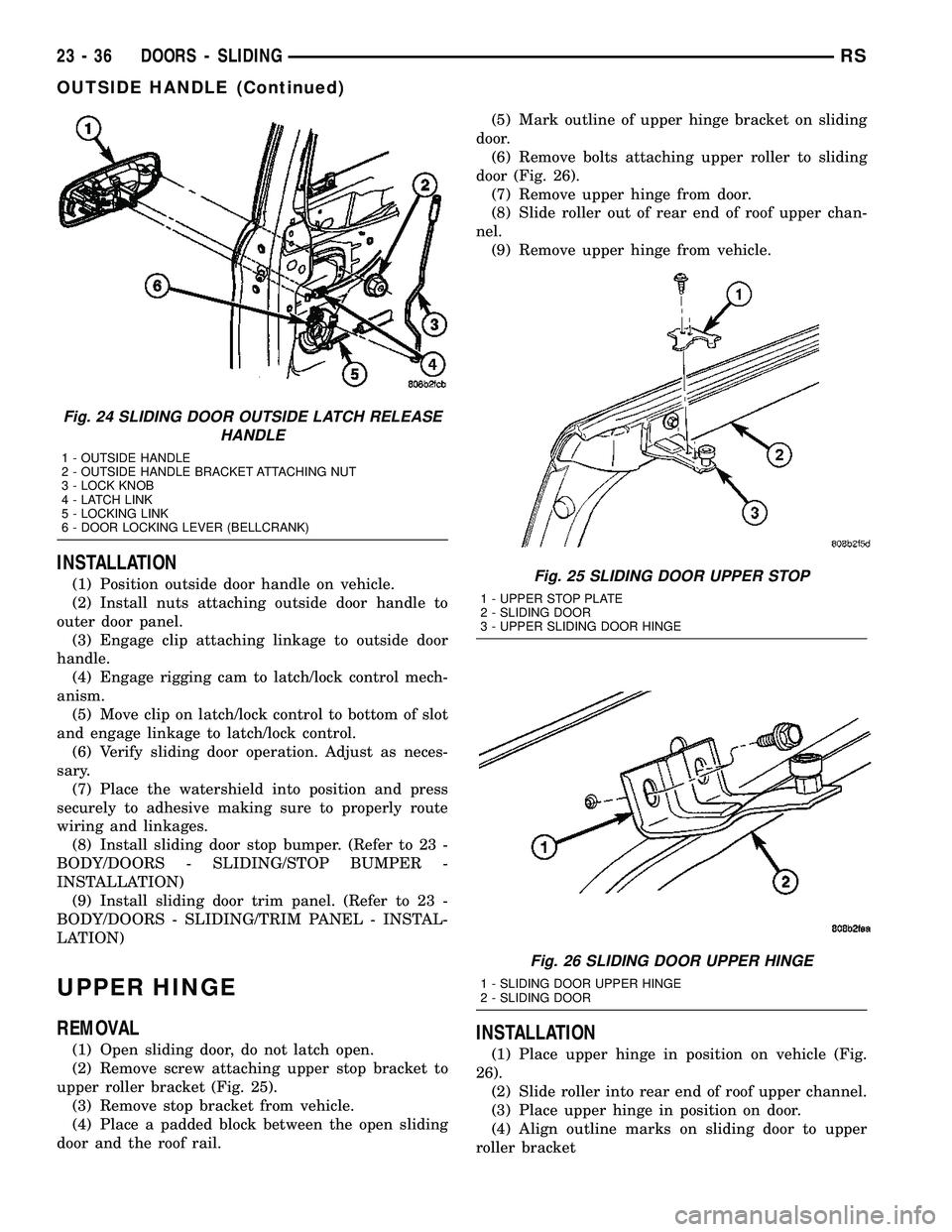
INSTALLATION
(1) Position outside door handle on vehicle.
(2) Install nuts attaching outside door handle to
outer door panel.
(3) Engage clip attaching linkage to outside door
handle.
(4) Engage rigging cam to latch/lock control mech-
anism.
(5) Move clip on latch/lock control to bottom of slot
and engage linkage to latch/lock control.
(6) Verify sliding door operation. Adjust as neces-
sary.
(7) Place the watershield into position and press
securely to adhesive making sure to properly route
wiring and linkages.
(8) Install sliding door stop bumper. (Refer to 23 -
BODY/DOORS - SLIDING/STOP BUMPER -
INSTALLATION)
(9) Install sliding door trim panel. (Refer to 23 -
BODY/DOORS - SLIDING/TRIM PANEL - INSTAL-
LATION)
UPPER HINGE
REMOVAL
(1) Open sliding door, do not latch open.
(2) Remove screw attaching upper stop bracket to
upper roller bracket (Fig. 25).
(3) Remove stop bracket from vehicle.
(4) Place a padded block between the open sliding
door and the roof rail.(5) Mark outline of upper hinge bracket on sliding
door.
(6) Remove bolts attaching upper roller to sliding
door (Fig. 26).
(7) Remove upper hinge from door.
(8) Slide roller out of rear end of roof upper chan-
nel.
(9) Remove upper hinge from vehicle.INSTALLATION
(1) Place upper hinge in position on vehicle (Fig.
26).
(2) Slide roller into rear end of roof upper channel.
(3) Place upper hinge in position on door.
(4) Align outline marks on sliding door to upper
roller bracket
Fig. 24 SLIDING DOOR OUTSIDE LATCH RELEASE
HANDLE
1 - OUTSIDE HANDLE
2 - OUTSIDE HANDLE BRACKET ATTACHING NUT
3 - LOCK KNOB
4 - LATCH LINK
5 - LOCKING LINK
6 - DOOR LOCKING LEVER (BELLCRANK)
Fig. 25 SLIDING DOOR UPPER STOP
1 - UPPER STOP PLATE
2 - SLIDING DOOR
3 - UPPER SLIDING DOOR HINGE
Fig. 26 SLIDING DOOR UPPER HINGE
1 - SLIDING DOOR UPPER HINGE
2 - SLIDING DOOR
23 - 36 DOORS - SLIDINGRS
OUTSIDE HANDLE (Continued)
Page 1842 of 2339
INSTALLATION
(1) Place hood in position on vehicle. With assis-
tance from a helper at the opposite side of the vehicle
to support the hood, install bottom bolts attaching
hood to hinge finger tight.
(2) Install top bolts attaching hood to hinge finger
tight.
(3) Position bolts at marks and tighten. Tighten
bolts to 13.5 N´m (120 in. lbs.) torque. The hood
should be aligned to 4 mm (0.160 in.) gap to the front
fenders and flush across the top surfaces along fend-
ers.
(4) Verify hood operation and alignment.
LATCH
REMOVAL
(1) Release hood latch and open hood.
(2) Remove bolts attaching hood latch to radiator
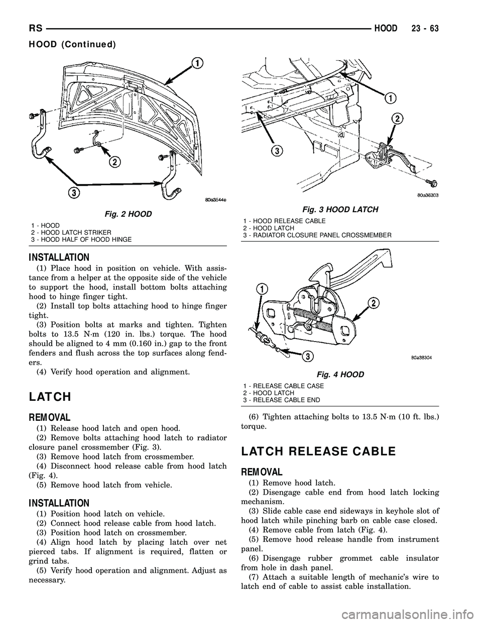
closure panel crossmember (Fig. 3).
(3) Remove hood latch from crossmember.
(4) Disconnect hood release cable from hood latch
(Fig. 4).
(5) Remove hood latch from vehicle.
INSTALLATION
(1) Position hood latch on vehicle.
(2) Connect hood release cable from hood latch.
(3) Position hood latch on crossmember.
(4) Align hood latch by placing latch over net
pierced tabs. If alignment is required, flatten or
grind tabs.
(5) Verify hood operation and alignment. Adjust as
necessary.(6) Tighten attaching bolts to 13.5 N´m (10 ft. lbs.)
torque.
LATCH RELEASE CABLE
REMOVAL
(1) Remove hood latch.
(2) Disengage cable end from hood latch locking
mechanism.
(3) Slide cable case end sideways in keyhole slot of
hood latch while pinching barb on cable case closed.
(4) Remove cable from latch (Fig. 4).
(5) Remove hood release handle from instrument
panel.
(6) Disengage rubber grommet cable insulator
from hole in dash panel.
(7) Attach a suitable length of mechanic's wire to
latch end of cable to assist cable installation.
Fig. 2 HOOD
1 - HOOD
2 - HOOD LATCH STRIKER
3 - HOOD HALF OF HOOD HINGE
Fig. 3 HOOD LATCH
1 - HOOD RELEASE CABLE
2 - HOOD LATCH
3 - RADIATOR CLOSURE PANEL CROSSMEMBER
Fig. 4 HOOD
1 - RELEASE CABLE CASE
2 - HOOD LATCH
3 - RELEASE CABLE END
RSHOOD23-63
HOOD (Continued)
Page 1843 of 2339

(8) Route cable back from latch through engine
compartment toward dash panel near power brake
booster (Fig. 5).
(9) Remove attaching clips from cable case.
(10) From inside vehicle, pull cable through dash
panel until mechanic's wire is exposed.
(11) Disconnect cable from mechanic's wire.
(12) Remove hood release cable from vehicle.
INSTALLATION
(1) Place hood release cable in position under
instrument panel.
(2) Attach latch end of hood release cable to
mechanic's wire protruding through dash panel.
(3) Route cable forward through engine compart-
ment toward latch by pulling on mechanic's wire
(Fig. 5).(4) Disconnect mechanic's wire from cable.
(5) Engage rubber grommet cable insulator into
hole in dash panel.
(6) Install hood release handle into instrument
panel.
(7) Place cable in position on latch.
(8) Slide cable case end sideways into keyhole slot
of hood latch.
(9) Engage cable end into hood latch locking mech-
anism.
(10) Install hood latch.
(11) Install attaching clips to cable case and install
clips into original holes in strut tower, fender, head-
lamp area, and radiator closure panel crossmember.
LATCH STRIKER
REMOVAL
(1) Release hood latch and open hood.
(2) Remove bolts attaching striker to inside of
hood.
(3) Remove hood latch striker from vehicle.
INSTALLATION
(1) Position hood latch striker on vehicle, aligning
with paint breaks.
(2) Install bolts attaching hood latch striker to
hood.
(3) Align hood latch striker to engage smoothly
into hood latch.
(4) Verify hood operation and alignment. Adjust as
necessary.
(5) Tighten attaching bolts to 13.5 N´m (10 ft. lbs.)
torque.Fig. 5 HOOD RELEASE CABLE ROUTING
1 - GROMMET
2 - HOOD RELEASE CABLE
3 - RADIATOR CLOSURE PANEL CROSSMEMBER
23 - 64 HOODRS
LATCH RELEASE CABLE (Continued)
Page 1870 of 2339
HEADLINER
REMOVAL
(1) Remove sun visors and vanity mirrors.
(2) Remove sun visor center supports.
(3) If equipped, remove coat hooks.
(4) If equipped, remove roof rail modules.
(5) Remove A-pillar trim covers. (Refer to 23 -
BODY/INTERIOR/A-PILLAR TRIM - REMOVAL).
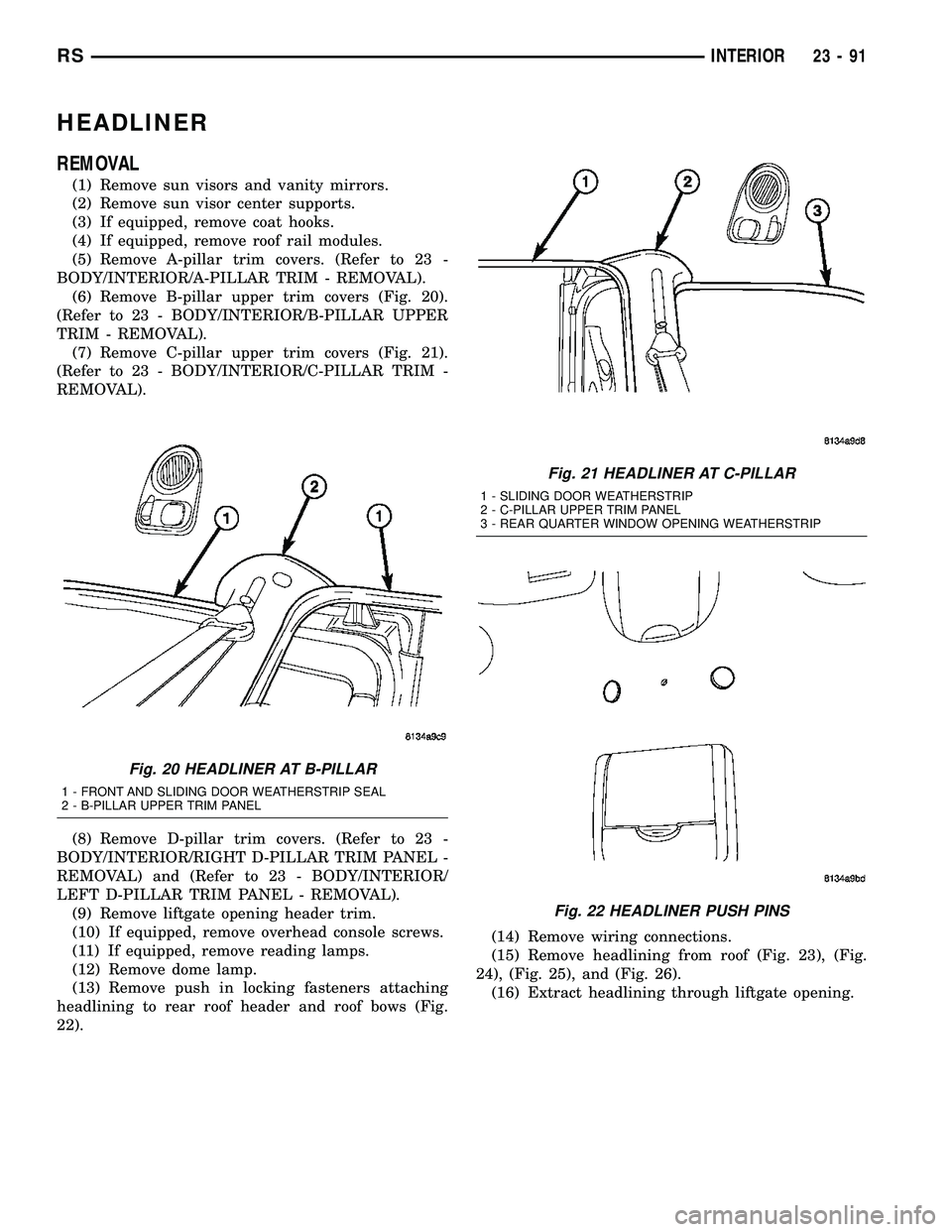
(6) Remove B-pillar upper trim covers (Fig. 20).
(Refer to 23 - BODY/INTERIOR/B-PILLAR UPPER
TRIM - REMOVAL).
(7) Remove C-pillar upper trim covers (Fig. 21).
(Refer to 23 - BODY/INTERIOR/C-PILLAR TRIM -
REMOVAL).
(8) Remove D-pillar trim covers. (Refer to 23 -
BODY/INTERIOR/RIGHT D-PILLAR TRIM PANEL -
REMOVAL) and (Refer to 23 - BODY/INTERIOR/
LEFT D-PILLAR TRIM PANEL - REMOVAL).
(9) Remove liftgate opening header trim.
(10) If equipped, remove overhead console screws.
(11) If equipped, remove reading lamps.
(12) Remove dome lamp.
(13) Remove push in locking fasteners attaching
headlining to rear roof header and roof bows (Fig.
22).(14) Remove wiring connections.
(15) Remove headlining from roof (Fig. 23), (Fig.
24), (Fig. 25), and (Fig. 26).
(16) Extract headlining through liftgate opening.
Fig. 20 HEADLINER AT B-PILLAR
1 - FRONT AND SLIDING DOOR WEATHERSTRIP SEAL
2 - B-PILLAR UPPER TRIM PANEL
Fig. 21 HEADLINER AT C-PILLAR
1 - SLIDING DOOR WEATHERSTRIP
2 - C-PILLAR UPPER TRIM PANEL
3 - REAR QUARTER WINDOW OPENING WEATHERSTRIP
Fig. 22 HEADLINER PUSH PINS
RSINTERIOR23-91
Page 1871 of 2339
INSTALLATION
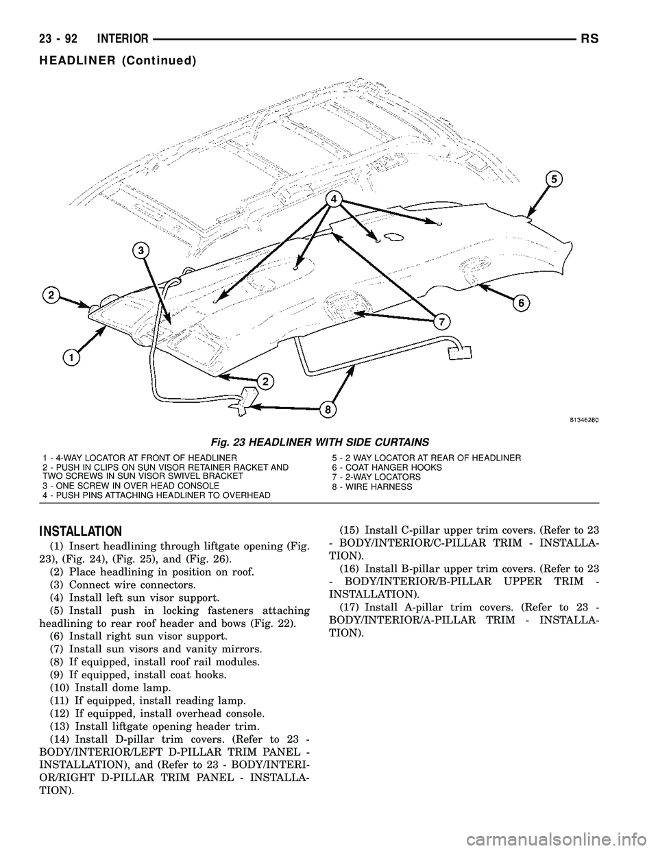
(1) Insert headlining through liftgate opening (Fig.
23), (Fig. 24), (Fig. 25), and (Fig. 26).
(2) Place headlining in position on roof.
(3) Connect wire connectors.
(4) Install left sun visor support.
(5) Install push in locking fasteners attaching
headlining to rear roof header and bows (Fig. 22).
(6) Install right sun visor support.
(7) Install sun visors and vanity mirrors.
(8) If equipped, install roof rail modules.
(9) If equipped, install coat hooks.
(10) Install dome lamp.
(11) If equipped, install reading lamp.
(12) If equipped, install overhead console.
(13) Install liftgate opening header trim.
(14) Install D-pillar trim covers. (Refer to 23 -
BODY/INTERIOR/LEFT D-PILLAR TRIM PANEL -
INSTALLATION), and (Refer to 23 - BODY/INTERI-
OR/RIGHT D-PILLAR TRIM PANEL - INSTALLA-
TION).(15) Install C-pillar upper trim covers. (Refer to 23
- BODY/INTERIOR/C-PILLAR TRIM - INSTALLA-
TION).
(16) Install B-pillar upper trim covers. (Refer to 23
- BODY/INTERIOR/B-PILLAR UPPER TRIM -
INSTALLATION).
(17) Install A-pillar trim covers. (Refer to 23 -
BODY/INTERIOR/A-PILLAR TRIM - INSTALLA-
TION).
Fig. 23 HEADLINER WITH SIDE CURTAINS
1 - 4-WAY LOCATOR AT FRONT OF HEADLINER
2 - PUSH IN CLIPS ON SUN VISOR RETAINER RACKET AND
TWO SCREWS IN SUN VISOR SWIVEL BRACKET
3 - ONE SCREW IN OVER HEAD CONSOLE
4 - PUSH PINS ATTACHING HEADLINER TO OVERHEAD5-2WAYLOCATOR AT REAR OF HEADLINER
6 - COAT HANGER HOOKS
7 - 2-WAY LOCATORS
8 - WIRE HARNESS
23 - 92 INTERIORRS
HEADLINER (Continued)
Page 1882 of 2339
SEAT BASE RISER - SECOND ROW - FOLD-IN-
FLOOR
REMOVAL............................134
INSTALLATION........................135
SEAT CUSHION COVER/FOAM -SECOND ROW
- FOLD-IN-FLOOR
REMOVAL............................136
INSTALLATION........................136
SEAT RECLINER/FORWARD FOLDING
MECHANISM -SECOND ROW -FOLD-IN-
FLOOR
REMOVAL............................137
INSTALLATION........................137
SEAT CUSHION SIDE SHIELD - SECOND ROW
- FOLD-IN-FLOOR
REMOVAL............................138
INSTALLATION........................138
SEAT GAS STRUT - SECOND ROW - FOLD-IN-
FLOOR
REMOVAL............................138
INSTALLATION........................139
SEAT PROP ROD - SECOND ROW - FOLD-IN-
FLOOR
REMOVAL............................139
INSTALLATION........................140
BUCKET SEAT BACK - QUAD BUCKET
REMOVAL............................140
INSTALLATION........................141
QUAD SEAT CUSHION
REMOVAL............................141
INSTALLATION........................141
QUAD BUCKET SEAT SIDE SHIELD/CUP
HOLDER
REMOVAL............................141
INSTALLATION........................142
QUAD BUCKET SEAT SIDE SHIELD - NO CUP
HOLDER
REMOVAL............................143
INSTALLATION........................143
QUAD BUCKET SEAT RISER
REMOVAL............................143
INSTALLATION........................143
BENCH SEAT BACK PANEL
REMOVAL............................143
INSTALLATION........................144
SEAT CUSHION COVER - QUAD BUCKET,
50/50 SPLIT, BENCH
REMOVAL............................144
INSTALLATION........................144
BENCH SEAT RISER - 50/50 SPLIT
REMOVAL............................145
INSTALLATION........................145
BENCH SEAT RISER - SECOND ROW
REMOVAL............................145
INSTALLATION........................145BENCH SEAT RISER - THIRD ROW
REMOVAL............................145
INSTALLATION........................145
SEAT BACK HINGE COVERS - QUAD BUCKET,
50/50 SPLIT, BENCH
REMOVAL............................146
INSTALLATION........................146
BENCH SEAT BACK HINGE
REMOVAL............................146
INSTALLATION
INSTALLATION......................146
SYNCHRONIZING CABLE ADJUSTMENT . . 147
BENCH SEAT BACK
REMOVAL............................147
INSTALLATION........................147
BENCH SEAT BACK COVER
REMOVAL............................148
INSTALLATION........................148
BENCH SEAT TRACK
REMOVAL............................148
INSTALLATION........................148
PLASTIC GROCERY BAG RETAINER
REMOVAL............................149
INSTALLATION........................149
UNDER SEAT STORAGE BIN
REMOVAL............................149
INSTALLATION........................149
UNDER SEAT STORAGE BIN GUIDE
REMOVAL............................150
INSTALLATION........................150
UNDER SEAT STORAGE BIN LOCK/LATCH
REMOVAL............................150
INSTALLATION........................150
LUMBAR SUPPORT
REMOVAL............................150
INSTALLATION........................150
SEAT RISER LATCH LOCKING LINK
REMOVAL............................151
INSTALLATION........................151
QUAD BUCKET SEAT SIDE SHIELD/CUP
HOLDER - FLAP AND SPRING ASSEMBLY
REMOVAL............................151
INSTALLATION........................151
BOTTOM OF SEAT CUSHION PAN PANEL-
THIRD ROW - FOLD-IN-FLOOR
REMOVAL............................152
INSTALLATION........................152
HEADREST SLEEVE - THIRD ROW - FOLD-IN-
FLOOR
REMOVAL............................152
INSTALLATION........................153
SEAT - THIRD ROW - FOLD-IN-FLOOR
REMOVAL............................153
INSTALLATION........................154
RSSEATS23 - 103
Page 1884 of 2339
INSTALLATION
INSTALLATION
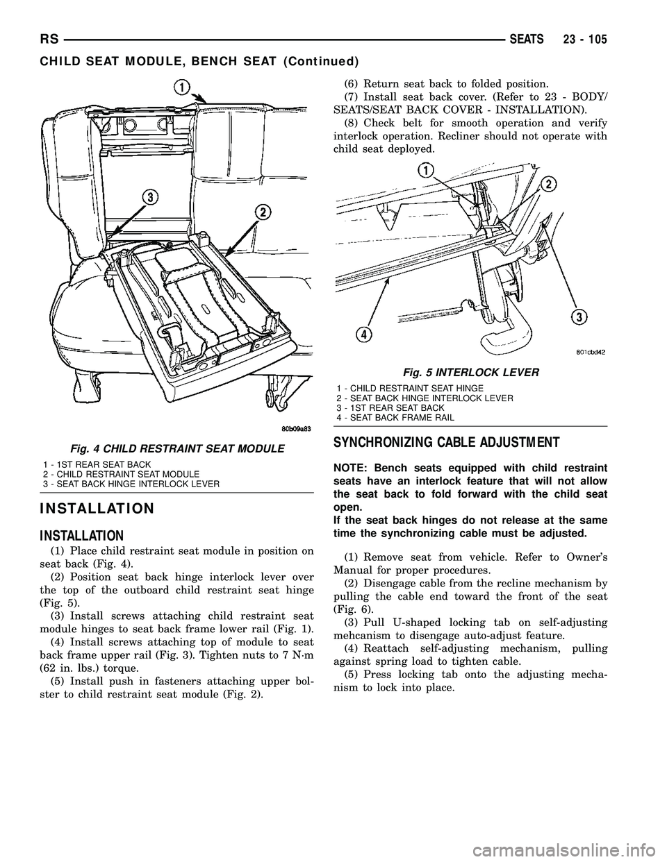
(1) Place child restraint seat module in position on
seat back (Fig. 4).
(2) Position seat back hinge interlock lever over
the top of the outboard child restraint seat hinge
(Fig. 5).
(3) Install screws attaching child restraint seat
module hinges to seat back frame lower rail (Fig. 1).
(4) Install screws attaching top of module to seat
back frame upper rail (Fig. 3). Tighten nuts to 7 N´m
(62 in. lbs.) torque.
(5) Install push in fasteners attaching upper bol-
ster to child restraint seat module (Fig. 2).(6) Return seat back to folded position.
(7) Install seat back cover. (Refer to 23 - BODY/
SEATS/SEAT BACK COVER - INSTALLATION).
(8) Check belt for smooth operation and verify
interlock operation. Recliner should not operate with
child seat deployed.
SYNCHRONIZING CABLE ADJUSTMENT
NOTE: Bench seats equipped with child restraint
seats have an interlock feature that will not allow
the seat back to fold forward with the child seat
open.
If the seat back hinges do not release at the same
time the synchronizing cable must be adjusted.
(1) Remove seat from vehicle. Refer to Owner's
Manual for proper procedures.
(2) Disengage cable from the recline mechanism by
pulling the cable end toward the front of the seat
(Fig. 6).
(3) Pull U-shaped locking tab on self-adjusting
mehcanism to disengage auto-adjust feature.
(4) Reattach self-adjusting mechanism, pulling
against spring load to tighten cable.
(5) Press locking tab onto the adjusting mecha-
nism to lock into place.
Fig. 4 CHILD RESTRAINT SEAT MODULE
1 - 1ST REAR SEAT BACK
2 - CHILD RESTRAINT SEAT MODULE
3 - SEAT BACK HINGE INTERLOCK LEVER
Fig. 5 INTERLOCK LEVER
1 - CHILD RESTRAINT SEAT HINGE
2 - SEAT BACK HINGE INTERLOCK LEVER
3 - 1ST REAR SEAT BACK
4 - SEAT BACK FRAME RAIL
RSSEATS23 - 105
CHILD SEAT MODULE, BENCH SEAT (Continued)
Page 1885 of 2339
QUAD CHILD SEAT
REMOVAL
(1) Remove the seat. Refer to Owner's Manual for
proper procedures.
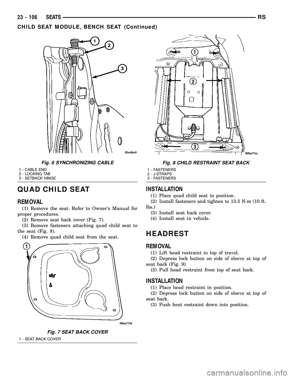
(2) Remove seat back cover (Fig. 7).
(3) Remove fasteners attaching quad child seat to
the seat (Fig. 8).
(4) Remove quad child seat from the seat.
INSTALLATION
(1) Place quad child seat in position.
(2) Install fasteners and tighten to 13.5 N´m (10 ft.
lbs.)
(3) Install seat back cover.
(4) Install seat in vehicle.
HEADREST
REMOVAL
(1) Lift head restraint to top of travel.
(2) Depress lock button on side of sleeve at top of
seat back (Fig. 9).
(3) Pull head restraint from top of seat back.
INSTALLATION
(1) Place head restraint in position.
(2) Depress lock button on side of sleeve at top of
seat back.
(3) Push heat restraint down into position.
Fig. 6 SYNCHRONIZING CABLE
1 - CABLE END
2 - LOCKING TAB
3 - SETBACK HINGE
Fig. 7 SEAT BACK COVER
1 - SEAT BACK COVER
Fig. 8 CHILD RESTRAINT SEAT BACK
1 - FASTENERS
2 - J-STRAPS
3 - FASTENERS
23 - 106 SEATSRS
CHILD SEAT MODULE, BENCH SEAT (Continued)