2005 CHRYSLER VOYAGER Locking
[x] Cancel search: LockingPage 475 of 2339

NOTE: Push in on the push-pins at the clutch hous-
ing (plastic side) until you hear one click. Push in
on the push-pin fasteners at the motor mount
(sheet metal side) until you hear two clicks. This
assures proper installation/attachment of the motor
to the sliding door.
(3) Install the flex shaft by lining up the square
shaped drive shaft with the corresponding hole in the
door motor drive unit and push straight in.
(4) Install the E-clip to secure flex-shaft.
(5) Install the weather shield as necessary.
(6) Install the door trim panel on the sliding door,
(Refer to 23 - BODY/DOORS - SLIDING/TRIM
PANEL - INSTALLATION) for the procedure.
(7) Connect the battery negative cable.
FULL OPEN SWITCH
DESCRIPTION
The full open switch is located in the hold open
latch (Fig. 10) under the sliding door lower hinge.
When the power sliding door control module receives
a ground signal input from the full open switch, and
as long as the cinching latch actuator is not in power
mode or the handle switch is open, the signal indi-
cates that the door is at the full open position.The full open switch is incorporated into the hold
open latch. If the full open switch is inoperative, the
entire hold open latch assembly must be replaced.
OPERATION
The full open switch is triggered by a pawl lever in
the hold open latch. When the full open switch is
closed (circuit to ground) the ratchet has engaged on
the hold open striker and the pawl lever has engaged
on the ratchet, locking the latch from opening and
holding the door in the full open position.
B-PILLAR SWITCH
DESCRIPTION
The B-pillar switches are located on the interior of
the vehicle, on the B-pillar trim panels. These
switches serve as an open and close command switch
for the appropriate power sliding door.
OPERATION
When the B-pillar switch is depressed a signal is
sent to the Body Control Module (BCM), this signal
is then sent to the power sliding door control module,
telling it to start a power open or close cycle. The
child lockout feature must be disabled and the slid-
ing door must be unlocked in order for the B-pillar
switch to function.
REMOVAL
(1) Disconnect and isolate the battery negative
cable.
(2) Using a trim stick (special tool # C-4755) or
equivalent, gently pry the leading upper edge of the
B-pillar switch away from the B-pillar trim.
(3) Once the upper edge is free from B-pillar trim,
rock the switch out of the switch opening.
(4) Disconnect the B-pillar switch electrical con-
nector. First, slide the connector lock away from the
switch then, depress connector retaining tab while
pulling straight apart.
(5) Remove the B-pillar switch from the vehicle.
INSTALLATION
(1) Connect the B-pillar switch electrical connector.
Slide connector lock toward the switch to lock in
place.
(2) Hook the lower edge of the B-pillar switch on
the B-pillar trim and then push the switch firmly
into position.
(3) Connect the battery negative cable.
Fig. 10 FULL OPEN SWITCH POSITION &
ORIENTATION
1 - HOLD OPEN LATCH ASSEMBLY
2 - HOLD OPEN LATCH CABLE
3 - FULL OPEN SWITCH
8N - 52 POWER SLIDING DOOR SYSTEMRS
SLIDING DOOR MOTOR (Continued)
Page 487 of 2339

REMOVAL
(1) Disconnect and isolate the battery negative
cable.
(2) Using a trim stick, start at the bottom of the
switch and bezel assembly and pry up to remove the
switch and bezel assembly from the door trim panel
(Fig. 4).
(3) Unlatch the locking tab on the harness side
connector of the switch.
(4) Disconnect wire harness connectors from
switch.
INSTALLATION
(1) Reconnect wire harness connector to switch.
(2) Insert switch into door trim panel and press
into place.
(3) Reconnect battery negative cable.
Fig. 4 POWER WINDOW SWITCH
1 - DOOR TRIM PANEL
2 - POWER WINDOW SWITCH AND BEZEL ASSEMBLY
8N - 64 POWER WINDOWSRS
WINDOW SWITCH (Continued)
Page 539 of 2339

RG Only- If fault is detected on the driver key
cylinder input, the indicator LED will remain solid
during the arming process, although the system will
still arm.
If the indicator LED does not illuminate at all
upon door closing it indicates that the system is not
arming.
Passive disarming occurs upon normal vehicle
entry by unlocking either door with the remote trans-
mitter (RG - ignition key or remote transmitter). This
disarming will also halt the alarm once it has been
activated.
A tamper alert exists to notify the driver that the
VTSS had been activated. This alert consists of 3
horn pulses when the vehicle is disarmed.
NOTE: The VTSS will not arm by pushing down the
door lock mechanism. This will manually override
the system.
RG Only- For Door Cylinder Lock Switch
Removal and Installation, refer to Electrical, Power
Locks, Door Cylinder Lock Switch.
If the VTSS is triggered, the horn will pulse, head-
lamps/marker lamps will flash, and the VTSS warn-
ing lamp will flash. If BCM determines the threat to
be false and the VTSS is not triggered again, the sys-
tem will shut down and rearm itself after three min-
utes. If a trigger is still active, the alarm will
continue for an additional 15 minutes without the
horn. The VTSS monitors the passenger compart-
ment (for RG - Export it also monitors the engine
compartment. If a malfunction occurs in the engine
compartment, the passenger compartment would still
arm and function normally).
NOTE: System will not arm if passenger compart-
ment is not secure.
NOTE: (RG - Export - If hood is not secure during
the arming sequence, the lamp will stay lit and not
flash. The system will arm with hood not secured
and the liftgate open).
ARMING THE VTSS - METHOD A
(1) With the key removed from the ignition lock
and any door open (excluding liftgate), actuate one of
the following:
²Power door lock button to LOCK,
²Key fob LOCK button
²Driver door lock key cylinder to locked position
(RG Only).
(2) Close all opened doors. Liftgate can remain
open.(3) After the last door is closed, an arming time-
out period of sixteen seconds will start, then the
VTSS will become armed.
ARMING THE VTSS - METHOD B
Actuating the key fob transmitter LOCK button,
key locking the front doors with the doors closed and
the ignition locked will begin the arming time-out
period. If method A, 16 second time-out sequence was
in process when method B was actuated, the 16 sec-
ond time-out will restart from the time of the second
actuation.
If the security lamp does not illuminate at all upon
final door closure, it indicates that the system is not
arming.
The current VTSS status armed or disarmed shall
be maintained in memory to prevent battery discon-
nects from disarming the system.
TRIGGERING THE VTSS
After the VTSS is armed, the following actions will
trigger the alarm:
²Opening any door (liftgate - only if opening via
liftgate button on key fob).
²Opening the hood (RG - Export)
²Turning the ignition to the RUN position.
NOTE: When the VTSS is ARMED, the interior
power door lock switch ªUNLOCKº will be disabled
until the vehicle is disarmed.
CAUTION: The VTSS indicator LED will trigger and
engine will continue to run if the vehicle is
equipped with SKREES and the proper key is used
to start the vehicle. This condition will occur if the
VTSS has been triggered. If valid key is used, VTSS
will disarm
SENTRY KEY REMOTE ENTRY SYSTEM
The SKREES includes keys from the factory which
are pre-programmed. Each SKREEM will recognize a
maximum of eight Sentry Keys. If the customer
would like to own additional keys other than those
provided with the vehicle, they can be purchased
from any authorized dealer. These keys must be pro-
grammed to the SKREEM on the vehicle in order for
the system to recognize them as valid keys. This can
be done by the dealer with a DRBllltscan tool or by
a customer if this feature is available in their market
and they have two (2) valid keys already available to
them. Refer to the Service Procedures portion of this
system for additional details. The SKREES performs
a self-test each time the ignition switch is turned to
the ON position and will store Diagnostic Trouble
Codes (DTC's) if a system malfunction is detected.
8Q - 2 VEHICLE THEFT SECURITYRS
VEHICLE THEFT SECURITY (Continued)
Page 576 of 2339

CONNECTOR
REMOVAL
(1) Disconnect battery.
(2) Release Connector Lock (Fig. 10).
(3) Disconnect the connector being repaired from
its mating half/component.
(4) Remove the dress cover (if applicable) (Fig. 10).
(5) Release the Secondary Terminal Lock, if
required (Fig. 11).
(6) Position the connector locking finger away from
the terminal using the proper special tool. Pull on
the wire to remove the terminal from the connector
(Fig. 12).
INSTALLATION
(1) Insert the removed terminal in the same cavity
on the repair connector.
(2) Repeat steps for each terminal in the connec-
tor, being sure that all wires are inserted into the
proper cavities. For additional connector pin-out
identification, refer to the wiring diagrams.
(3) When the connector is re-assembled, the sec-
ondary terminal lock must be placed in the locked
position to prevent terminal push out.
(4) Replace dress cover (if applicable).
(5) Connect connector to its mating half/compo-
nent.
(6) Connect battery and test all affected systems.
Fig. 10 REMOVAL OF DRESS COVER
1 - DRESS COVER
2 - CONNECTOR LOCK
3 - CONNECTOR
RS8W-01 WIRING DIAGRAM INFORMATION8W-01-11
Page 579 of 2339

DIODE
REMOVAL
(1) Disconnect the battery.
(2) Locate the diode in the harness, and remove
the protective covering.
(3) Remove the diode from the harness, pay atten-
tion to the current flow direction (Fig. 13).
INSTALLATION
(1) Remove the insulation from the wires in the
harness. Only remove enough insulation to solder in
the new diode.
(2) Install the new diode in the harness, making
sure current flow is correct. If necessary, refer to the
appropriate wiring diagram for current flow (Fig. 13).
(3) Solder the connection together using rosin core
type solder only.Do not use acid core solder.
(4) Tape the diode to the harness using electrical
tape. Make sure the diode is completely sealed from
the elements.
(5) Re-connect the battery and test affected sys-
tems.
TERMINAL
REMOVAL
(1) Follow steps for removing terminals described
in the connector removal section.
(2) Cut the wire 6 inches from the back of the con-
nector.
INSTALLATION
(1) Select a wire from the terminal repair kit that
best matches the color and gage of the wire being
repaired.
(2) Cut the repair wire to the proper length and
remove one±half (1/2) inch of insulation.
(3) Splice the repair wire to the wire harness (see
wire splicing procedure).
(4) Insert the repaired wire into the connector.
(5) Install the connector locking wedge, if required,
and reconnect the connector to its mating half/compo-
nent.
(6) Re-tape the wire harness starting at 1±1/2
inches behind the connector and 2 inches past the
repair.
(7) Connect battery and test all affected systems.
Fig. 13 DIODE IDENTIFICATION
1 - CURRENT FLOW
2 - BAND AROUND DIODE INDICATES CURRENT FLOW
3 - DIODE AS SHOWN IN THE DIAGRAMS
8W - 01 - 14 8W-01 WIRING DIAGRAM INFORMATIONRS
Page 1352 of 2339

REAR BUMPER
REINFORCEMENT
REMOVAL
(1) Remove rear bumper fascia. (Refer to 13 -
FRAMES & BUMPERS/BUMPERS/REAR FASCIA -
REMOVAL)
(2) Support rear bumper reinforcement on a suit-
able lifting device.
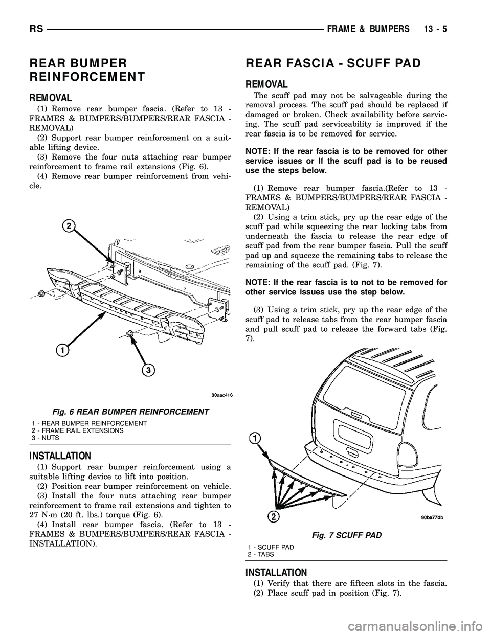
(3) Remove the four nuts attaching rear bumper
reinforcement to frame rail extensions (Fig. 6).
(4) Remove rear bumper reinforcement from vehi-
cle.
INSTALLATION
(1) Support rear bumper reinforcement using a
suitable lifting device to lift into position.
(2) Position rear bumper reinforcement on vehicle.
(3) Install the four nuts attaching rear bumper
reinforcement to frame rail extensions and tighten to
27 N´m (20 ft. lbs.) torque (Fig. 6).
(4) Install rear bumper fascia. (Refer to 13 -
FRAMES & BUMPERS/BUMPERS/REAR FASCIA -
INSTALLATION).
REAR FASCIA - SCUFF PAD
REMOVAL
The scuff pad may not be salvageable during the
removal process. The scuff pad should be replaced if
damaged or broken. Check availability before servic-
ing. The scuff pad serviceability is improved if the
rear fascia is to be removed for service.
NOTE: If the rear fascia is to be removed for other
service issues or If the scuff pad is to be reused
use the steps below.
(1) Remove rear bumper fascia.(Refer to 13 -
FRAMES & BUMPERS/BUMPERS/REAR FASCIA -
REMOVAL)
(2) Using a trim stick, pry up the rear edge of the
scuff pad while squeezing the rear locking tabs from
underneath the fascia to release the rear edge of
scuff pad from the rear bumper fascia. Pull the scuff
pad up and squeeze the remaining tabs to release the
remaining of the scuff pad. (Fig. 7).
NOTE: If the rear fascia is to not to be removed for
other service issues use the step below.
(3) Using a trim stick, pry up the rear edge of the
scuff pad to release tabs from the rear bumper fascia
and pull scuff pad to release the forward tabs (Fig.
7).
INSTALLATION
(1) Verify that there are fifteen slots in the fascia.
(2) Place scuff pad in position (Fig. 7).
Fig. 6 REAR BUMPER REINFORCEMENT
1 - REAR BUMPER REINFORCEMENT
2 - FRAME RAIL EXTENSIONS
3 - NUTS
Fig. 7 SCUFF PAD
1 - SCUFF PAD
2 - TABS
RSFRAME & BUMPERS13-5
Page 1370 of 2339

FUEL LEVEL SENDING UNIT /
SENSOR
DESCRIPTION
The fuel gauge level sending unit is attached to the
side of fuel pump module. The level sensor is a vari-
able resistor.
OPERATION
Its resistance changes with the amount of fuel in
the tank. The float arm attached to the sensor moves
as the fuel level changes.
The fuel level input is used as an input for OBD II.
If the fuel level is below 15% or above 85% of total
tank capacity several monitors are disabled. There
are diagnostics for the level circuit open and shorted.
REMOVAL
Remove fuel pump module. Refer to Fuel Pump
Module in this section.
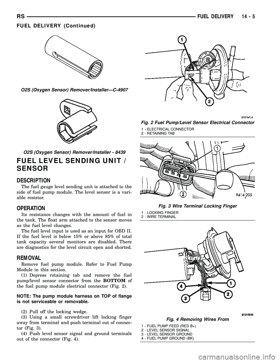
(1) Depress retaining tab and remove the fuel
pump/level sensor connector from theBOTTOMof
the fuel pump module electrical connector (Fig. 2).
NOTE: The pump module harness on TOP of flange
is not serviceable or removable.
(2) Pull off the locking wedge.
(3) Using a small screwdriver lift locking finger
away from terminal and push terminal out of connec-
tor (Fig. 3).
(4) Push level sensor signal and ground terminals
out of the connector (Fig. 4).
O2S (Oxygen Sensor) Remover/InstallerÐC-4907
O2S (Oxygen Sensor) Remover/Installer - 8439
Fig. 2 Fuel Pump/Level Sensor Electrical Connector
1 - ELECTRICAL CONNECTOR
2 - RETAINING TAB
Fig. 3 Wire Terminal Locking Finger
1 - LOCKING FINGER
2 - WIRE TERMINAL
Fig. 4 Removing Wires From
1 - FUEL PUMP FEED (RED B+)
2 - LEVEL SENSOR SIGNAL
3 - LEVEL SENSOR GROUND
4 - FUEL PUMP GROUND (BK)
RSFUEL DELIVERY14-5
FUEL DELIVERY (Continued)
Page 1372 of 2339

(4) Install level sensor wires in connector. Push
the wires up through the connector and then pull
them down until they lock in place. Ensure signal
and ground wires are installed in the correct posi-
tion.
(5) Install locking wedge on connector.
(6) Push connector up into bottom of fuel pump
module electrical connector.
(7) Install fuel pump module. Refer to Fuel Pump
Module in this section.
FUEL LINES
DESCRIPTION - FUEL LINES/HOSES AND
CLAMPS
Also refer to Quick-Connect Fittings.
WARNING: THE FUEL SYSTEM IS UNDER A CON-
STANT PRESSURE (EVEN WITH THE ENGINE OFF).
BEFORE SERVICING ANY FUEL SYSTEM HOSES,
FITTINGS OR LINES, THE FUEL SYSTEM PRES-
SURE MUST BE RELEASED. REFER TO THE FUEL
SYSTEM PRESSURE RELEASE PROCEDURE IN
THIS GROUP. THIS MAY RESULT IN PERSONAL
INJURY OR DEATH.
The lines/tubes/hoses used on fuel injected vehicles
are of a special construction. This is due to the
higher fuel pressures and the possibility of contami-
nated fuel in this system. If it is necessary to replace
these lines/tubes/hoses, use new original equipment
lines/tubes/hoses.
If equipped:The hose clamps used to secure rub-
ber hoses on vehicles are of a special rolled edge con-
struction. This construction is used to prevent the
edge of the clamp from cutting into the hose. Only
these rolled edge type clamps may be used in this
system. All other types of clamps may cut into the
hoses and cause leaks.
Use new original equipment type hose clamps.
STANDARD PROCEDURE - HOSES AND CLAMP
Inspect all hose connections (clamps and quick con-
nect fittings) for completeness and leaks. Replace
cracked, scuffed, or swelled hoses. Replace hoses that
rub against other vehicle components or show sign of
wear.
Fuel injected vehicles use specially constructed
hoses. When replacing hoses, only use hoses marked
EFM/EFI.
When installing hoses, ensure that they are routed
away from contact with other vehicle components
that could rub against them and cause failure. Avoid
contact with clamps or other components that causeabrasions or scuffing. Ensure that rubber hoses are
properly routed and avoid heat sources.
The hose clamps have rolled edges to prevent the
clamp from cutting into the hose. Only use clamps
that are original equipment or equivalent. Other
types of clamps may cut into the hoses and cause
high pressure fuel leaks. Tighten hose clamps to 1
N´m (9 in. lbs.) torque.
Inspect all hose connections such as clamps, cou-
plings and fittings to make sure they are secure and
leaks are not present. The component should be
replaced immediately if there is any evidence of deg-
radation that could result in failure.
Never attempt to repair a plastic fuel line/tube.
Replace as necessary.
Avoid contact of any fuel tubes/hoses with other
vehicle components that could cause abrasions or
scuffing. Be sure that the plastic fuel lines/tubes are
properly routed to prevent pinching and to avoid heat
sources.
FUEL PRESSURE REGULATOR
OPERATION
The fuel system uses a nonadjustable pressure reg-
ulator that maintains fuel system pressure at
approximately 400 34 kPa (58 5 psi). The fuel
pressure regulator contains a diaphragm, calibrated
spring and a fuel return valve. The spring pushes
down on the diaphragm and closes off the fuel return
port. System fuel pressure reflects the amount of fuel
pressure required to open the return port.
The pressure regulator is a mechanical device that
is NOT controlled by the PCM or engine vacuum.
REMOVAL
The fuel pressure regulator is part of the fuel
pump module (Fig. 9). Remove the fuel pump module
from the fuel tank to access the fuel pressure regula-
tor. Refer to the Fuel Pump Module removal in this
section.
(1) Squeeze tangs on pressure regulator retainer
and pull to remove retainer.
(2) Pry fuel pressure regulator out of housing.
(3) Ensure both upper and lower O-rings were
removed with regulator.
INSTALLATION
The fuel pressure regulator is part of the fuel
pump module. Remove the fuel pump module from
the fuel tank to access the fuel pressure regulator.
Refer to the Fuel Pump Module removal in this sec-
tion.
RSFUEL DELIVERY14-7
FUEL LEVEL SENDING UNIT / SENSOR (Continued)