2005 CHRYSLER VOYAGER diagram
[x] Cancel search: diagramPage 206 of 2339

(2) Disconnect traction control switch harness from
column harness (Fig. 5).
(3) Using an ohmmeter, check for continuity
between pins 1 and 2. With the switch actuated,
there should be continuity between the two pins.
With the switch off, there should be no continuity.
REMOVAL
The traction control switch is located in the upper
shroud. (Refer to 19 - STEERING/COLUMN/UPPER
SHROUD - REMOVAL)
INSTALLATION
The traction control switch is located in the upper
shroud. (Refer to 19 - STEERING/COLUMN/UPPER
SHROUD - INSTALLATION)
HYDRAULIC/MECHANICAL
OPERATION - HYDRAULIC CIRCUITS AND
VALVES
The hydraulic fluid control valves control the flow
of pressurized brake fluid to the wheel brakes during
the different modes of ABS braking. The following
paragraphs explain how this works. For purposes of
explanation only, it is assumed that only the right
front wheel is experiencing antilock braking; the fol-
lowing diagrams show only the right front wheel in
an antilock braking operation.
NORMAL BRAKING HYDRAULIC CIRCUIT AND
SOLENOID VALVE FUNCTION
The hydraulic diagram (Fig. 6) shows the vehicle in
the normal braking mode of the base brake hydraulic
system. The diagram shows no wheel spin or slip
occurring relative to the speed of the vehicle. The
driver is applying the brake pedal which builds pres-
sure in the brake hydraulic system to engage the
brakes and stop the vehicle.
Fig. 6 Normal Braking Hydraulic Circuit
1 - OUTLET VALVE
2 - PUMP PISTON
3 - PUMP MOTOR (OFF)
4 - LOW PRESSURE ACCUMULATOR
5 - NORMALLY CLOSED VALVE (OFF)6 - TO RIGHT FRONT WHEEL
7 - NORMALLY OPEN VALVE (OFF)
8 - MASTER CYLINDER PRESSURE
9 - FROM MASTER CYLINDER
10 - NOISE DAMPER CHAMBER
RSBRAKES - ABS5-95
TRACTION CONTROL SWITCH (Continued)
Page 207 of 2339

ABS PRIMARY HYDRAULIC CIRCUIT AND
SOLENOID VALVE FUNCTION (ABS WITHOUT
TRACTION CONTROL)
The hydraulic diagram (Fig. 7) shows the vehicle in
the ABS braking mode. The diagram shows one
wheel is slipping because the driver is attempting to
stop the vehicle at a faster rate than is allowed by
the surface on which the tires are riding.
²The normally open and normally closed valves
modulate (build/decay) the brake hydraulic pressure
as required.
²The pump/motor is switched on so that the
brake fluid from the low pressure accumulators is
returned to the master cylinder circuits.
²The brake fluid is routed to either the master
cylinder or the wheel brake depending on the posi-
tion of the normally open valve.
Fig. 7 ABS Without Traction Control - Primary Hydraulic Circuit
1 - OUTLET VALVE
2 - PUMP PISTON
3 - PUMP MOTOR (ON)
4 - LOW PRESSURE ACCUMULATOR PRESSURE
5 - LOW PRESSURE ACCUMULATOR
6 - NORMALLY CLOSED VALVE (MODULATING)
7 - TO RIGHT FRONT WHEEL8 - NORMALLY OPEN VALVE (MODULATING)
9 - FROM MASTER CYLINDER
10 - MASTER CYLINDER PRESSURE
11 - CONTROLLED WHEEL PRESSURE
12 - PUMP INTERSTAGE PRESSURE
13 - NOISE DAMPER CHAMBER
5 - 96 BRAKES - ABSRS
HYDRAULIC/MECHANICAL (Continued)
Page 208 of 2339

ABS SECONDARY HYDRAULIC CIRCUIT AND
SOLENOID VALVE FUNCTION (ABS WITHOUT
TRACTION CONTROL)
The hydraulic diagram (Fig. 8) shows the vehicle in
the ABS braking mode. The diagram shows one
wheel is slipping because the driver is attempting to
stop the vehicle at a faster rate than is allowed by
the surface on which the tires are riding.
²The normally open and normally closed valves
modulate (build/decay) the brake hydraulic pressure
as required.²The pump/motor is switched on so that the
brake fluid from the low pressure accumulators is
returned to the master cylinder circuits.
²The brake fluid will then be routed to either the
master cylinder or the wheel brake depending on the
position of the normally open valve.
²In the secondary circuit, 1.2 cc brake fluid is
taken in by the lip seal saver to protect the lip seals
on the master cylinder piston.
Fig. 8 ABS Without Traction Control - Secondary Hydraulic Circuit
1 - OUTLET VALVE
2 - PUMP PISTON
3 - LOW PRESSURE ACCUMULATOR PRESSURE
4 - TO RIGHT FRONT WHEEL
5 - FROM MASTER CYLINDER6 - MASTER CYLINDER PRESSURE
7 - CONTROLLED WHEEL PRESSURE
8 - PUMP INTERSTAGE PRESSURE
9 - LIP SEAL SAVER (SECONDARY CIRCUIT ONLY)
RSBRAKES - ABS5-97
HYDRAULIC/MECHANICAL (Continued)
Page 209 of 2339

NORMAL BRAKING HYDRAULIC CIRCUIT,
SOLENOID VALVE, AND SHUTTLE VALVE
FUNCTION (ABS WITH TRACTION CONTROL)
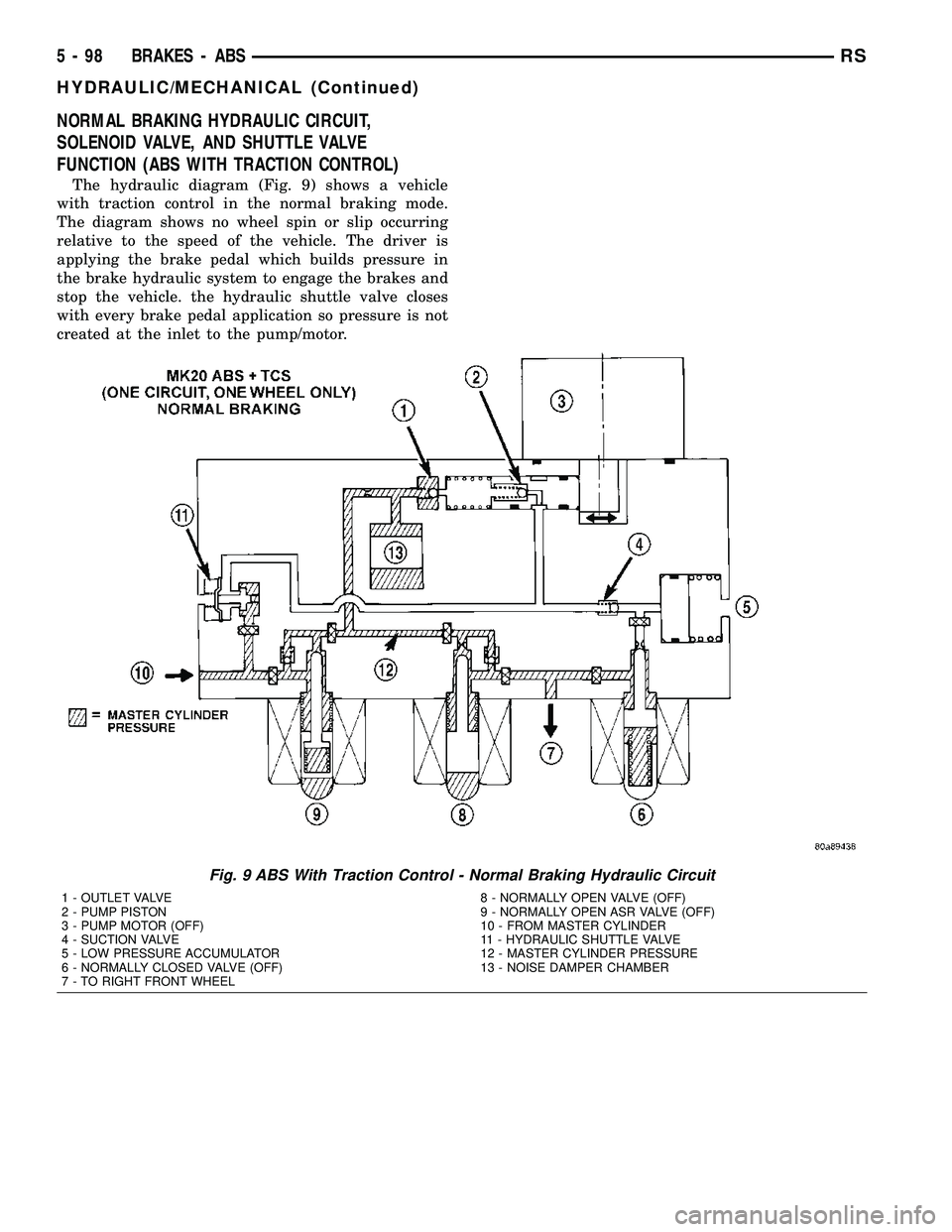
The hydraulic diagram (Fig. 9) shows a vehicle
with traction control in the normal braking mode.
The diagram shows no wheel spin or slip occurring
relative to the speed of the vehicle. The driver is
applying the brake pedal which builds pressure in
the brake hydraulic system to engage the brakes and
stop the vehicle. the hydraulic shuttle valve closes
with every brake pedal application so pressure is not
created at the inlet to the pump/motor.
Fig. 9 ABS With Traction Control - Normal Braking Hydraulic Circuit
1 - OUTLET VALVE
2 - PUMP PISTON
3 - PUMP MOTOR (OFF)
4 - SUCTION VALVE
5 - LOW PRESSURE ACCUMULATOR
6 - NORMALLY CLOSED VALVE (OFF)
7 - TO RIGHT FRONT WHEEL8 - NORMALLY OPEN VALVE (OFF)
9 - NORMALLY OPEN ASR VALVE (OFF)
10 - FROM MASTER CYLINDER
11 - HYDRAULIC SHUTTLE VALVE
12 - MASTER CYLINDER PRESSURE
13 - NOISE DAMPER CHAMBER
5 - 98 BRAKES - ABSRS
HYDRAULIC/MECHANICAL (Continued)
Page 210 of 2339

ABS BRAKING HYDRAULIC CIRCUIT, SOLENOID
VALVE, AND SHUTTLE VALVE FUNCTION (ABS
WITH TRACTION CONTROL)
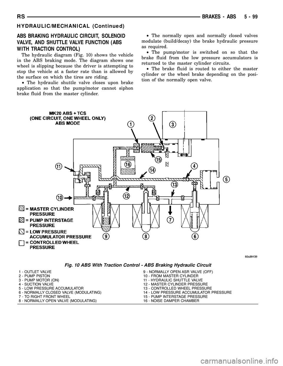
The hydraulic diagram (Fig. 10) shows the vehicle
in the ABS braking mode. The diagram shows one
wheel is slipping because the driver is attempting to
stop the vehicle at a faster rate than is allowed by
the surface on which the tires are riding.
²The hydraulic shuttle valve closes upon brake
application so that the pump/motor cannot siphon
brake fluid from the master cylinder.²The normally open and normally closed valves
modulate (build/decay) the brake hydraulic pressure
as required.
²The pump/motor is switched on so that the
brake fluid from the low pressure accumulators is
returned to the master cylinder circuits.
²The brake fluid is routed to either the master
cylinder or the wheel brake depending on the posi-
tion of the normally open valve.
Fig. 10 ABS With Traction Control - ABS Braking Hydraulic Circuit
1 - OUTLET VALVE
2 - PUMP PISTON
3 - PUMP MOTOR (ON)
4 - SUCTION VALVE
5 - LOW PRESSURE ACCUMULATOR
6 - NORMALLY CLOSED VALVE (MODULATING)
7 - TO RIGHT FRONT WHEEL
8 - NORMALLY OPEN VALVE (MODULATING)9 - NORMALLY OPEN ASR VALVE (OFF)
10 - FROM MASTER CYLINDER
11 - HYDRAULIC SHUTTLE VALVE
12 - MASTER CYLINDER PRESSURE
13 - CONTROLLED WHEEL PRESSURE
14 - LOW PRESSURE ACCUMULATOR PRESSURE
15 - PUMP INTERSTAGE PRESSURE
16 - NOISE DAMPER CHAMBER
RSBRAKES - ABS5-99
HYDRAULIC/MECHANICAL (Continued)
Page 211 of 2339

ABS TRACTION CONTROL HYDRAULIC CIRCUIT,
SOLENOID VALVE, AND SHUTTLE VALVE
FUNCTION (ABS WITH TRACTION CONTROL)
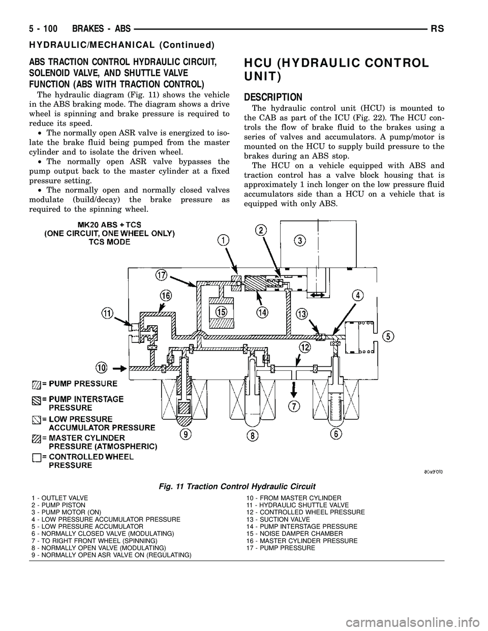
The hydraulic diagram (Fig. 11) shows the vehicle
in the ABS braking mode. The diagram shows a drive
wheel is spinning and brake pressure is required to
reduce its speed.
²The normally open ASR valve is energized to iso-
late the brake fluid being pumped from the master
cylinder and to isolate the driven wheel.
²The normally open ASR valve bypasses the
pump output back to the master cylinder at a fixed
pressure setting.
²The normally open and normally closed valves
modulate (build/decay) the brake pressure as
required to the spinning wheel.
HCU (HYDRAULIC CONTROL
UNIT)
DESCRIPTION
The hydraulic control unit (HCU) is mounted to
the CAB as part of the ICU (Fig. 22). The HCU con-
trols the flow of brake fluid to the brakes using a
series of valves and accumulators. A pump/motor is
mounted on the HCU to supply build pressure to the
brakes during an ABS stop.
The HCU on a vehicle equipped with ABS and
traction control has a valve block housing that is
approximately 1 inch longer on the low pressure fluid
accumulators side than a HCU on a vehicle that is
equipped with only ABS.
Fig. 11 Traction Control Hydraulic Circuit
1 - OUTLET VALVE
2 - PUMP PISTON
3 - PUMP MOTOR (ON)
4 - LOW PRESSURE ACCUMULATOR PRESSURE
5 - LOW PRESSURE ACCUMULATOR
6 - NORMALLY CLOSED VALVE (MODULATING)
7 - TO RIGHT FRONT WHEEL (SPINNING)
8 - NORMALLY OPEN VALVE (MODULATING)
9 - NORMALLY OPEN ASR VALVE ON (REGULATING)10 - FROM MASTER CYLINDER
11 - HYDRAULIC SHUTTLE VALVE
12 - CONTROLLED WHEEL PRESSURE
13 - SUCTION VALVE
14 - PUMP INTERSTAGE PRESSURE
15 - NOISE DAMPER CHAMBER
16 - MASTER CYLINDER PRESSURE
17 - PUMP PRESSURE
5 - 100 BRAKES - ABSRS
HYDRAULIC/MECHANICAL (Continued)
Page 250 of 2339

(5) Install the upper radiator mounts to the cross-
member bolts, if removed. Tighten to 8 N´m (70 in.
lbs.).
(6) Install the radiator upper hose to the support
clip (2.4L engine).
RADIATOR FAN RELAY
DESCRIPTION
The radiator fan relay is a solid state type and is
located on the front bumper reinforcment (Fig. 21).
Refer to WIRING DIAGRAMS for a circuit sche-
matic.
OPERATION
The solid state radiator fan relay is controlled by
the Powertrain Control Module (PCM) by way of a
Pulse Width Modulated (PWM) signal. The relay con-
trol circuit supplies a 12 volt signal to the PCM. The
PCM then pulses the ground circuit to achieve fan on
time. The relay provides a voltage to the fan motors
which is proportional to the pulse width it receives
from the PCM. The duty cycle ranges from 30% for
low speed operation, then ramps-up to 100% for high
speed operation. This fan control system provides
infinitely variable fan speeds, allowing for improved
fan noise, A/C performance, better engine cooling,
and additional vehicle power.
To control operation of the relay, the PCM looks at
inputs from:
²Engine coolant temperature
²A/C pressure transducer
²Ambient temperature from the body controller
²Vehicle speed
²Transmission oil temperature
The PCM uses these inputs to determine when the
fan should operate and at what speed. For further
information on fan operation, (Refer to 7 - COOL-
ING/ENGINE/RADIATOR FAN - OPERATION).
REMOVAL
(1) Open hood.
(2) Disconnect and isolate the battery negative
cable.
(3) Remove the radiator crossmember to front fas-
cia closure panel.
(4) Disconnect the relay electrical connector (Fig.
21).
(5) Remove the rivet attaching the relay to the
front bumper beam (Fig. 21).
(6) Remove the relay.
INSTALLATION
CAUTION: The relay mounting location is designed
to dissipate heat. Ensure the relay is securely
attached to prevent relay ªthermalº shutdown and
relay damage, resulting in possible engine over-
heating.
(1) Position relay and install a new rivet (Fig. 21).
(2) Connect electrical connector to relay.
(3) Install closure panel and attaching screws.
(4) Connect negative cable to battery.
Fig. 21 Radiator Fan Relay
1 - FRONT FASCIA
2 - FAN RELAY
3 - RIVET
4 - A/C CONDENSER (FRONT SIDE)
RSENGINE7-31
RADIATOR FAN (Continued)
Page 272 of 2339

(6) Install glove box (Refer to 23 - BODY/INSTRU-
MENT PANEL/GLOVE BOX - INSTALLATION).
(7) Connect the battery negative cable.
QUARTER GLASS INTEGRAL
ANTENNA - EXPORT
DESCRIPTION
The quarter glass integral antenna element is
bonded to the right rear quarter glass and is replaced
with the glass assembly only (Fig. 12).
OPERATION
The integral antenna receives radio frequencies
and sends them to the antenna module for amplifica-
tion.
DIAGNOSIS AND TESTING
QUARTER GLASS INTEGRAL ANTENNA -
EXPORT
The antenna grid pattern is divided into two sepa-
rate patterns. Each terminal connects to a separate
grid pattern, one for AM and the other for FM.
For circuit descriptions and diagrams, refer to the
appropriate wiring information.
(1) Disconnect the antenna module connector from
the antenna terminals on the glass.
(2) Using an ohmmeter, place a lead on one of the
terminals and check each end of the grid pattern con-
nected to this terminal for continuity. If continuity is
not present, move one lead through the grid in pro-
gression starting at the terminal with the other lead
on the terminal until continuity is lost. Repeat pro-
cedure for the other terminal. A break in the antenna
grid can be repaired using a Mopar Rear Window
Defogger Repair Kit (Part Number 4267922) or
equivalent. (Refer to 8 - ELECTRICAL/HEATED
GLASS/WINDSHIELD GRID - STANDARD PROCE-
DURE).
RADIO
DESCRIPTION
Available radio receivers for this vehicle include:
²AM/FM/cassette/CD (RAZ or RBP sales code)
²AM/FM/cassette/CD with rear audio (RBU sales
code)
²AM/FM/cassette (RBB sales code)
²AM/FM/6±disc CD radio (RBQ sales code)
²AM/FM/CD/Navigation (RB3 sales code)
²AM/FM/CD with CD changer control (RBK sales
code) export only
²AM/FM/cassette/CD (RBY,RAD, or RBT sales
code) export only
All radio receivers can communicate on the Pro-
grammable Communications Interface (PCI) data bus
network.
Fig. 11 ANTENNA TO RADIO
1 - RADIO
2 - LOCKING ANTENNA CONNECTOR
3 - INSTRUMENT PANEL ANTENNA CABLE
Fig. 12 QUARTER GLASS INTEGRAL ANTENNA
1 - REAR QUARTER GLASS
2 - ANTENNA
RSAUDIO/VIDEO8A-13
INSTRUMENT PANEL ANTENNA CABLE (Continued)