2005 CHRYSLER VOYAGER roof
[x] Cancel search: roofPage 1819 of 2339
DECKLID/HATCH/LIFTGATE/TAILGATE
TABLE OF CONTENTS
page page
EXTERIOR HANDLE
REMOVAL.............................40
INSTALLATION.........................40
HINGE
REMOVAL.............................40
INSTALLATION.........................40
LATCH
REMOVAL.............................41
INSTALLATION.........................41
LATCH STRIKER
REMOVAL.............................41
INSTALLATION.........................42
LIFTGATE
REMOVAL.............................42
INSTALLATION.........................42
LOCK CYLINDER
REMOVAL.............................42INSTALLATION.........................42
SUPPORT CYLINDER
REMOVAL.............................42
INSTALLATION.........................43
TRIM PANEL
REMOVAL.............................43
INSTALLATION.........................43
SLAM BUMPER
REMOVAL
REMOVAL - BODY SIDE................44
REMOVAL - LIFTGATE SIDE.............44
INSTALLATION
INSTALLATION - BODY SIDE............44
INSTALLATION - LIFTGATE SIDE.........44
EXTERIOR HANDLE
REMOVAL
(1) Remove liftgate trim panel. (Refer to 23 -
BODY/DECKLID/HATCH/LIFTGATE/TAILGATE/
TRIM PANEL - REMOVAL)
(2) Disconnect the exterior handle electrical con-
nectors.
(3) Remove the two outer screws and the two inner
screws.
(4) Remove the exterior handle/license plate light
assembly.
INSTALLATION
(1) Route the exterior handle electrical connector
through the door and position handle.
(2) Install the two out screws and tighten to 3 N´m
(22 in. lbs.).
(3) Install the two inner bolts and tighten to 5
N´m (40 in. lbs.).
(4) Connect the electrical connector.
(5) Install the trim panel. (Refer to 23 - BODY/
DECKLID/HATCH/LIFTGATE/TAILGATE/TRIM
PANEL - INSTALLATION)
HINGE
REMOVAL
(1) Release liftgate latch and open liftgate.
(2) Support liftgate on a suitable lifting device in
the full open position.
(3) Apply several layers of duct tape on the outside
of to roof across the gap to the lift gate to hold the
liftgate in position.
(4) Remove bolts attaching liftgate hinge to roof
header.
(5) Disconnect VTSS switch from the body har-
ness.
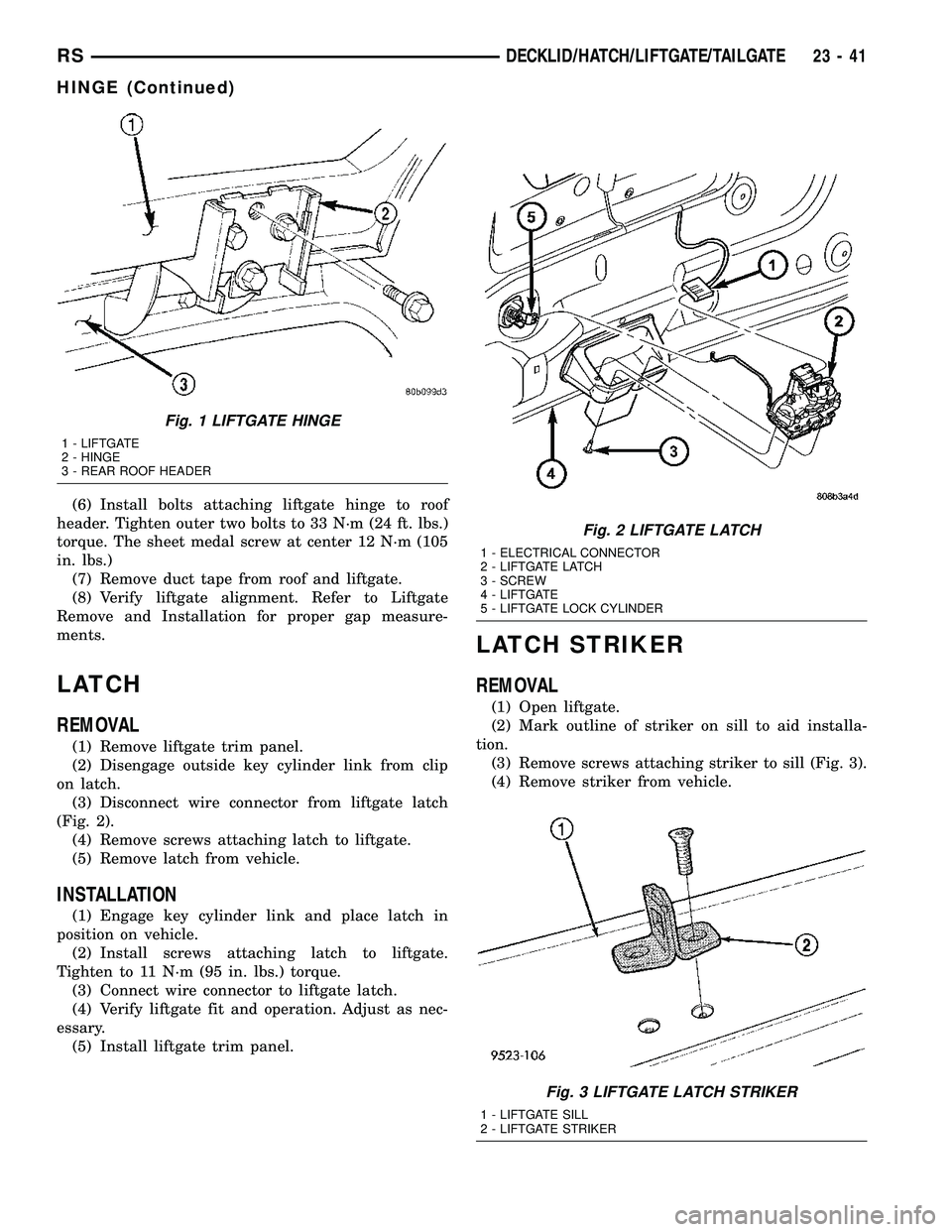
(6) Remove bolts attaching hinge to liftgate (Fig.
1).
(7) Remove hinge from vehicle.
INSTALLATION
(1) If necessary, paint replacement hinge before
installation.
(2) Place hinge in position on vehicle.
(3) Align hinge to marks on liftgate.
(4) Install bolts attaching hinge to liftgate (Fig. 1).
Tighten bolts to 33 N´m (24 ft. lbs.) torque.
(5) Align hinge to marks on roof header.
23 - 40 DECKLID/HATCH/LIFTGATE/TAILGATERS
Page 1820 of 2339
(6) Install bolts attaching liftgate hinge to roof
header. Tighten outer two bolts to 33 N´m (24 ft. lbs.)
torque. The sheet medal screw at center 12 N´m (105
in. lbs.)
(7) Remove duct tape from roof and liftgate.
(8) Verify liftgate alignment. Refer to Liftgate
Remove and Installation for proper gap measure-
ments.
LATCH
REMOVAL
(1) Remove liftgate trim panel.
(2) Disengage outside key cylinder link from clip
on latch.
(3) Disconnect wire connector from liftgate latch
(Fig. 2).
(4) Remove screws attaching latch to liftgate.
(5) Remove latch from vehicle.
INSTALLATION
(1) Engage key cylinder link and place latch in
position on vehicle.
(2) Install screws attaching latch to liftgate.
Tighten to 11 N´m (95 in. lbs.) torque.
(3) Connect wire connector to liftgate latch.
(4) Verify liftgate fit and operation. Adjust as nec-
essary.
(5) Install liftgate trim panel.
LATCH STRIKER
REMOVAL
(1) Open liftgate.
(2) Mark outline of striker on sill to aid installa-
tion.
(3) Remove screws attaching striker to sill (Fig. 3).
(4) Remove striker from vehicle.
Fig. 1 LIFTGATE HINGE
1 - LIFTGATE
2 - HINGE
3 - REAR ROOF HEADER
Fig. 2 LIFTGATE LATCH
1 - ELECTRICAL CONNECTOR
2 - LIFTGATE LATCH
3 - SCREW
4 - LIFTGATE
5 - LIFTGATE LOCK CYLINDER
Fig. 3 LIFTGATE LATCH STRIKER
1 - LIFTGATE SILL
2 - LIFTGATE STRIKER
RSDECKLID/HATCH/LIFTGATE/TAILGATE23-41
HINGE (Continued)
Page 1821 of 2339
INSTALLATION
(1) Place striker in position on vehicle.
(2) Align striker to outline mark on sill.
(3) Install screws attaching striker to sill. Tighten
screws to 28 N´m (21 ft. lbs.) torque.
(4) Verify liftgate alignment and operation.
LIFTGATE
REMOVAL
(1) Disconnect and isolate the battery negative
cable.
(2) Release liftgate latch and open liftgate.
(3) Remove liftgate upper frame molding.
(4) Remove screws attaching liftgate wire connec-
tor to rear header.
(5) Disconnect liftgate wire harness from body
wire harness.
(6) Disconnect rear window washer hose from
spray nozzle.
(7) Support liftgate on a suitable lifting device.
(8) Disconnect power liftgate link, if equipped.
(9) Remove screws attaching support cylinders to
liftgate.
(10) Remove bolts attaching liftgate hinge to roof
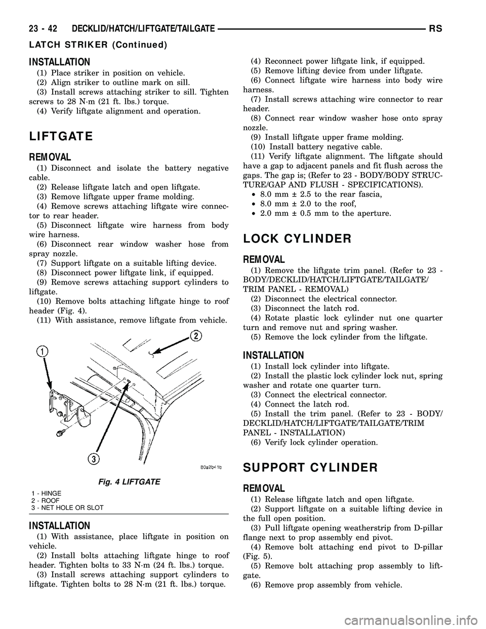
header (Fig. 4).
(11) With assistance, remove liftgate from vehicle.
INSTALLATION
(1) With assistance, place liftgate in position on
vehicle.
(2) Install bolts attaching liftgate hinge to roof
header. Tighten bolts to 33 N´m (24 ft. lbs.) torque.
(3) Install screws attaching support cylinders to
liftgate. Tighten bolts to 28 N´m (21 ft. lbs.) torque.(4) Reconnect power liftgate link, if equipped.
(5) Remove lifting device from under liftgate.
(6) Connect liftgate wire harness into body wire
harness.
(7) Install screws attaching wire connector to rear
header.
(8) Connect rear window washer hose onto spray
nozzle.
(9) Install liftgate upper frame molding.
(10) Install battery negative cable.
(11) Verify liftgate alignment. The liftgate should
have a gap to adjacent panels and fit flush across the
gaps. The gap is; (Refer to 23 - BODY/BODY STRUC-
TURE/GAP AND FLUSH - SPECIFICATIONS).
²8.0 mm 2.5 to the rear fascia,
²8.0 mm 2.0 to the roof,
²2.0 mm 0.5 mm to the aperture.
LOCK CYLINDER
REMOVAL
(1) Remove the liftgate trim panel. (Refer to 23 -
BODY/DECKLID/HATCH/LIFTGATE/TAILGATE/
TRIM PANEL - REMOVAL)
(2) Disconnect the electrical connector.
(3) Disconnect the latch rod.
(4) Rotate plastic lock cylinder nut one quarter
turn and remove nut and spring washer.
(5) Remove the lock cylinder from the liftgate.
INSTALLATION
(1) Install lock cylinder into liftgate.
(2) Install the plastic lock cylinder lock nut, spring
washer and rotate one quarter turn.
(3) Connect the electrical connector.
(4) Connect the latch rod.
(5) Install the trim panel. (Refer to 23 - BODY/
DECKLID/HATCH/LIFTGATE/TAILGATE/TRIM
PANEL - INSTALLATION)
(6) Verify lock cylinder operation.
SUPPORT CYLINDER
REMOVAL
(1) Release liftgate latch and open liftgate.
(2) Support liftgate on a suitable lifting device in
the full open position.
(3) Pull liftgate opening weatherstrip from D-pillar
flange next to prop assembly end pivot.
(4) Remove bolt attaching end pivot to D-pillar
(Fig. 5).
(5) Remove bolt attaching prop assembly to lift-
gate.
(6) Remove prop assembly from vehicle.
Fig. 4 LIFTGATE
1 - HINGE
2 - ROOF
3 - NET HOLE OR SLOT
23 - 42 DECKLID/HATCH/LIFTGATE/TAILGATERS
LATCH STRIKER (Continued)
Page 1824 of 2339
EXTERIOR
TABLE OF CONTENTS
page page
BODY SIDE MOLDINGS
REMOVAL.............................45
INSTALLATION.........................46
COWL GRILLE
REMOVAL.............................50
INSTALLATION.........................50
EXTERIOR NAME PLATES - TAPE ATTACHED
REMOVAL.............................51
INSTALLATION.........................51
EXTERIOR NAME PLATES - ADHESIVE
ATTACHED
REMOVAL.............................51
INSTALLATION.........................51
FRONT FENDER
REMOVAL.............................51
INSTALLATION.........................52
FUEL FILL DOOR
REMOVAL.............................52
INSTALLATION.........................52
FUEL FILL DOOR BLOCKER LATCH
REMOVAL.............................53
INSTALLATION.........................53
FUEL FILL DOOR BLOCKER LATCH STRIKER
REMOVAL.............................53
INSTALLATION.........................53
FUEL FILL DOOR BLOCKER LOCKOUT LINK
REMOVAL.............................54
INSTALLATION.........................54
GRILLE
DESCRIPTION.........................55REMOVAL.............................55
INSTALLATION.........................55
UPPER RADIATOR CROSSMEMBER
REMOVAL.............................56
INSTALLATION.........................56
FRONT WHEELHOUSE SPLASH SHIELD
REMOVAL.............................57
INSTALLATION.........................57
LUGGAGE RACK RISER
REMOVAL.............................57
INSTALLATION.........................58
LUGGAGE RACK CROSSBAR
REMOVAL.............................58
INSTALLATION.........................59
REAR QUARTER PANEL/FENDER AIR
EXHAUSTER
DESCRIPTION.........................59
REMOVAL.............................59
INSTALLATION.........................60
ROOF JOINT MOLDING
REMOVAL.............................60
INSTALLATION.........................60
SIDE VIEW MIRROR
REMOVAL.............................60
INSTALLATION.........................60
GLASS-OUTSIDE REARVIEW MIRROR
REMOVAL.............................61
INSTALLATION.........................61
BODY SIDE MOLDINGS
REMOVAL
Refer to (Fig. 1), (Fig. 2), (Fig. 3), (Fig. 4) or (Fig.
5)for proper location of fasteners holding the molding
to the wheelhouse lip and rocker panels.
(1) Warm the affected stick on molding and body
metal to approximately 38É C (100É F) using a suit-
able heat lamp or heat gun.(2) If equipped, remove pop rivets holding molding
edge to wheelhouse lip.
(3) Pull stick on molding from painted surface.
(4) Remove adhesive tape residue from painted
surface of vehicle. Use a 3M Scotch-BriteŸ Molding
Adhesive and Stripe Removal Disc, or equivalent, to
clean adhesive residue from painted surfaces. These
products are available from automotive paint suppli-
ers. Refer to instructions supplied with the specific
product for proper usage.
RSEXTERIOR23-45
Page 1839 of 2339
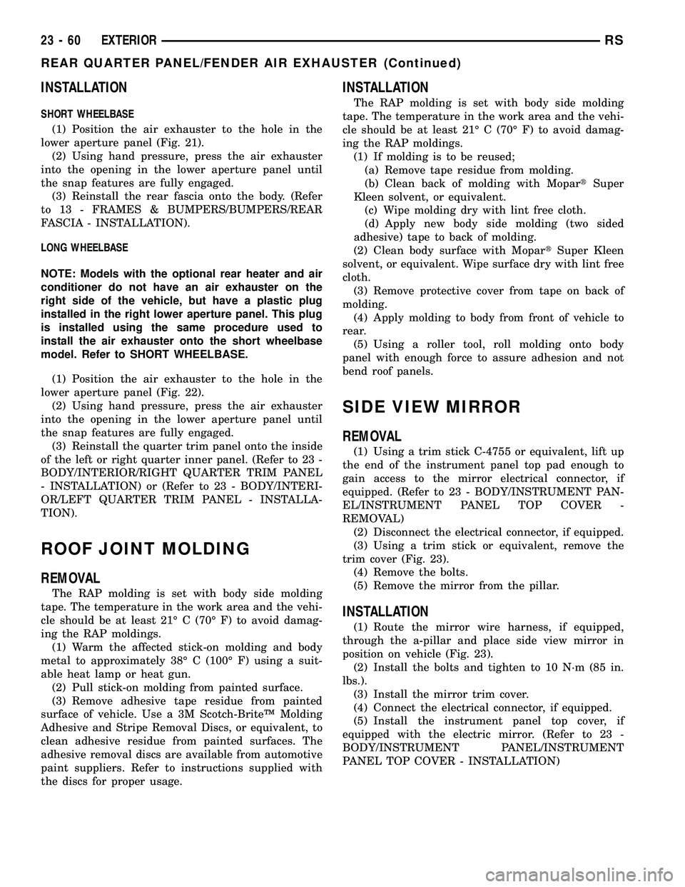
INSTALLATION
SHORT WHEELBASE
(1) Position the air exhauster to the hole in the
lower aperture panel (Fig. 21).
(2) Using hand pressure, press the air exhauster
into the opening in the lower aperture panel until
the snap features are fully engaged.
(3) Reinstall the rear fascia onto the body. (Refer
to 13 - FRAMES & BUMPERS/BUMPERS/REAR
FASCIA - INSTALLATION).
LONG WHEELBASE
NOTE: Models with the optional rear heater and air
conditioner do not have an air exhauster on the
right side of the vehicle, but have a plastic plug
installed in the right lower aperture panel. This plug
is installed using the same procedure used to
install the air exhauster onto the short wheelbase
model. Refer to SHORT WHEELBASE.
(1) Position the air exhauster to the hole in the
lower aperture panel (Fig. 22).
(2) Using hand pressure, press the air exhauster
into the opening in the lower aperture panel until
the snap features are fully engaged.
(3) Reinstall the quarter trim panel onto the inside
of the left or right quarter inner panel. (Refer to 23 -
BODY/INTERIOR/RIGHT QUARTER TRIM PANEL
- INSTALLATION) or (Refer to 23 - BODY/INTERI-
OR/LEFT QUARTER TRIM PANEL - INSTALLA-
TION).
ROOF JOINT MOLDING
REMOVAL
The RAP molding is set with body side molding
tape. The temperature in the work area and the vehi-
cle should be at least 21É C (70É F) to avoid damag-
ing the RAP moldings.
(1) Warm the affected stick-on molding and body
metal to approximately 38É C (100É F) using a suit-
able heat lamp or heat gun.
(2) Pull stick-on molding from painted surface.
(3) Remove adhesive tape residue from painted
surface of vehicle. Use a 3M Scotch-BriteŸ Molding
Adhesive and Stripe Removal Discs, or equivalent, to
clean adhesive residue from painted surfaces. The
adhesive removal discs are available from automotive
paint suppliers. Refer to instructions supplied with
the discs for proper usage.
INSTALLATION
The RAP molding is set with body side molding
tape. The temperature in the work area and the vehi-
cle should be at least 21É C (70É F) to avoid damag-
ing the RAP moldings.
(1) If molding is to be reused;
(a) Remove tape residue from molding.
(b) Clean back of molding with MopartSuper
Kleen solvent, or equivalent.
(c) Wipe molding dry with lint free cloth.
(d) Apply new body side molding (two sided
adhesive) tape to back of molding.
(2) Clean body surface with MopartSuper Kleen
solvent, or equivalent. Wipe surface dry with lint free
cloth.
(3) Remove protective cover from tape on back of
molding.
(4) Apply molding to body from front of vehicle to
rear.
(5) Using a roller tool, roll molding onto body
panel with enough force to assure adhesion and not
bend roof panels.
SIDE VIEW MIRROR
REMOVAL
(1) Using a trim stick C-4755 or equivalent, lift up
the end of the instrument panel top pad enough to
gain access to the mirror electrical connector, if
equipped. (Refer to 23 - BODY/INSTRUMENT PAN-
EL/INSTRUMENT PANEL TOP COVER -
REMOVAL)
(2) Disconnect the electrical connector, if equipped.
(3) Using a trim stick or equivalent, remove the
trim cover (Fig. 23).
(4) Remove the bolts.
(5) Remove the mirror from the pillar.
INSTALLATION
(1) Route the mirror wire harness, if equipped,
through the a-pillar and place side view mirror in
position on vehicle (Fig. 23).
(2) Install the bolts and tighten to 10 N´m (85 in.
lbs.).
(3) Install the mirror trim cover.
(4) Connect the electrical connector, if equipped.
(5) Install the instrument panel top cover, if
equipped with the electric mirror. (Refer to 23 -
BODY/INSTRUMENT PANEL/INSTRUMENT
PANEL TOP COVER - INSTALLATION)
23 - 60 EXTERIORRS
REAR QUARTER PANEL/FENDER AIR EXHAUSTER (Continued)
Page 1858 of 2339
A-PILLAR LOWER EXTENSION
TRIM
REMOVAL
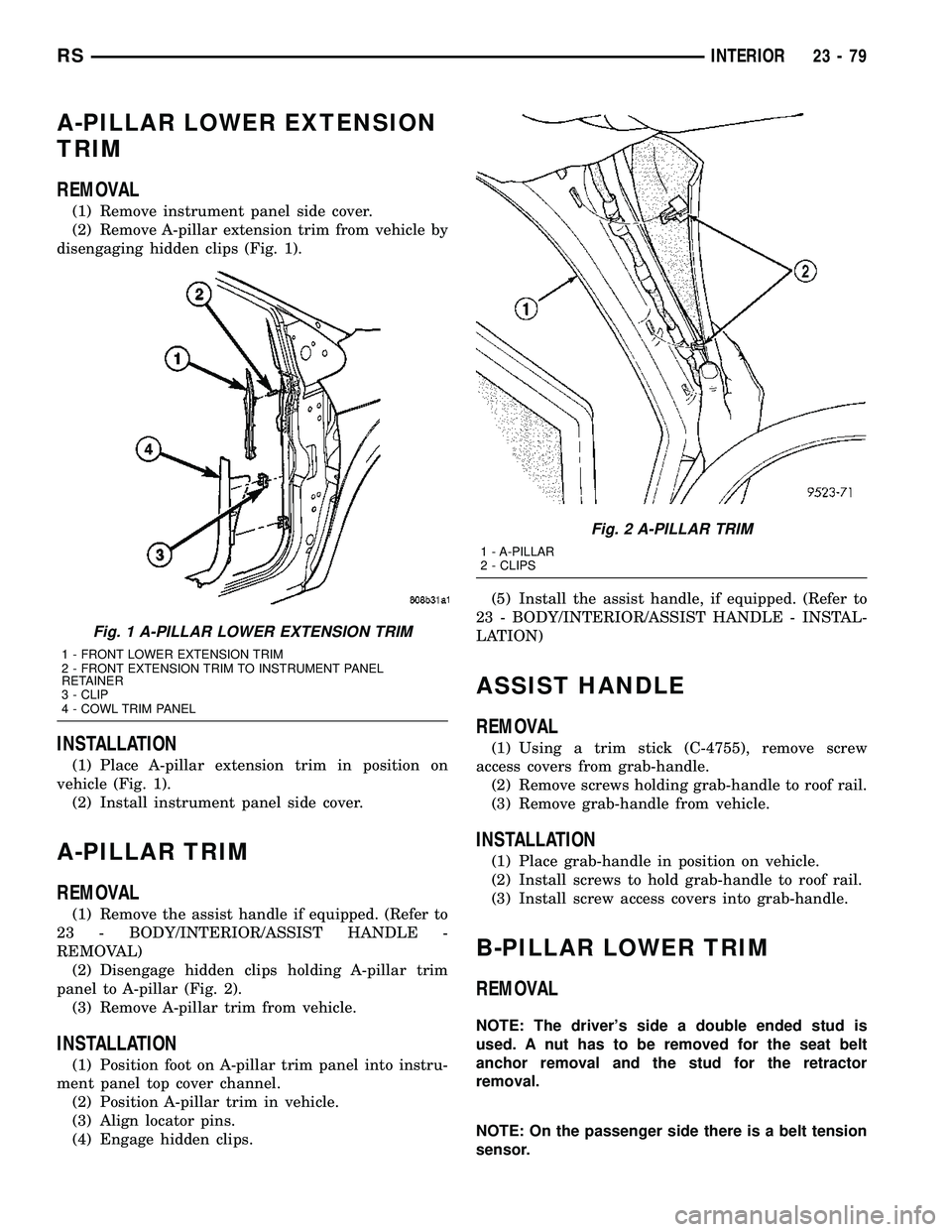
(1) Remove instrument panel side cover.
(2) Remove A-pillar extension trim from vehicle by
disengaging hidden clips (Fig. 1).
INSTALLATION
(1) Place A-pillar extension trim in position on
vehicle (Fig. 1).
(2) Install instrument panel side cover.
A-PILLAR TRIM
REMOVAL
(1) Remove the assist handle if equipped. (Refer to
23 - BODY/INTERIOR/ASSIST HANDLE -
REMOVAL)
(2) Disengage hidden clips holding A-pillar trim
panel to A-pillar (Fig. 2).
(3) Remove A-pillar trim from vehicle.
INSTALLATION
(1) Position foot on A-pillar trim panel into instru-
ment panel top cover channel.
(2) Position A-pillar trim in vehicle.
(3) Align locator pins.
(4) Engage hidden clips.(5) Install the assist handle, if equipped. (Refer to
23 - BODY/INTERIOR/ASSIST HANDLE - INSTAL-
LATION)
ASSIST HANDLE
REMOVAL
(1) Using a trim stick (C-4755), remove screw
access covers from grab-handle.
(2) Remove screws holding grab-handle to roof rail.
(3) Remove grab-handle from vehicle.
INSTALLATION
(1) Place grab-handle in position on vehicle.
(2) Install screws to hold grab-handle to roof rail.
(3) Install screw access covers into grab-handle.
B-PILLAR LOWER TRIM
REMOVAL
NOTE: The driver's side a double ended stud is
used. A nut has to be removed for the seat belt
anchor removal and the stud for the retractor
removal.
NOTE: On the passenger side there is a belt tension
sensor.
Fig. 1 A-PILLAR LOWER EXTENSION TRIM
1 - FRONT LOWER EXTENSION TRIM
2 - FRONT EXTENSION TRIM TO INSTRUMENT PANEL
RETAINER
3 - CLIP
4 - COWL TRIM PANEL
Fig. 2 A-PILLAR TRIM
1 - A-PILLAR
2 - CLIPS
RSINTERIOR23-79
Page 1870 of 2339
HEADLINER
REMOVAL
(1) Remove sun visors and vanity mirrors.
(2) Remove sun visor center supports.
(3) If equipped, remove coat hooks.
(4) If equipped, remove roof rail modules.
(5) Remove A-pillar trim covers. (Refer to 23 -
BODY/INTERIOR/A-PILLAR TRIM - REMOVAL).
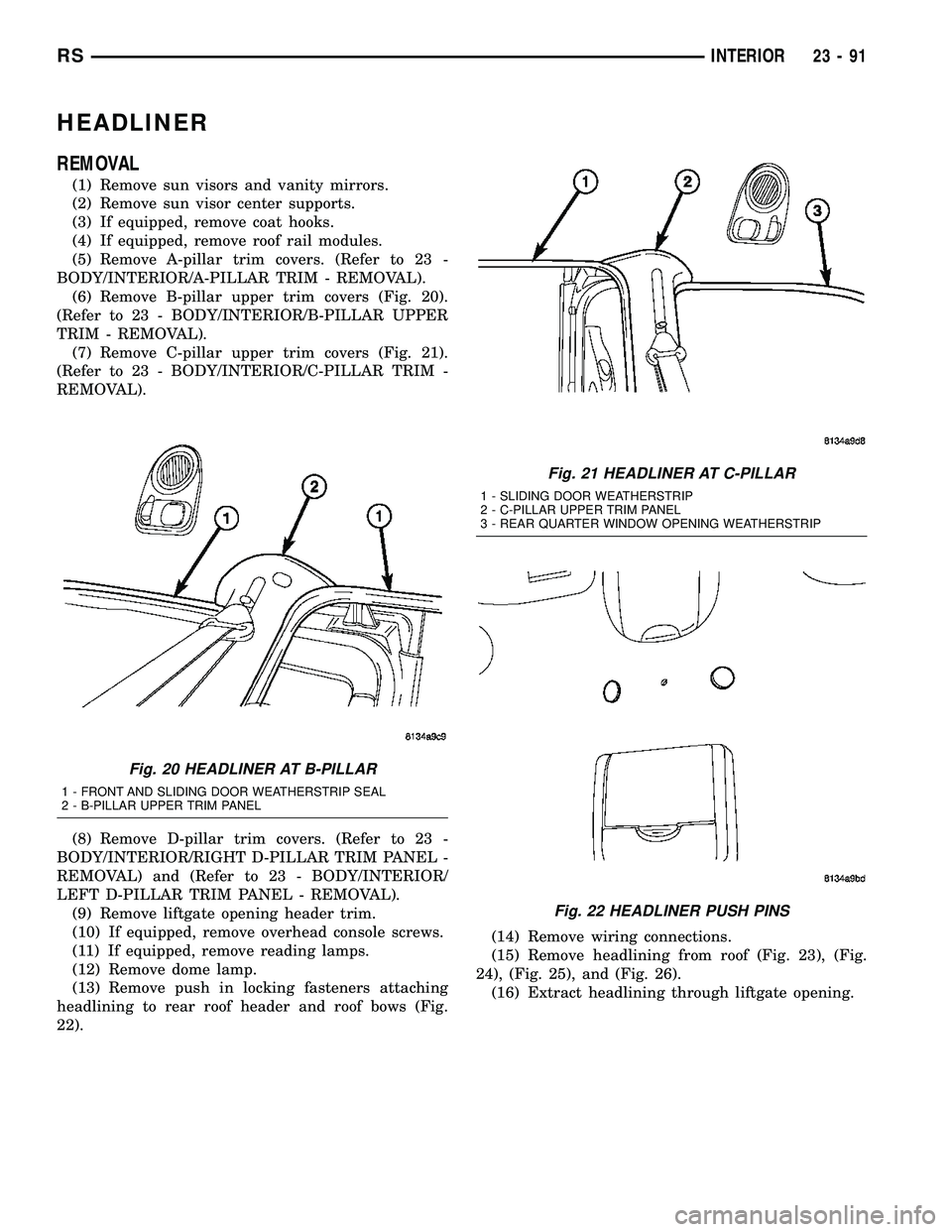
(6) Remove B-pillar upper trim covers (Fig. 20).
(Refer to 23 - BODY/INTERIOR/B-PILLAR UPPER
TRIM - REMOVAL).
(7) Remove C-pillar upper trim covers (Fig. 21).
(Refer to 23 - BODY/INTERIOR/C-PILLAR TRIM -
REMOVAL).
(8) Remove D-pillar trim covers. (Refer to 23 -
BODY/INTERIOR/RIGHT D-PILLAR TRIM PANEL -
REMOVAL) and (Refer to 23 - BODY/INTERIOR/
LEFT D-PILLAR TRIM PANEL - REMOVAL).
(9) Remove liftgate opening header trim.
(10) If equipped, remove overhead console screws.
(11) If equipped, remove reading lamps.
(12) Remove dome lamp.
(13) Remove push in locking fasteners attaching
headlining to rear roof header and roof bows (Fig.
22).(14) Remove wiring connections.
(15) Remove headlining from roof (Fig. 23), (Fig.
24), (Fig. 25), and (Fig. 26).
(16) Extract headlining through liftgate opening.
Fig. 20 HEADLINER AT B-PILLAR
1 - FRONT AND SLIDING DOOR WEATHERSTRIP SEAL
2 - B-PILLAR UPPER TRIM PANEL
Fig. 21 HEADLINER AT C-PILLAR
1 - SLIDING DOOR WEATHERSTRIP
2 - C-PILLAR UPPER TRIM PANEL
3 - REAR QUARTER WINDOW OPENING WEATHERSTRIP
Fig. 22 HEADLINER PUSH PINS
RSINTERIOR23-91
Page 1871 of 2339
INSTALLATION
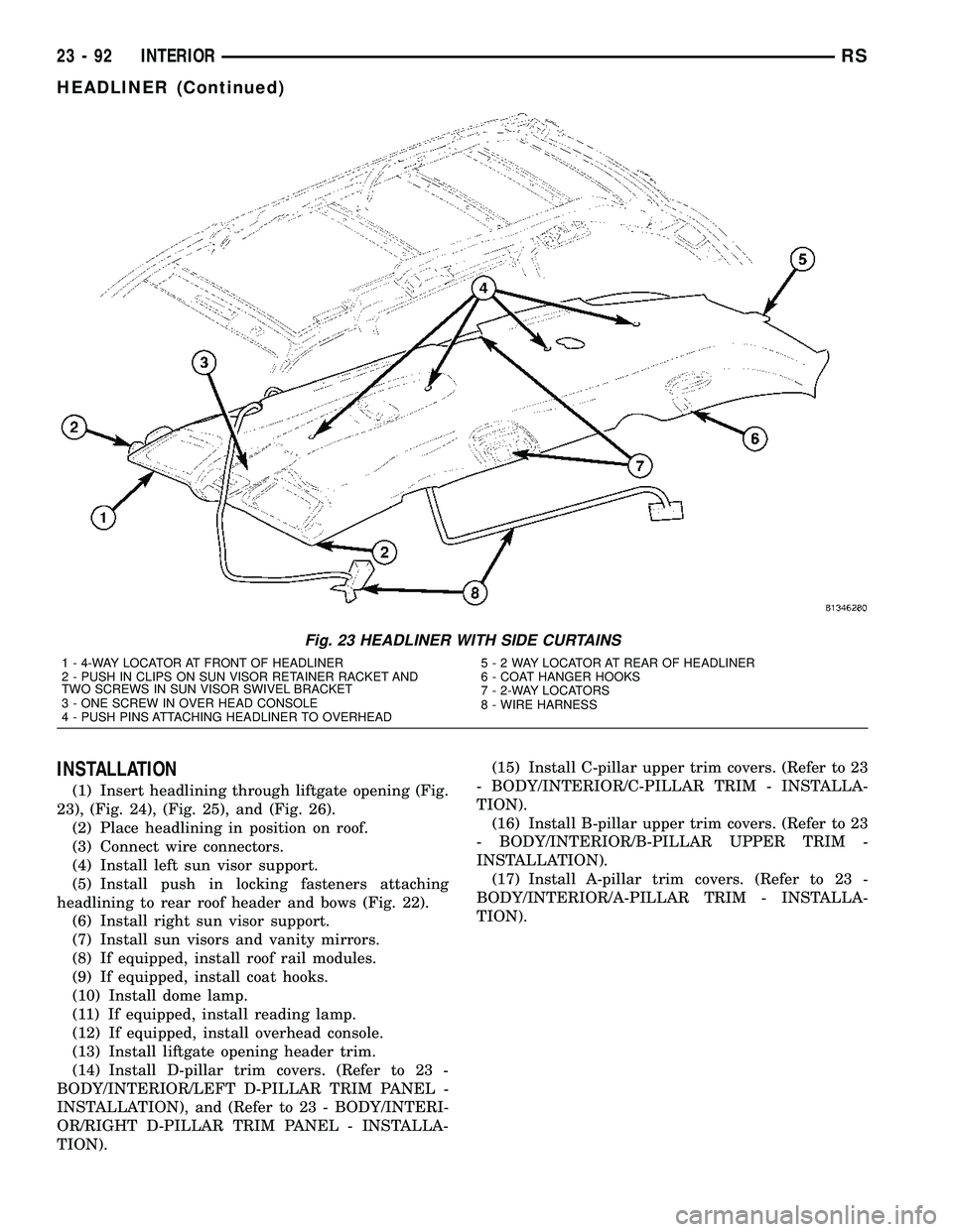
(1) Insert headlining through liftgate opening (Fig.
23), (Fig. 24), (Fig. 25), and (Fig. 26).
(2) Place headlining in position on roof.
(3) Connect wire connectors.
(4) Install left sun visor support.
(5) Install push in locking fasteners attaching
headlining to rear roof header and bows (Fig. 22).
(6) Install right sun visor support.
(7) Install sun visors and vanity mirrors.
(8) If equipped, install roof rail modules.
(9) If equipped, install coat hooks.
(10) Install dome lamp.
(11) If equipped, install reading lamp.
(12) If equipped, install overhead console.
(13) Install liftgate opening header trim.
(14) Install D-pillar trim covers. (Refer to 23 -
BODY/INTERIOR/LEFT D-PILLAR TRIM PANEL -
INSTALLATION), and (Refer to 23 - BODY/INTERI-
OR/RIGHT D-PILLAR TRIM PANEL - INSTALLA-
TION).(15) Install C-pillar upper trim covers. (Refer to 23
- BODY/INTERIOR/C-PILLAR TRIM - INSTALLA-
TION).
(16) Install B-pillar upper trim covers. (Refer to 23
- BODY/INTERIOR/B-PILLAR UPPER TRIM -
INSTALLATION).
(17) Install A-pillar trim covers. (Refer to 23 -
BODY/INTERIOR/A-PILLAR TRIM - INSTALLA-
TION).
Fig. 23 HEADLINER WITH SIDE CURTAINS
1 - 4-WAY LOCATOR AT FRONT OF HEADLINER
2 - PUSH IN CLIPS ON SUN VISOR RETAINER RACKET AND
TWO SCREWS IN SUN VISOR SWIVEL BRACKET
3 - ONE SCREW IN OVER HEAD CONSOLE
4 - PUSH PINS ATTACHING HEADLINER TO OVERHEAD5-2WAYLOCATOR AT REAR OF HEADLINER
6 - COAT HANGER HOOKS
7 - 2-WAY LOCATORS
8 - WIRE HARNESS
23 - 92 INTERIORRS
HEADLINER (Continued)