2005 CHRYSLER VOYAGER roof
[x] Cancel search: roofPage 1872 of 2339
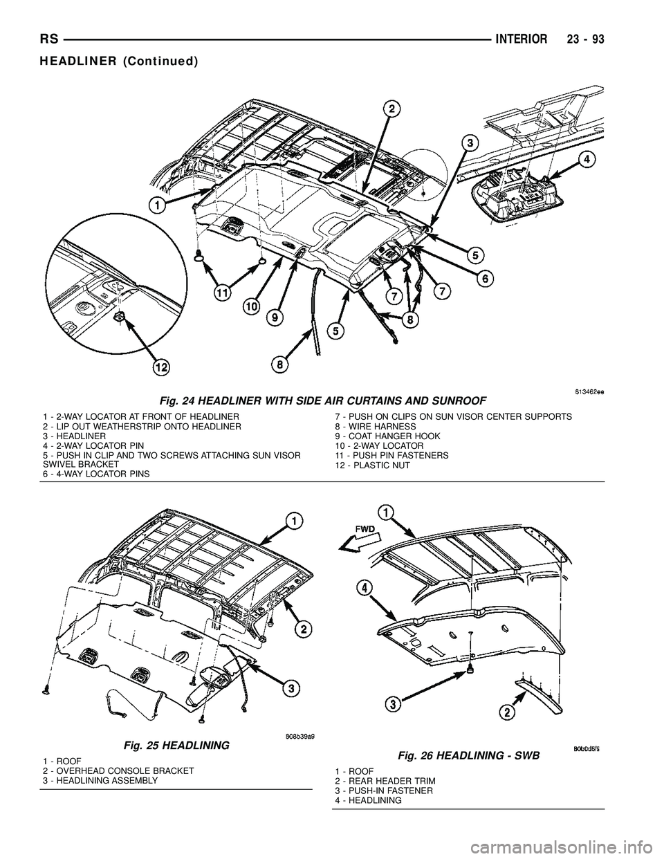
Fig. 24 HEADLINER WITH SIDE AIR CURTAINS AND SUNROOF
1 - 2-WAY LOCATOR AT FRONT OF HEADLINER
2 - LIP OUT WEATHERSTRIP ONTO HEADLINER
3 - HEADLINER
4 - 2-WAY LOCATOR PIN
5 - PUSH IN CLIP AND TWO SCREWS ATTACHING SUN VISOR
SWIVEL BRACKET
6 - 4-WAY LOCATOR PINS7 - PUSH ON CLIPS ON SUN VISOR CENTER SUPPORTS
8 - WIRE HARNESS
9 - COAT HANGER HOOK
10 - 2-WAY LOCATOR
11 - PUSH PIN FASTENERS
12 - PLASTIC NUT
Fig. 25 HEADLINING
1 - ROOF
2 - OVERHEAD CONSOLE BRACKET
3 - HEADLINING ASSEMBLYFig. 26 HEADLINING - SWB
1 - ROOF
2 - REAR HEADER TRIM
3 - PUSH-IN FASTENER
4 - HEADLINING
RSINTERIOR23-93
HEADLINER (Continued)
Page 1878 of 2339
INSTALLATION
(1) Place sill plate in position on vehicle.
(2) Engage hooks to hold outside edge of sill plate
to door sill.
(3) Align guide pins to holes in door sill.
(4) Engage hidden clips to hold sill plate to sliding
door opening sill.
(5) Engage interlock tabs at lower B-pillar and
quarter trim panel.
SUN VISOR
REMOVAL
All vehicles with driver and passenger side air
bags must have a colored coded five Bullet point air
bag warning label applied to the sun visor, verify
label availability and ensure the label is installed.
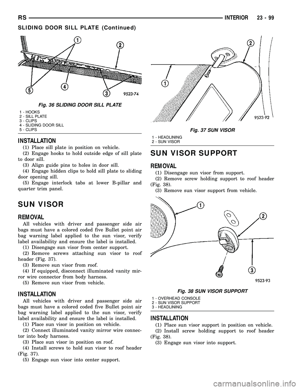
(1) Disengage sun visor from center support.
(2) Remove screws attaching sun visor to roof
header (Fig. 37).
(3) Remove sun visor from roof.
(4) If equipped, disconnect illuminated vanity mir-
ror wire connector from body harness.
(5) Remove sun visor from vehicle.
INSTALLATION
All vehicles with driver and passenger side air
bags must have a colored coded five Bullet point air
bag warning label applied to the sun visor, verify
label availability and ensure the label is installed.
(1) Place sun visor in position on vehicle.
(2) Connect illuminated vanity mirror wire connec-
tor into body harness.
(3) Place sun visor in position on roof.
(4) Install screws to hold sun visor to roof header
(Fig. 37).
(5) Engage sun visor into center support.
SUN VISOR SUPPORT
REMOVAL
(1) Disengage sun visor from support.
(2) Remove screw holding support to roof header
(Fig. 38).
(3) Remove sun visor support from vehicle.
INSTALLATION
(1) Place sun visor support in position on vehicle.
(2) Install screw holding support to roof header
(Fig. 38).
(3) Engage sun visor into support.
Fig. 36 SLIDING DOOR SILL PLATE
1 - HOOKS
2 - SILL PLATE
3 - CLIPS
4 - SLIDING DOOR SILL
5 - CLIPS
Fig. 37 SUN VISOR
1 - HEADLINING
2 - SUN VISOR
Fig. 38 SUN VISOR SUPPORT
1 - OVERHEAD CONSOLE
2 - SUN VISOR SUPPORT
3 - HEADLINING
RSINTERIOR23-99
SLIDING DOOR SILL PLATE (Continued)
Page 1940 of 2339
STATIONARY GLASS
TABLE OF CONTENTS
page page
WINDSHIELD
DESCRIPTION........................161
WARNING
WINDSHIELD SAFETY PRECAUTIONS....161
REMOVAL............................161
INSTALLATION........................162
SLIDING DOOR GLASS
REMOVAL............................163INSTALLATION........................163
QUARTER WINDOW
REMOVAL............................164
INSTALLATION........................164
LIFTGATE GLASS
REMOVAL............................164
INSTALLATION........................164
WINDSHIELD
DESCRIPTION
The windshield is attached to the window frame
with urethane adhesive. The urethane adhesive is
applied cold and seals the surface area between the
window opening and the glass. The primer adheres
the urethane adhesive to the windshield.
It is difficult to salvage a windshield during the
removal operation. The windshield is part of the
structural support for the roof. The urethane bonding
used to secure the windshield to the fence is difficult
to cut or clean from any surface. If the moldings are
set in urethane, it would also be unlikely they could
be salvaged. Before removing the windshield, check
the availability of the windshield and moldings from
the parts supplier.
WARNING
WINDSHIELD SAFETY PRECAUTIONS
WARNING: DO NOT OPERATE THE VEHICLE
WITHIN 24 HOURS OF WINDSHIELD INSTALLATION.
IT TAKES AT LEAST 24 HOURS FOR URETHANE
ADHESIVE TO CURE. IF IT IS NOT CURED, THE
WINDSHIELD MAY NOT PERFORM PROPERLY IN
AN ACCIDENT.
URETHANE ADHESIVES ARE APPLIED AS A SYS-
TEM. USE GLASS CLEANER, GLASS PREP SOL-
VENT, GLASS PRIMER, PVC (VINYL) PRIMER AND
PINCH WELD (FENCE) PRIMER PROVIDED BY THE
ADHESIVE MANUFACTURER. IF NOT, STRUCTURAL
INTEGRITY COULD BE COMPROMISED.
DAIMLERCHRYSLER DOES NOT RECOMMEND
GLASS ADHESIVE BY BRAND. TECHNICIANS
SHOULD REVIEW PRODUCT LABELS AND TECHNI-
CAL DATA SHEETS, AND USE ONLY ADHESIVESTHAT THEIR MANUFACTURES WARRANT WILL
RESTORE A VEHICLE TO THE REQUIREMENTS OF
FMVSS 212. TECHNICIANS SHOULD ALSO INSURE
THAT PRIMERS AND CLEANERS ARE COMPATIBLE
WITH THE PARTICULAR ADHESIVE USED.
BE SURE TO REFER TO THE URETHANE MANU-
FACTURER'S DIRECTIONS FOR CURING TIME
SPECIFICATIONS, AND DO NOT USE ADHESIVE
AFTER ITS EXPIRATION DATE.
VAPORS THAT ARE EMITTED FROM THE URE-
THANE ADHESIVE OR PRIMER COULD CAUSE
PERSONAL INJURY. USE THEM IN A WELL-VENTI-
LATED AREA.
SKIN CONTACT WITH URETHANE ADHESIVE
SHOULD BE AVOIDED. PERSONAL INJURY MAY
RESULT.
ALWAYS WEAR EYE AND HAND PROTECTION
WHEN WORKING WITH GLASS.
CAUTION: Protect all painted and trimmed surfaces
from coming in contact with urethane or primers.
Be careful not to damage painted surfaces when
removing moldings or cutting urethane around
windshield.
REMOVAL
WINDSHIELD REMOVAL ± EXTERIOR METHOD
The urethane adhesive holding the windshield to
the opening pinch weld (fence) can be cut using a
sharp cold knife from the exterior of the vehicle.
Using the cold knife method is effective if the wind-
shield is already broken. If the glass must be sal-
vaged, cutting the urethane adhesive from the
interior of the vehicle using a reciprocating or oscil-
lating power knife is recommended.
(1) Remove inside rear view mirror.
(2) Remove windshield wiper arms.
(3) Remove cowl cover.
RSSTATIONARY GLASS23 - 161
Page 1941 of 2339
(4) Remove A-pillar trim panels.
(5) Place protective covers over instrument panel
and hood.
(6) Remove windshield molding. Using pliers, pull
outward on molding at the bottom of A-pillars.
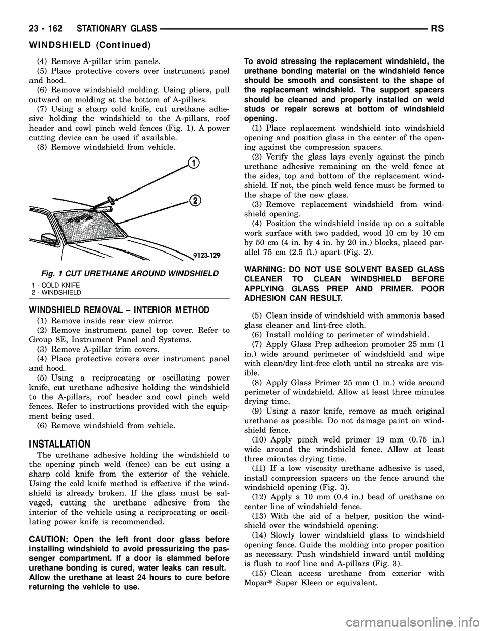
(7) Using a sharp cold knife, cut urethane adhe-
sive holding the windshield to the A-pillars, roof
header and cowl pinch weld fences (Fig. 1). A power
cutting device can be used if available.
(8) Remove windshield from vehicle.
WINDSHIELD REMOVAL ± INTERIOR METHOD
(1) Remove inside rear view mirror.
(2) Remove instrument panel top cover. Refer to
Group 8E, Instrument Panel and Systems.
(3) Remove A-pillar trim covers.
(4) Place protective covers over instrument panel
and hood.
(5) Using a reciprocating or oscillating power
knife, cut urethane adhesive holding the windshield
to the A-pillars, roof header and cowl pinch weld
fences. Refer to instructions provided with the equip-
ment being used.
(6) Remove windshield from vehicle.
INSTALLATION
The urethane adhesive holding the windshield to
the opening pinch weld (fence) can be cut using a
sharp cold knife from the exterior of the vehicle.
Using the cold knife method is effective if the wind-
shield is already broken. If the glass must be sal-
vaged, cutting the urethane adhesive from the
interior of the vehicle using a reciprocating or oscil-
lating power knife is recommended.
CAUTION: Open the left front door glass before
installing windshield to avoid pressurizing the pas-
senger compartment. If a door is slammed before
urethane bonding is cured, water leaks can result.
Allow the urethane at least 24 hours to cure before
returning the vehicle to use.To avoid stressing the replacement windshield, the
urethane bonding material on the windshield fence
should be smooth and consistent to the shape of
the replacement windshield. The support spacers
should be cleaned and properly installed on weld
studs or repair screws at bottom of windshield
opening.
(1) Place replacement windshield into windshield
opening and position glass in the center of the open-
ing against the compression spacers.
(2) Verify the glass lays evenly against the pinch
urethane adhesive remaining on the weld fence at
the sides, top and bottom of the replacement wind-
shield. If not, the pinch weld fence must be formed to
the shape of the new glass.
(3) Remove replacement windshield from wind-
shield opening.
(4) Position the windshield inside up on a suitable
work surface with two padded, wood 10 cm by 10 cm
by 50 cm (4 in. by 4 in. by 20 in.) blocks, placed par-
allel 75 cm (2.5 ft.) apart (Fig. 2).
WARNING: DO NOT USE SOLVENT BASED GLASS
CLEANER TO CLEAN WINDSHIELD BEFORE
APPLYING GLASS PREP AND PRIMER. POOR
ADHESION CAN RESULT.
(5) Clean inside of windshield with ammonia based
glass cleaner and lint-free cloth.
(6) Install molding to perimeter of windshield.
(7) Apply Glass Prep adhesion promoter 25 mm (1
in.) wide around perimeter of windshield and wipe
with clean/dry lint-free cloth until no streaks are vis-
ible.
(8) Apply Glass Primer 25 mm (1 in.) wide around
perimeter of windshield. Allow at least three minutes
drying time.
(9) Using a razor knife, remove as much original
urethane as possible. Do not damage paint on wind-
shield fence.
(10) Apply pinch weld primer 19 mm (0.75 in.)
wide around the windshield fence. Allow at least
three minutes drying time.
(11) If a low viscosity urethane adhesive is used,
install compression spacers on the fence around the
windshield opening (Fig. 3).
(12) Apply a 10 mm (0.4 in.) bead of urethane on
center line of windshield fence.
(13) With the aid of a helper, position the wind-
shield over the windshield opening.
(14) Slowly lower windshield glass to windshield
opening fence. Guide the molding into proper position
as necessary. Push windshield inward until molding
is flush to roof line and A-pillars (Fig. 3).
(15) Clean access urethane from exterior with
MopartSuper Kleen or equivalent.
Fig. 1 CUT URETHANE AROUND WINDSHIELD
1 - COLD KNIFE
2 - WINDSHIELD
23 - 162 STATIONARY GLASSRS
WINDSHIELD (Continued)
Page 1948 of 2339
SUNROOF
TABLE OF CONTENTS
page page
SUNROOF
DESCRIPTION........................169
DIAGNOSIS AND TESTING
SUNROOF DIAGNOSIS AND TESTING....169
DRAIN TUBE
REMOVAL............................172
INSTALLATION........................172
GLASS PANEL
REMOVAL............................173
INSTALLATION........................173
ADJUSTMENTS
SUNROOF GLASS PANEL ADJUSTMENT . . 173
SUNROOF ASSEMBLY
REMOVAL............................173
INSTALLATION........................173
SUNSHADE
REMOVAL............................173INSTALLATION........................173
WIND DEFLECTOR
REMOVAL............................174
INSTALLATION........................174
WATER CHANNEL
REMOVAL............................174
INSTALLATION........................174
SUNROOF MOTOR
REMOVAL............................174
INSTALLATION........................174
ADJUSTMENTS
ADJUSTMENT.......................175
SUNROOF SWITCH
REMOVAL............................176
INSTALLATION........................176
SUNROOF
DESCRIPTION
WARNING: Keep fingers and other body parts out
of sunroof opening at all times.
The sun roof features consists of: (Fig. 1)
²Sun roof glass
²Sun roof sun shade
The sunroof power sliding glass panel and sun-
shade can be positioned anywhere along its travel,
rearward of glass panel front edge.
The sunroof is electrically operated from a switch
located in the overhead console. To operate the sun-
roof the ignition switch must be in the Accessory or
On/Run position. Both switchs are a rocker style
design that open or close the sunroof. When pressing
and releasing the open button once, the sunroof will
express open to the comfort stop and the wind deflec-
tor will raise. If the button is pressed a second time,
the sunroof will continue to open to full travel unless
the button is released, at which time it will stop in
that position. Pressing and holding the close button
will close the sunroof. If the close button is released
before the glass fully closes, the sunroof will stop in
that position. The vent switch operates in a similar
manor. The sunroof will also operate for up to fifteen
minutes after the ignition key is turned off for cus-
tomer comfort and convenance while parking.
DIAGNOSIS AND TESTING
SUNROOF DIAGNOSIS AND TESTING
Refer to Sunroof Diagnostic Chart for possible
causes. Before beginning sunroof diagnostics verify
that all other power accessories are in proper operat-
ing condition. If not, a common electrical problem
may exist. Refer to Wiring Diagrams, in this publica-
tion for circuit, splice and component descriptions.
Check the condition of the circuit protection (20 amp
circuit breaker in the Junction Block). Inspect all
wiring connector pins for proper engagement and
continuity. Check for battery voltage at the power
sunroof controller, refer to Wiring Diagrams, for cir-
cuit information. If battery voltage of more than 10
volts is detected at the controller, proceed with the
following tests (the controller will not operate at less
than 10 volts).
Before beginning diagnosis for wind noise or water
leaks, verify that the problem was not caused by
releasing the control switch before the sunroof was
fully closed. The sunroof module has a water-man-
agement system. If however, the sunroof glass is in a
partial closed position, high pressure water may be
forced beyond the water management system bound-
aries and onto the headlining.
RSSUNROOF23 - 169
Page 1949 of 2339
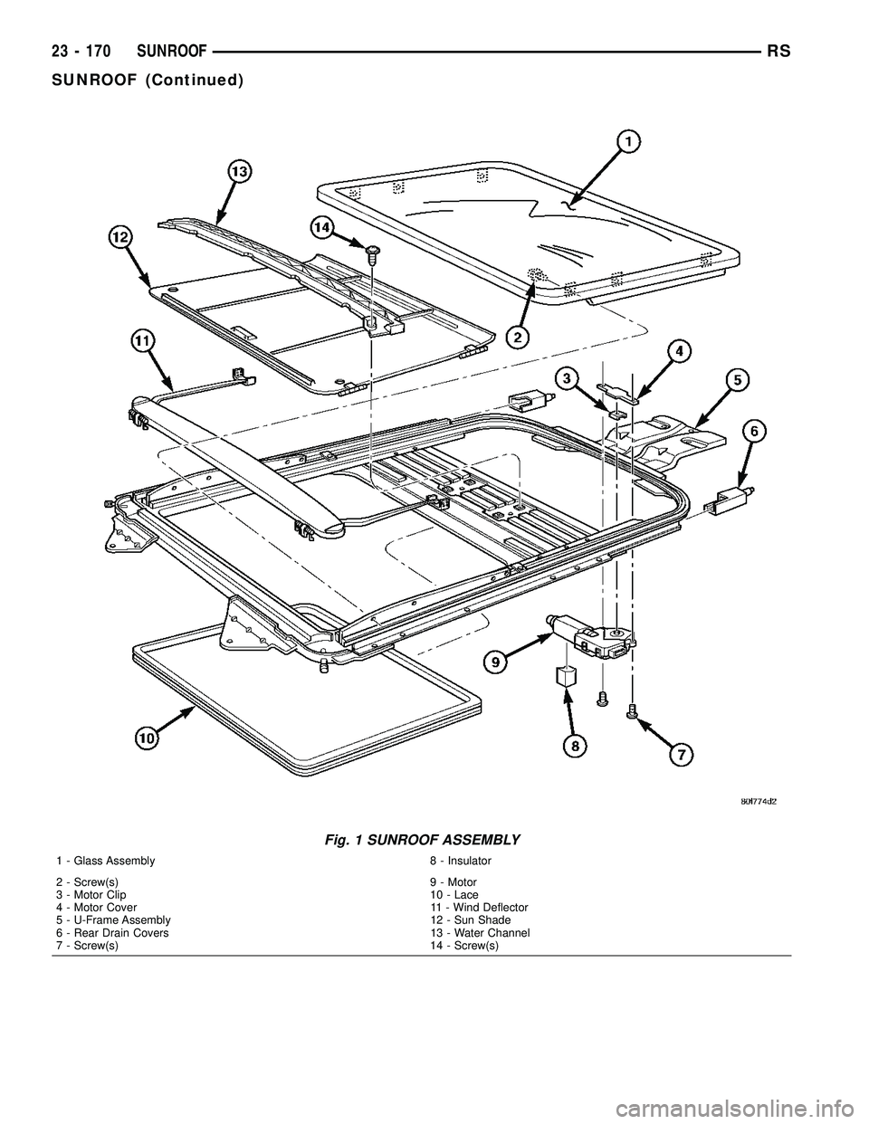
Fig. 1 SUNROOF ASSEMBLY
1 - Glass Assembly 8 - Insulator
2 - Screw(s) 9 - Motor
3 - Motor Clip 10 - Lace
4 - Motor Cover 11 - Wind Deflector
5 - U-Frame Assembly 12 - Sun Shade
6 - Rear Drain Covers 13 - Water Channel
7 - Screw(s) 14 - Screw(s)
23 - 170 SUNROOFRS
SUNROOF (Continued)
Page 1950 of 2339
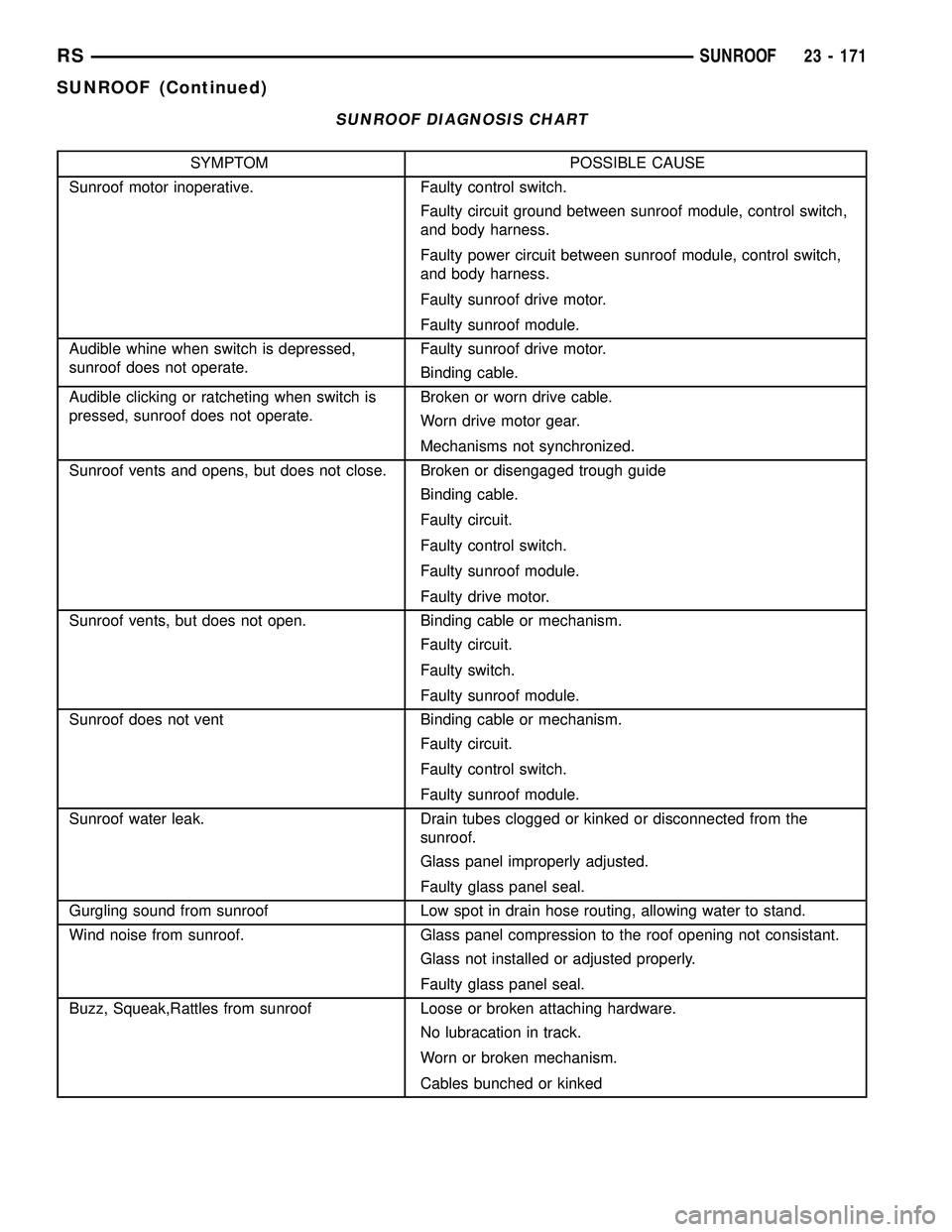
SUNROOF DIAGNOSIS CHART
SYMPTOM POSSIBLE CAUSE
Sunroof motor inoperative. Faulty control switch.
Faulty circuit ground between sunroof module, control switch,
and body harness.
Faulty power circuit between sunroof module, control switch,
and body harness.
Faulty sunroof drive motor.
Faulty sunroof module.
Audible whine when switch is depressed,
sunroof does not operate.Faulty sunroof drive motor.
Binding cable.
Audible clicking or ratcheting when switch is
pressed, sunroof does not operate.Broken or worn drive cable.
Worn drive motor gear.
Mechanisms not synchronized.
Sunroof vents and opens, but does not close. Broken or disengaged trough guide
Binding cable.
Faulty circuit.
Faulty control switch.
Faulty sunroof module.
Faulty drive motor.
Sunroof vents, but does not open. Binding cable or mechanism.
Faulty circuit.
Faulty switch.
Faulty sunroof module.
Sunroof does not vent Binding cable or mechanism.
Faulty circuit.
Faulty control switch.
Faulty sunroof module.
Sunroof water leak. Drain tubes clogged or kinked or disconnected from the
sunroof.
Glass panel improperly adjusted.
Faulty glass panel seal.
Gurgling sound from sunroof Low spot in drain hose routing, allowing water to stand.
Wind noise from sunroof. Glass panel compression to the roof opening not consistant.
Glass not installed or adjusted properly.
Faulty glass panel seal.
Buzz, Squeak,Rattles from sunroof Loose or broken attaching hardware.
No lubracation in track.
Worn or broken mechanism.
Cables bunched or kinked
RSSUNROOF23 - 171
SUNROOF (Continued)
Page 1951 of 2339
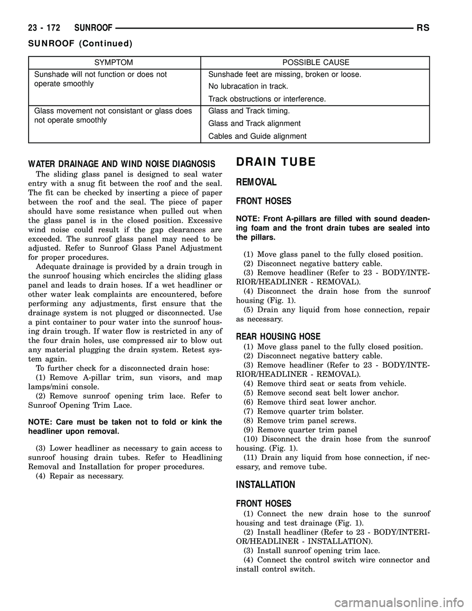
SYMPTOM POSSIBLE CAUSE
Sunshade will not function or does not
operate smoothlySunshade feet are missing, broken or loose.
No lubracation in track.
Track obstructions or interference.
Glass movement not consistant or glass does
not operate smoothlyGlass and Track timing.
Glass and Track alignment
Cables and Guide alignment
WATER DRAINAGE AND WIND NOISE DIAGNOSIS
The sliding glass panel is designed to seal water
entry with a snug fit between the roof and the seal.
The fit can be checked by inserting a piece of paper
between the roof and the seal. The piece of paper
should have some resistance when pulled out when
the glass panel is in the closed position. Excessive
wind noise could result if the gap clearances are
exceeded. The sunroof glass panel may need to be
adjusted. Refer to Sunroof Glass Panel Adjustment
for proper procedures.
Adequate drainage is provided by a drain trough in
the sunroof housing which encircles the sliding glass
panel and leads to drain hoses. If a wet headliner or
other water leak complaints are encountered, before
performing any adjustments, first ensure that the
drainage system is not plugged or disconnected. Use
a pint container to pour water into the sunroof hous-
ing drain trough. If water flow is restricted in any of
the four drain holes, use compressed air to blow out
any material plugging the drain system. Retest sys-
tem again.
To further check for a disconnected drain hose:
(1) Remove A-pillar trim, sun visors, and map
lamps/mini console.
(2) Remove sunroof opening trim lace. Refer to
Sunroof Opening Trim Lace.
NOTE: Care must be taken not to fold or kink the
headliner upon removal.
(3) Lower headliner as necessary to gain access to
sunroof housing drain tubes. Refer to Headlining
Removal and Installation for proper procedures.
(4) Repair as necessary.
DRAIN TUBE
REMOVAL
FRONT HOSES
NOTE: Front A-pillars are filled with sound deaden-
ing foam and the front drain tubes are sealed into
the pillars.
(1) Move glass panel to the fully closed position.
(2) Disconnect negative battery cable.
(3) Remove headliner (Refer to 23 - BODY/INTE-
RIOR/HEADLINER - REMOVAL).
(4) Disconnect the drain hose from the sunroof
housing (Fig. 1).
(5) Drain any liquid from hose connection, repair
as necessary.
REAR HOUSING HOSE
(1) Move glass panel to the fully closed position.
(2) Disconnect negative battery cable.
(3) Remove headliner (Refer to 23 - BODY/INTE-
RIOR/HEADLINER - REMOVAL).
(4) Remove third seat or seats from vehicle.
(5) Remove second seat belt lower anchor.
(6) Remove third seat lower anchor.
(7) Remove quarter trim bolster.
(8) Remove trim panel screws.
(9) Remove quarter trim panel
(10) Disconnect the drain hose from the sunroof
housing. (Fig. 1).
(11) Drain any liquid from hose connection, if nec-
essary, and remove tube.
INSTALLATION
FRONT HOSES
(1) Connect the new drain hose to the sunroof
housing and test drainage (Fig. 1).
(2) Install headliner (Refer to 23 - BODY/INTERI-
OR/HEADLINER - INSTALLATION).
(3) Install sunroof opening trim lace.
(4) Connect the control switch wire connector and
install control switch.
23 - 172 SUNROOFRS
SUNROOF (Continued)