2005 CHRYSLER VOYAGER roof
[x] Cancel search: roofPage 1125 of 2339

CONNECTOR NAME/NUMBER COLOR LOCATION FIG.
Right Sliding Door Motor BK At Sliding Door 45
Right Speed Control Switch WT At Steering Wheel N/S
Right Turn Signal Lamp (Export) OR At Lamp N/S
Right Visor/Vanity Lamp BK At Lamp N/S
Sentry Key Remote Entry Module
(SKREEM)BK At Steering Column 20, 21, 22, 23, 31
Siren (United Kingdom) BK Left Front Body N/S
Speed Control Servo (Gas) BK Near Controller Antilock Brake 11, 17, 18
Sunroof Module (Except Export) BK At Sunroof N/S
Sunroof Switch (Except Export) NAT Near Overhead Console N/S
Thatcham Alarm Module (United
Kingdom)BK Top Right Side of Instrument Panel
Near SpeakerN/S
Throttle Position Sensor (Gas) GY On Throttle Body 10, 11, 17
Traction Control Switch BK Rear of Swtich 21, 22, 31
Trailer Tow Connector (Except
Export)Left Quarter Panel N/S
Transmission Control Relay
(Diesel)Near Transmission 16
Transmission Range Sensor DKGY Top of Transmission 14, 19
Transmission Solenoid/Pressure
Switch AssemblyBK Side of Transmission 14, 19
Vehicle Speed Sensor (MTX) BK Rear of Transmission 16
Washer Fluid Level Switch BK Bottom of Reservoir 3
Washer Pump Motor BK Right Fender Well 3
Water in Fuel Sensor (Diesel) BK Left Rear Engine Compartment N/S
Wiper Module DKGY Left Side Cowl 6
GROUNDS
GROUND NUMBER LOCATION FIG.
G100 Body Ground Near Powertrain Control Module N/S
G101 Above Starter 13, 15, 18
G102 Left Headlamp Area 1
G103 Above Starter 15
G200 Left Side of Instrument Panel 20, 21 29
G201 Right Side of Instrument Panel 20, 24, 29
G202 Near Radio N/S
G300 Left B Pillar 32
G301 Right B Pillar 33, 39
G302 Left Rear Quarter 47
G303 Liftgate Ground 49
8W - 91 - 12 8W-91 CONNECTOR/GROUND/SPLICE LOCATIONRS
CONNECTOR/GROUND/SPLICE LOCATION (Continued)
Page 1426 of 2339
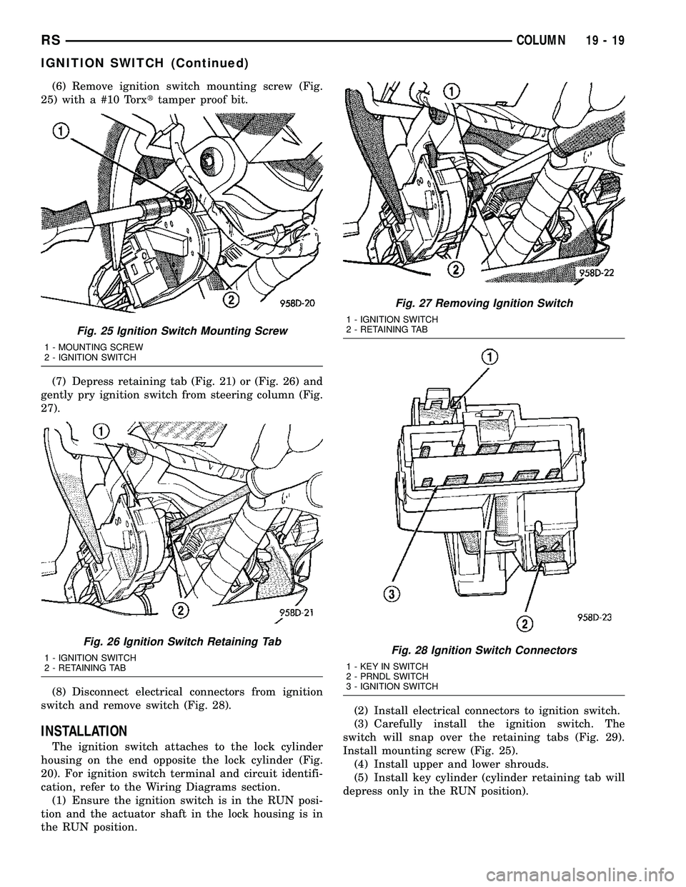
(6) Remove ignition switch mounting screw (Fig.
25) with a #10 Torxttamper proof bit.
(7) Depress retaining tab (Fig. 21) or (Fig. 26) and
gently pry ignition switch from steering column (Fig.
27).
(8) Disconnect electrical connectors from ignition
switch and remove switch (Fig. 28).
INSTALLATION
The ignition switch attaches to the lock cylinder
housing on the end opposite the lock cylinder (Fig.
20). For ignition switch terminal and circuit identifi-
cation, refer to the Wiring Diagrams section.
(1) Ensure the ignition switch is in the RUN posi-
tion and the actuator shaft in the lock housing is in
the RUN position.(2) Install electrical connectors to ignition switch.
(3) Carefully install the ignition switch. The
switch will snap over the retaining tabs (Fig. 29).
Install mounting screw (Fig. 25).
(4) Install upper and lower shrouds.
(5) Install key cylinder (cylinder retaining tab will
depress only in the RUN position).
Fig. 25 Ignition Switch Mounting Screw
1 - MOUNTING SCREW
2 - IGNITION SWITCH
Fig. 26 Ignition Switch Retaining Tab
1 - IGNITION SWITCH
2 - RETAINING TAB
Fig. 27 Removing Ignition Switch
1 - IGNITION SWITCH
2 - RETAINING TAB
Fig. 28 Ignition Switch Connectors
1 - KEY IN SWITCH
2 - PRNDL SWITCH
3 - IGNITION SWITCH
RSCOLUMN19-19
IGNITION SWITCH (Continued)
Page 1780 of 2339
BODY
TABLE OF CONTENTS
page page
BODY
DESCRIPTION - VEHICLE IDENTIFICATION....1
WARNING
SAFETY PRECAUTIONS AND WARNINGS . . . 1
DIAGNOSIS AND TESTING
WATER LEAKS........................1
WIND NOISE..........................2
STANDARD PROCEDURE
STANDARD PROCEDURE - PLASTIC BODY
PANEL REPAIR........................3
STANDARD PROCEDURE - HEAT STAKING . . 9
SPECIFICATIONS
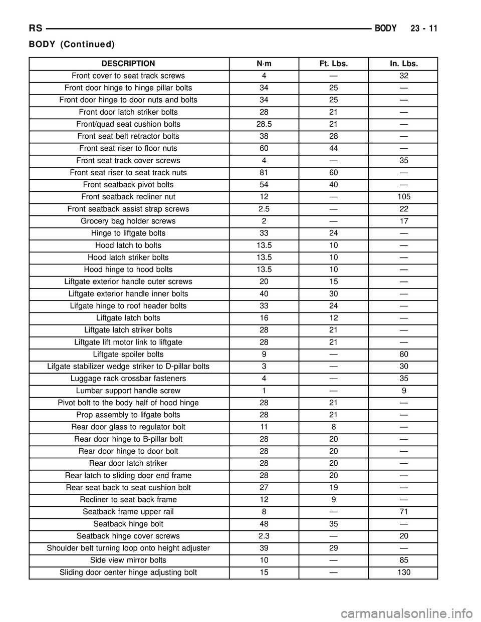
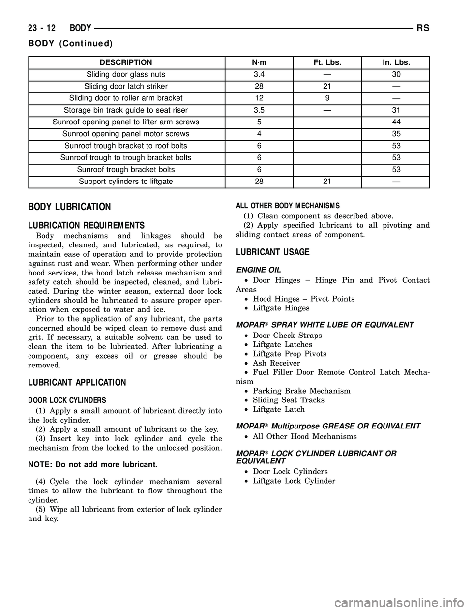
TORQUE............................10
BODY LUBRICATION...................12
SPECIAL TOOLS
BODY..............................13DOOR - FRONT.........................14
DOORS - SLIDING.......................24
DECKLID/HATCH/LIFTGATE/TAILGATE.......40
EXTERIOR.............................45
HOOD.................................62
INSTRUMENT PANEL.....................65
INTERIOR..............................78
PAINT................................100
SEATS...............................102
STATIONARY GLASS....................161
WEATHERSTRIP/SEALS..................166
SUNROOF.............................169
BODY STRUCTURE.....................177
BODY
DESCRIPTION - VEHICLE IDENTIFICATION
Throughout this group, references to the
DaimlerChrysler Corporation vehicle family identifi-
cation code are used when describing a procedure
that is unique to that vehicle. Refer to Introduction
Group of this manual for detailed information on
vehicle identification. If a procedure is common to all
vehicles covered in this manual, no reference will be
made to a vehicle family code.
WARNING
SAFETY PRECAUTIONS AND WARNINGS
WARNING: USE A OSHA APPROVED BREATHING
FILTER WHEN SPRAYING PAINT OR SOLVENTS IN
A CONFINED AREA. PERSONAL INJURY CAN
RESULT.
AVOID PROLONGED SKIN CONTACT WITH PETRO-
LEUM OR ALCOHOL ± BASED CLEANING SOL-
VENTS. PERSONAL INJURY CAN RESULT.
DO NOT STAND UNDER A HOISTED VEHICLE THAT
IS NOT PROPERLY SUPPORTED ON SAFETY
STANDS. PERSONAL INJURY CAN RESULT.
CAUTION: When holes must be drilled or punched
in an inner body panel, verify depth of space to the
outer body panel, electrical wiring, or other compo-nents. Damage to vehicle can result.
Do not weld exterior panels unless combustible
material on the interior of vehicle is removed from
the repair area. Fire or hazardous conditions, can
result.
Always have a fire extinguisher ready for use when
welding.
Disconnect the negative (-) cable clamp from the
battery when servicing electrical components that
are live when the ignition is OFF. Damage to electri-
cal system can result.
Do not use abrasive chemicals or compounds on
painted surfaces. Damage to finish can result.
Do not use harsh alkaline based cleaning solvents
on painted or upholstered surfaces. Damage to fin-
ish or color can result.
Do not hammer or pound on plastic trim panel
when servicing interior trim. Plastic panels can
break.
DIAGNOSIS AND TESTING
WATER LEAKS
Water leaks can be caused by poor sealing,
improper body component alignment, body seam
porosity, missing plugs, or blocked drain holes. Cen-
trifugal and gravitational force can cause water to
drip from a location away from the actual leak point,
making leak detection difficult. All body sealing
points should be water tight in normal wet-driving
conditions. Water flowing downward from the front of
RSBODY23-1
Page 1790 of 2339
DESCRIPTION N´m Ft. Lbs. In. Lbs.
Front cover to seat track screws 4 Ð 32
Front door hinge to hinge pillar bolts 34 25 Ð
Front door hinge to door nuts and bolts 34 25 Ð
Front door latch striker bolts 28 21 Ð
Front/quad seat cushion bolts 28.5 21 Ð
Front seat belt retractor bolts 38 28 Ð
Front seat riser to floor nuts 60 44 Ð
Front seat track cover screws 4 Ð 35
Front seat riser to seat track nuts 81 60 Ð
Front seatback pivot bolts 54 40 Ð
Front seatback recliner nut 12 Ð 105
Front seatback assist strap screws 2.5 Ð 22
Grocery bag holder screws 2 Ð 17
Hinge to liftgate bolts 33 24 Ð
Hood latch to bolts 13.5 10 Ð
Hood latch striker bolts 13.5 10 Ð
Hood hinge to hood bolts 13.5 10 Ð
Liftgate exterior handle outer screws 20 15 Ð
Liftgate exterior handle inner bolts 40 30 Ð
Lifgate hinge to roof header bolts 33 24 Ð
Liftgate latch bolts 16 12 Ð
Liftgate latch striker bolts 28 21 Ð
Liftgate lift motor link to liftgate 28 21 Ð
Liftgate spoiler bolts 9 Ð 80
Lifgate stabilizer wedge striker to D-pillar bolts 3 Ð 30
Luggage rack crossbar fasteners 4 Ð 35
Lumbar support handle screw 1 Ð 9
Pivot bolt to the body half of hood hinge 28 21 Ð
Prop assembly to lifgate bolts 28 21 Ð
Rear door glass to regulator bolt 11 8 Ð
Rear door hinge to B-pillar bolt 28 20 Ð
Rear door hinge to door bolt 28 20 Ð
Rear door latch striker 28 20 Ð
Rear latch to sliding door end frame 28 20 Ð
Rear seat back to seat cushion bolt 27 19 Ð
Recliner to seat back frame 12 9 Ð
Seatback frame upper rail 8 Ð 71
Seatback hinge bolt 48 35 Ð
Seatback hinge cover screws 2.3 Ð 20
Shoulder belt turning loop onto height adjuster 39 29 Ð
Side view mirror bolts 10 Ð 85
Sliding door center hinge adjusting bolt 15 Ð 130
RSBODY23-11
BODY (Continued)
Page 1791 of 2339
DESCRIPTION N´m Ft. Lbs. In. Lbs.
Sliding door glass nuts 3.4 Ð 30
Sliding door latch striker 28 21 Ð
Sliding door to roller arm bracket 12 9 Ð
Storage bin track guide to seat riser 3.5 Ð 31
Sunroof opening panel to lifter arm screws 5 44
Sunroof opening panel motor screws 4 35
Sunroof trough bracket to roof bolts 6 53
Sunroof trough to trough bracket bolts 6 53
Sunroof trough bracket bolts 6 53
Support cylinders to liftgate 28 21 Ð
BODY LUBRICATION
LUBRICATION REQUIREMENTS
Body mechanisms and linkages should be
inspected, cleaned, and lubricated, as required, to
maintain ease of operation and to provide protection
against rust and wear. When performing other under
hood services, the hood latch release mechanism and
safety catch should be inspected, cleaned, and lubri-
cated. During the winter season, external door lock
cylinders should be lubricated to assure proper oper-
ation when exposed to water and ice.
Prior to the application of any lubricant, the parts
concerned should be wiped clean to remove dust and
grit. If necessary, a suitable solvent can be used to
clean the item to be lubricated. After lubricating a
component, any excess oil or grease should be
removed.
LUBRICANT APPLICATION
DOOR LOCK CYLINDERS
(1) Apply a small amount of lubricant directly into
the lock cylinder.
(2) Apply a small amount of lubricant to the key.
(3) Insert key into lock cylinder and cycle the
mechanism from the locked to the unlocked position.
NOTE: Do not add more lubricant.
(4) Cycle the lock cylinder mechanism several
times to allow the lubricant to flow throughout the
cylinder.
(5) Wipe all lubricant from exterior of lock cylinder
and key.ALL OTHER BODY MECHANISMS
(1) Clean component as described above.
(2) Apply specified lubricant to all pivoting and
sliding contact areas of component.
LUBRICANT USAGE
ENGINE OIL
²Door Hinges ± Hinge Pin and Pivot Contact
Areas
²Hood Hinges ± Pivot Points
²Liftgate Hinges
MOPARTSPRAY WHITE LUBE OR EQUIVALENT
²Door Check Straps
²Liftgate Latches
²Liftgate Prop Pivots
²Ash Receiver
²Fuel Filler Door Remote Control Latch Mecha-
nism
²Parking Brake Mechanism
²Sliding Seat Tracks
²Liftgate Latch
MOPARTMultipurpose GREASE OR EQUIVALENT
²All Other Hood Mechanisms
MOPARTLOCK CYLINDER LUBRICANT OR
EQUIVALENT
²Door Lock Cylinders
²Liftgate Lock Cylinder
23 - 12 BODYRS
BODY (Continued)
Page 1810 of 2339
(4) Check door for height using character lines as
a reference. Also check roof contour as a controlling
factor.
Using the procedures noted below, adjust the side
door in the order the individual steps are called out.
DOOR FLUSHNESS ADJUSTMENT
(1) Check sliding door flushness at the C-pillar
striker.
(2) If the sliding door is under or over flush,
remove striker assembly and move thread plate over
keeping one bolt in plate so it will not fall between
inner and outer panels.
(3) Adjust the C-pillar striker in or out until the
door is flush. Then, the on size hole can be elongated
in the direction required. This can be done by grind-
ing or filing the sheet metal and then painting raw
edge to prevent rusting.
(4) Check upper B-pillar flushness to A-pillar
cover.
(5) The sliding door upper hinge can only be
moved outboard by addinga1mmshim behind the
hinge mounting area once the two attachment bolts
are removed and reinstalled.
(6) Check flushness at upper C-pillar.
(7) If upper C-pillar flushness is out of specifica-
tion use a heavy rubber mallet on the door assembly
until door is in specifications.
DOOR GAP ADJUSTMENT - UP/DOWN
(1) Check height of sliding door at the B-pillar and
C-pillar to determine which area is contributing the
greatest to the incorrect gaps.
(2) Visually inspect the sliding door for fitting low
at the top of the door by checking the alignment of
the top contour of the door to the quarter panel.
(3) If the sliding door is high at the C-pillar.
(a) Open the door to mid-point of travel.
(b) Mark outline of center hinge on sliding door
to assist in making adjustments.
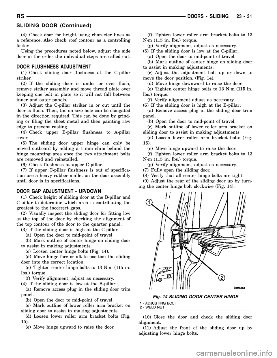
(c) Loosen center hinge bolts (Fig. 14).
(d) Move hinge fore or aft to position the sliding
door into the correct location.
(e) Tighten center hinge bolts to 13 N´m (115 in.
lbs.) torque.
(f) Verify alignment, adjust as necessary.
(4) If the sliding door is low at the B-pillar ;
(a) Remove access plug in the sliding door trim
panel.
(b) Open the door to mid-point of travel.
(c) Mark outline of lower roller arm bracket on
sliding door to assist in making adjustments.
(d) Loosen lower roller arm bracket bolts (Fig.
15).
(e) Move hinge upward to raise the door.(f) Tighten lower roller arm bracket bolts to 13
N´m (115 in. lbs.) torque.
(g) Verify alignment, adjust as necessary.
(5) If the sliding door is low at the C-pillar;
(a) Open the door to mid-point of travel.
(b) Mark outline of center hinge on sliding door
to assist in making adjustments.
(c) Adjust the adjustment bolt up or down to
move the door position. (Fig. 14).
(d) Move hinge downward to raise the door.
(e) Tighten center hinge bolts to 13 N´m (115 in.
lbs.) torque.
(f) Verify alignment adjust as necessary.
(6) If the sliding door is high at the B-pillar;
(a) Remove access plug in the sliding door trim
panel.
(b) Open the door to mid-point of travel.
(c) Mark outline of lower roller arm bracket on
sliding door to assist in making adjustments.
(d) Loosen lower roller arm bracket bolts (Fig.
15).
(e) Move hinge upward to raise the door.
(f) Tighten lower roller arm bracket bolts to 13
N´m (115 in. lbs.) torque.
(g) Verify alignment, adjust as necessary.
(7) Fully open the sliding door.
(8) Verify that all center hinge bolts are tight.
(9) Adjust the rear of the sliding door up by turn-
ing the center hinge bolt clockwise (Fig. 14).
(10) Close the door and check the sliding door
alignment.
(11) Adjust the front of the sliding door up by
adjusting lower hinge bolts.
Fig. 14 SLIDING DOOR CENTER HINGE
1 - ADJUSTING BOLT
2 - WELD NUT
RSDOORS - SLIDING23-31
SLIDING DOOR (Continued)
Page 1815 of 2339
INSTALLATION
(1) Position outside door handle on vehicle.
(2) Install nuts attaching outside door handle to
outer door panel.
(3) Engage clip attaching linkage to outside door
handle.
(4) Engage rigging cam to latch/lock control mech-
anism.
(5) Move clip on latch/lock control to bottom of slot
and engage linkage to latch/lock control.
(6) Verify sliding door operation. Adjust as neces-
sary.
(7) Place the watershield into position and press
securely to adhesive making sure to properly route
wiring and linkages.
(8) Install sliding door stop bumper. (Refer to 23 -
BODY/DOORS - SLIDING/STOP BUMPER -
INSTALLATION)
(9) Install sliding door trim panel. (Refer to 23 -
BODY/DOORS - SLIDING/TRIM PANEL - INSTAL-
LATION)
UPPER HINGE
REMOVAL
(1) Open sliding door, do not latch open.
(2) Remove screw attaching upper stop bracket to
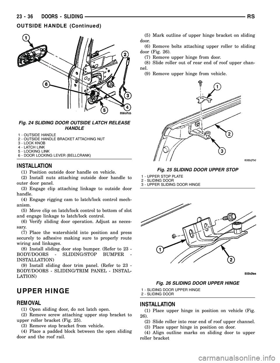
upper roller bracket (Fig. 25).
(3) Remove stop bracket from vehicle.
(4) Place a padded block between the open sliding
door and the roof rail.(5) Mark outline of upper hinge bracket on sliding
door.
(6) Remove bolts attaching upper roller to sliding
door (Fig. 26).
(7) Remove upper hinge from door.
(8) Slide roller out of rear end of roof upper chan-
nel.
(9) Remove upper hinge from vehicle.INSTALLATION
(1) Place upper hinge in position on vehicle (Fig.
26).
(2) Slide roller into rear end of roof upper channel.
(3) Place upper hinge in position on door.
(4) Align outline marks on sliding door to upper
roller bracket
Fig. 24 SLIDING DOOR OUTSIDE LATCH RELEASE
HANDLE
1 - OUTSIDE HANDLE
2 - OUTSIDE HANDLE BRACKET ATTACHING NUT
3 - LOCK KNOB
4 - LATCH LINK
5 - LOCKING LINK
6 - DOOR LOCKING LEVER (BELLCRANK)
Fig. 25 SLIDING DOOR UPPER STOP
1 - UPPER STOP PLATE
2 - SLIDING DOOR
3 - UPPER SLIDING DOOR HINGE
Fig. 26 SLIDING DOOR UPPER HINGE
1 - SLIDING DOOR UPPER HINGE
2 - SLIDING DOOR
23 - 36 DOORS - SLIDINGRS
OUTSIDE HANDLE (Continued)
Page 1816 of 2339
(5) Install bolts attaching upper hinge to sliding
door.
(6) Remove padded block from between sliding
door and roof rail.
(7) Place stop bracket in position on vehicle.
(8) Install screw attaching upper stop bracket to
upper roller bracket (Fig. 25).
(9) Verify sliding door alignment and operation.
Adjust as necessary. (Refer to 23 - BODY/DOORS -
SLIDING/SLIDING DOOR - ADJUSTMENTS)
OUTSIDE HANDLE CABLE
REMOVAL
NOTE: For power sliding door procedures refer to
POWER SLIDING DOOR SYSTEM in the ELECTRI-
CAL section.
(1) Disconnect and isolate the negative battery
cable.
(2) Remove stop bumper (Refer to 23 - BODY/
DOORS - SLIDING/STOP BUMPER - REMOVAL).
(3) Remove the appropriate side door trim panel.
(Refer to 23 - BODY/DOORS - SLIDING/TRIM
PANEL - REMOVAL)
(4) Peel watershield away from adhesive around
perimeter of inner door panel.
CAUTION: Make note of cable routing and foam
insulator placement. This will prove helpful when
reinstalling replacement cable. Be certain replace-
ment cable is routed and retained correctly.
(5) Trace the outside handle cable along its routing
path and disconnect from its retaining clips.
(6) Disconnect the outside handle cable from the
latch assembly. Gently pry cable sleeve retainer out
of the latch mounting bracket and then unhook
swedged cable end from the latch link.
(7) Disconnect the outside handle cable from the
handle assembly. Gently pry cable sleeve retainer out
of the handle bracket and then unhook swedged
cable end from the handle link.
(8) Remove the outside handle cable from the side
door.
INSTALLATION
NOTE: For power sliding door procedures refer to
POWER SLIDING DOOR SYSTEM in the ELECTRI-
CAL section.
(1) Match the replacement cable up against the old
cable to verify the correct part.(2) Position the outside handle cable on the side
door.
(3) Connect the outside handle cable on the handle
assembly. Hook the swedged cable end on the handle
link and gently push the cable sleeve retainer in the
handle bracket.
NOTE: The outside handle cable is marked with red
tape. It must be attached to the latch at the lowest
point. This is marked with a ªRº on the latch.
(4) Connect the outside handle cable on the latch
assembly. Hook the swedged cable end on the latch
link and gently push the cable sleeve retainer in the
latch bracket.
(5) Trace the outside handle cable along its routing
path and install on its retaining clips and position
foam insulators. Use previously made schematic as a
guide or remove the opposite side door trim panel
and use that door as a guide.
CAUTION: Be certain replacement cable is routed
and retained correctly and foam insulators are
properly positioned.
(6) Place the watershield into position and press
securely to adhesive making sure to properly route
wiring and linkages.
(7) Install the appropriate side door trim panel on
the vehicle. (Refer to 23 - BODY/DOORS - SLIDING/
TRIM PANEL - INSTALLATION)
(8) Install stop bumper (Refer to 23 - BODY/
DOORS - SLIDING/STOP BUMPER - INSTALLA-
TION).
(9) Connect the negative battery cable.
INSIDE HANDLE CABLE
REMOVAL
NOTE: For power sliding door procedures refer to
POWER SLIDING DOOR SYSTEM in the ELECTRI-
CAL section.
(1) Disconnect and isolate the negative battery
cable.
(2) Remove the appropriate side door trim panel
from the vehicle. (Refer to 23 - BODY/DOORS -
SLIDING/TRIM PANEL - REMOVAL)
(3) Peel watershield away from adhesive around
perimeter of inner door panel.
(4) Remove the inside handle assembly from the
side door. (Refer to 23 - BODY/DOORS - SLIDING/
INSIDE LATCH HANDLE - REMOVAL)
(5) Disconnect the inside handle cable from the
handle assembly. Gently pry cable sleeve retainer out
RSDOORS - SLIDING23-37
UPPER HINGE (Continued)