Page 2015 of 2339

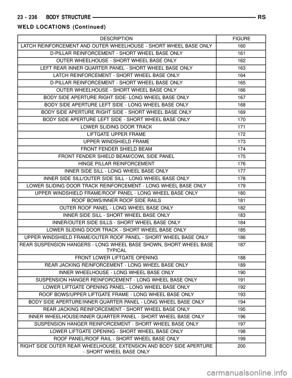
DESCRIPTION FIGURE
LATCH REINFORCEMENT AND OUTER WHEELHOUSE - SHORT WHEEL BASE ONLY 160
D-PILLAR REINFORCEMENT - SHORT WHEEL BASE ONLY 161
OUTER WHEELHOUSE - SHORT WHEEL BASE ONLY 162
LEFT REAR INNER QUARTER PANEL - SHORT WHEEL BASE ONLY 163
LATCH REINFORCEMENT - SHORT WHEEL BASE ONLY 164
D-PILLAR REINFORCEMENT - SHORT WHEEL BASE ONLY 165
OUTER WHEELHOUSE - SHORT WHEEL BASE ONLY 166
BODY SIDE APERTURE RIGHT SIDE- LONG WHEEL BASE ONLY 167
BODY SIDE APERTURE LEFT SIDE - LONG WHEEL BASE ONLY 168
BODY SIDE APERTURE RIGHT SIDE - SHORT WHEEL BASE ONLY 169
BODY SIDE APERTURE LEFT SIDE - SHORT WHEEL BASE ONLY 170
LOWER SLIDING DOOR TRACK 171
LIFTGATE UPPER FRAME 172
UPPER WINDSHIELD FRAME 173
FRONT FENDER SHIELD BEAM 174
FRONT FENDER SHIELD BEAM/COWL SIDE PANEL 175
HINGE PILLAR REINFORCEMENT 176
INNER SIDE SILL - LONG WHEEL BASE ONLY 177
INNER SIDE SILL/OUTER SIDE SILL - LONG WHEEL BASE ONLY 178
LOWER SLIDING DOOR TRACK REINFORCEMENT - LONG WHEEL BASE ONLY 179
UPPER WINDSHIELD FRAME/ROOF PANEL - LONG WHEEL BASE ONLY 180
ROOF BOWS/INNER ROOF SIDE RAILS 181
OUTER ROOF PANEL - LONG WHEEL BASE ONLY 182
INNER SIDE SILL - SHORT WHEEL BASE ONLY 183
INNER/OUTER SIDE SILLS - SHORT WHEEL BASE ONLY 184
LOWER SLIDING DOOR TRACK - SHORT WHEEL BASE ONLY 185
UPPER WINDSHIELD FRAME/OUTER ROOF PANEL - SHORT WHEEL BASE ONLY 186
REAR SUSPENSION HANGERS - LONG WHEEL BASE SHOWN, SHORT WHEEL BASE
TYPICAL187
FRONT LOWER LIFTGATE OPENING 188
REAR JACKING REINFORCEMENT - LONG WHEEL BASE ONLY 189
INNER WHEELHOUSE - LONG WHEEL BASE ONLY 190
SUSPENSION HANGER REINFORCEMENT - LONG WHEEL BASE ONLY 191
LOWER LIFTGATE OPENING PANEL - LONG WHEEL BASE ONLY 192
ROOF BOWS/UPPER LIFTGATE FRAME - LONG WHEEL BASE ONLY 193
BODY SIDE APERTURE/INNER QUARTER PANEL - LONG WHEEL BASE ONLY 194
REAR JACKING REINFORCEMENT - SHORT WHEEL BASE ONLY 195
INNER WHEELHOUSE/INNER QUARTER PANEL - SHORT WHEEL BASE ONLY 196
SUSPENSION HANGER REINFORCEMENT - SHORT WHEEL BASE ONLY 197
LOWER LIFTGATE OPENING - SHORT WHEEL BASE ONLY 198
ROOF PANEL/ROOF RAIL - SHORT WHEEL BASE ONLY 199
RIGHT SIDE OUTER REAR WHEELHOUSE, EXTENSION AND BODY SIDE APERTURE
- SHORT WHEEL BASE ONLY200
23 - 236 BODY STRUCTURERS
WELD LOCATIONS (Continued)
Page 2079 of 2339
Fig. 158 ROOF BOW EXTENSION - LONG WHEEL BASE ONLY
23 - 300 BODY STRUCTURERS
WELD LOCATIONS (Continued)
Page 2100 of 2339
Fig. 180 UPPER WINDSHIELD FRAME/ROOF PANEL - LONG WHEEL BASE ONLY
Fig. 181 ROOF BOWS/INNER ROOF SIDE RAILS
RSBODY STRUCTURE23 - 321
WELD LOCATIONS (Continued)
Page 2101 of 2339
Fig. 182 OUTER ROOF PANEL - LONG WHEEL BASE ONLY
23 - 322 BODY STRUCTURERS
WELD LOCATIONS (Continued)
Page 2105 of 2339
Fig. 186 UPPER WINDSHIELD FRAME/OUTER ROOF PANEL - SHORT WHEEL BASE ONLY
23 - 326 BODY STRUCTURERS
WELD LOCATIONS (Continued)
Page 2111 of 2339
Fig. 193 ROOF BOWS/UPPER LIFTGATE FRAME - LONG WHEEL BASE ONLY
23 - 332 BODY STRUCTURERS
WELD LOCATIONS (Continued)
Page 2117 of 2339
Fig. 199 ROOF PANEL/ROOF RAIL - SHORT WHEEL BASE ONLY
23 - 338 BODY STRUCTURERS
WELD LOCATIONS (Continued)
Page 2207 of 2339

DISTRIBUTION - REAR
TABLE OF CONTENTS
page page
AIR OUTLETS
DESCRIPTION.........................56
REMOVAL.............................56
INSTALLATION.........................56
DISTRIBUTION DUCT
REMOVAL.............................57
INSTALLATION.........................57
BLOWER MOTOR
DESCRIPTION.........................57
OPERATION...........................57DIAGNOSIS AND TESTING
REAR BLOWER MOTOR................58
REMOVAL.............................58
INSTALLATION.........................60
HVAC HOUSING
REMOVAL.............................60
INSTALLATION.........................62
REAR FLOOR HEAT DUCT
REMOVAL.............................63
INSTALLATION.........................63
AIR OUTLETS
DESCRIPTION
Based upon the system mode selected, conditioned
air can exit the rear HVAC housing through one or a
combination of the two main housing outlets: air con-
ditioner, or heater. Once the conditioned air exits the
unit housing, it is directed through molded plastic
ducts to the various outlets in the vehicle interior.
These outlets and their locations are as follows:
²Floor Outlets- Three floor outlets with fixed
vanes are located in the right quarter trim panel,
near the floor. These outlets distribute air from the
rear floor heat duct to the intermediate and rear seat
occupants. The floor outlets are integral to the right
quarter trim panel and, if faulty or damaged, the
quarter trim panel must be replaced.
²Overhead Outlets- Four (two right side and
two left side) fully adjustable outlets along the roof
rails distribute air from the rear distribution duct
and the headliner ducts to the intermediate and rear
seat occupants. The headliner ducts are integral to
the headliner panel. Each overhead outlet is housed
in a headliner bezel. The two forward headliner
bezels also feature a courtesy lamp, a fold-away coat
hook, and a fold-away assist handle. The overhead
outlets can be removed from the headliner bezels
individually for service replacement.
REMOVAL
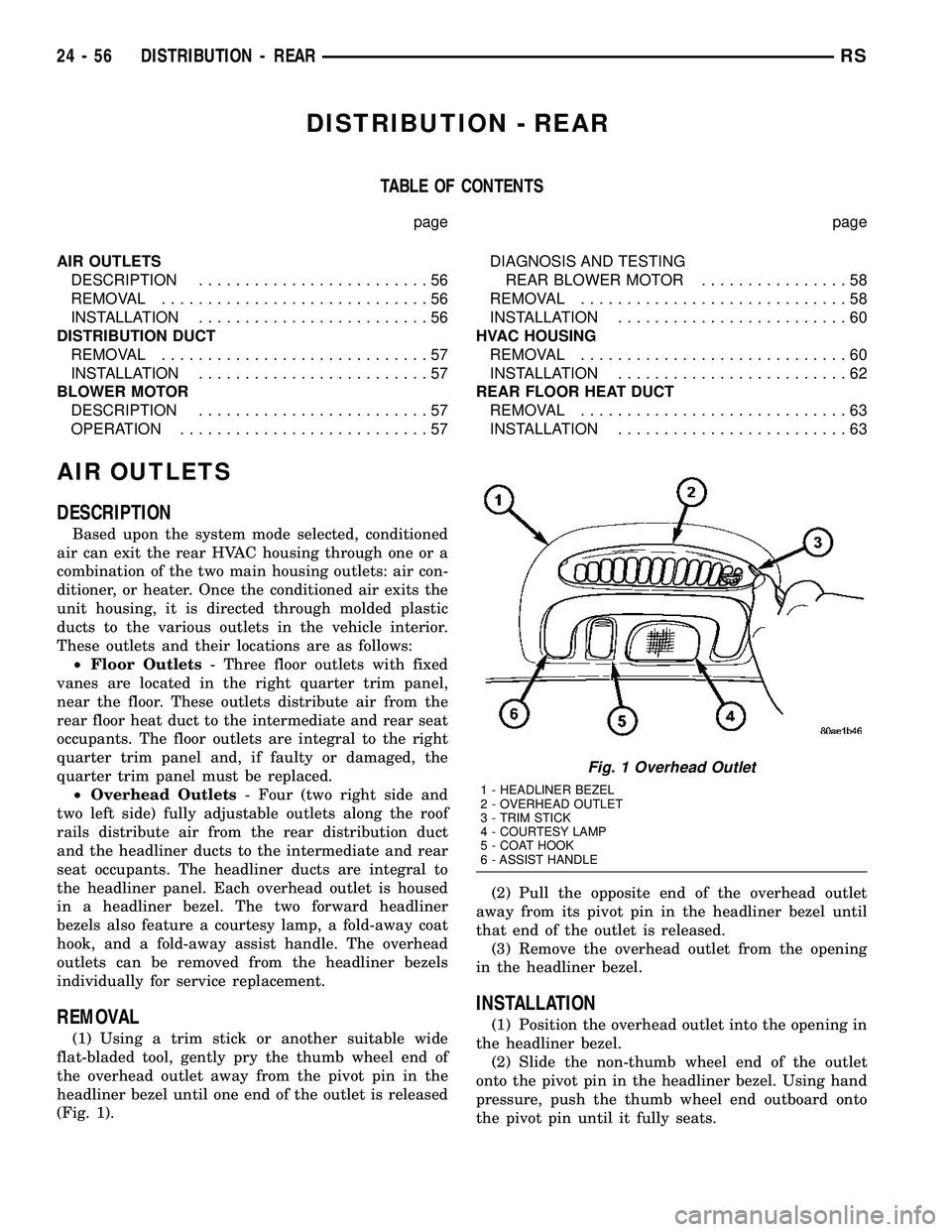
(1) Using a trim stick or another suitable wide
flat-bladed tool, gently pry the thumb wheel end of
the overhead outlet away from the pivot pin in the
headliner bezel until one end of the outlet is released
(Fig. 1).(2) Pull the opposite end of the overhead outlet
away from its pivot pin in the headliner bezel until
that end of the outlet is released.
(3) Remove the overhead outlet from the opening
in the headliner bezel.
INSTALLATION
(1) Position the overhead outlet into the opening in
the headliner bezel.
(2) Slide the non-thumb wheel end of the outlet
onto the pivot pin in the headliner bezel. Using hand
pressure, push the thumb wheel end outboard onto
the pivot pin until it fully seats.
Fig. 1 Overhead Outlet
1 - HEADLINER BEZEL
2 - OVERHEAD OUTLET
3 - TRIM STICK
4 - COURTESY LAMP
5 - COAT HOOK
6 - ASSIST HANDLE
24 - 56 DISTRIBUTION - REARRS