2005 CHRYSLER VOYAGER ail
[x] Cancel search: ailPage 1743 of 2339
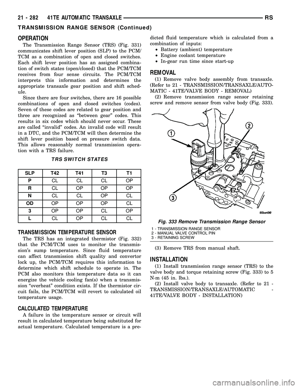
OPERATION
The Transmission Range Sensor (TRS) (Fig. 331)
communicates shift lever position (SLP) to the PCM/
TCM as a combination of open and closed switches.
Each shift lever position has an assigned combina-
tion of switch states (open/closed) that the PCM/TCM
receives from four sense circuits. The PCM/TCM
interprets this information and determines the
appropriate transaxle gear position and shift sched-
ule.
Since there are four switches, there are 16 possible
combinations of open and closed switches (codes).
Seven of these codes are related to gear position and
three are recognized as ªbetween gearº codes. This
results in six codes which should never occur. These
are called ªinvalidº codes. An invalid code will result
in a DTC, and the PCM/TCM will then determine the
shift lever position based on pressure switch data.
This allows reasonably normal transmission opera-
tion with a TRS failure.
TRS SWITCH STATES
SLP T42 T41 T3 T1
PCL CL CL OP
RCL OP OP OP
NCL CL OP CL
ODOP OP OP CL
3OP OP CL OP
LCL OP CL CL
TRANSMISSION TEMPERATURE SENSOR
The TRS has an integrated thermistor (Fig. 332)
that the PCM/TCM uses to monitor the transmis-
sion's sump temperature. Since fluid temperature
can affect transmission shift quality and convertor
lock up, the PCM/TCM requires this information to
determine which shift schedule to operate in. The
PCM also monitors this temperature data so it can
energize the vehicle cooling fan(s) when a transmis-
sion ªoverheatº condition exists. If the thermistor cir-
cuit fails, the PCM/TCM will revert to calculated oil
temperature usage.
CALCULATED TEMPERATURE
A failure in the temperature sensor or circuit will
result in calculated temperature being substituted for
actual temperature. Calculated temperature is a pre-dicted fluid temperature which is calculated from a
combination of inputs:
²Battery (ambient) temperature
²Engine coolant temperature
²In-gear run time since start-up
REMOVAL
(1) Remove valve body assembly from transaxle.
(Refer to 21 - TRANSMISSION/TRANSAXLE/AUTO-
MATIC - 41TE/VALVE BODY - REMOVAL)
(2) Remove transmission range sensor retaining
screw and remove sensor from valve body (Fig. 333).
(3) Remove TRS from manual shaft.
INSTALLATION
(1) Install transmission range sensor (TRS) to the
valve body and torque retaining screw (Fig. 333) to 5
N´m (45 in. lbs.).
(2) Install valve body to transaxle. (Refer to 21 -
TRANSMISSION/TRANSAXLE/AUTOMATIC -
41TE/VALVE BODY - INSTALLATION)
Fig. 333 Remove Transmission Range Sensor
1 - TRANSMISSION RANGE SENSOR
2 - MANUAL VALVE CONTROL PIN
3 - RETAINING SCREW
21 - 282 41TE AUTOMATIC TRANSAXLERS
TRANSMISSION RANGE SENSOR (Continued)
Page 1761 of 2339
(5)Match Mounting.If the wheel runout is
within specifications, tire and wheel assembly runout
can be improved by re-indexing (match mounting)
the tire to the wheel as described below.
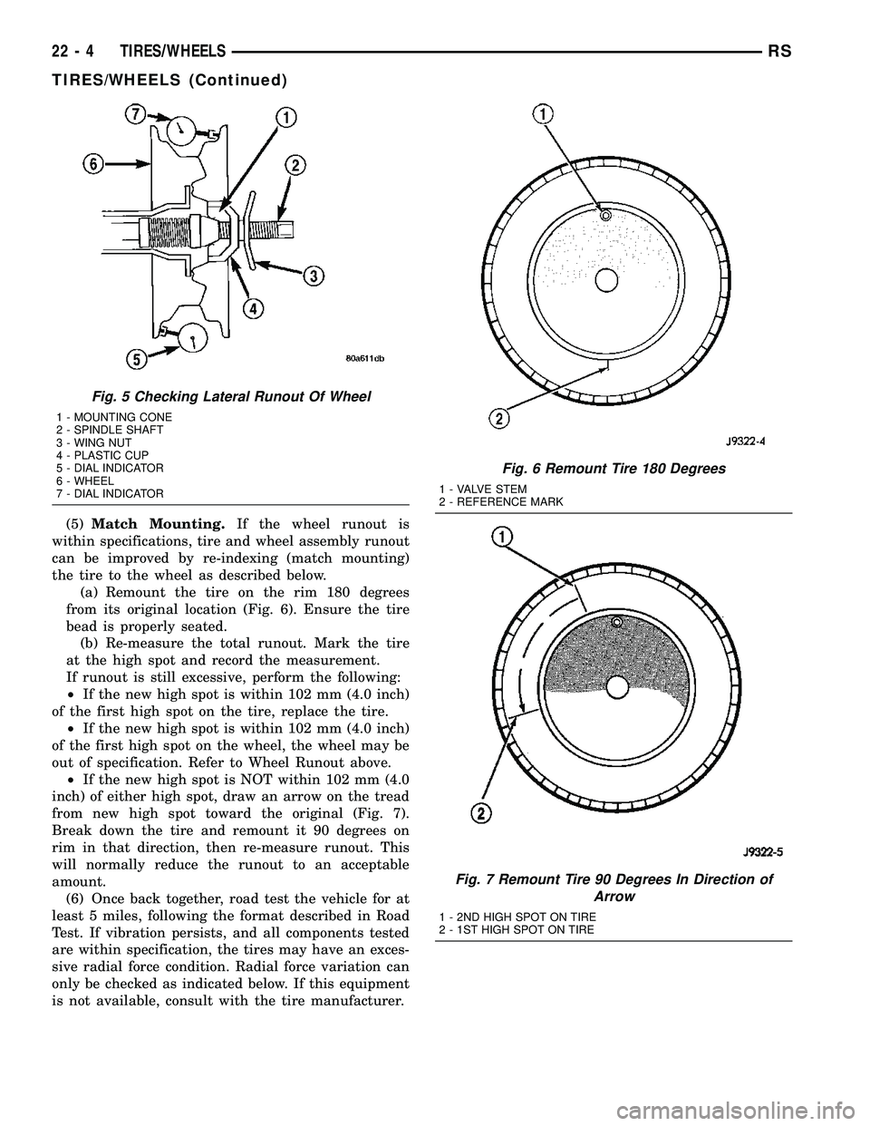
(a) Remount the tire on the rim 180 degrees
from its original location (Fig. 6). Ensure the tire
bead is properly seated.
(b) Re-measure the total runout. Mark the tire
at the high spot and record the measurement.
If runout is still excessive, perform the following:
²If the new high spot is within 102 mm (4.0 inch)
of the first high spot on the tire, replace the tire.
²If the new high spot is within 102 mm (4.0 inch)
of the first high spot on the wheel, the wheel may be
out of specification. Refer to Wheel Runout above.
²If the new high spot is NOT within 102 mm (4.0
inch) of either high spot, draw an arrow on the tread
from new high spot toward the original (Fig. 7).
Break down the tire and remount it 90 degrees on
rim in that direction, then re-measure runout. This
will normally reduce the runout to an acceptable
amount.
(6) Once back together, road test the vehicle for at
least 5 miles, following the format described in Road
Test. If vibration persists, and all components tested
are within specification, the tires may have an exces-
sive radial force condition. Radial force variation can
only be checked as indicated below. If this equipment
is not available, consult with the tire manufacturer.
Fig. 5 Checking Lateral Runout Of Wheel
1 - MOUNTING CONE
2 - SPINDLE SHAFT
3 - WING NUT
4 - PLASTIC CUP
5 - DIAL INDICATOR
6 - WHEEL
7 - DIAL INDICATOR
Fig. 6 Remount Tire 180 Degrees
1 - VALVE STEM
2 - REFERENCE MARK
Fig. 7 Remount Tire 90 Degrees In Direction of
Arrow
1 - 2ND HIGH SPOT ON TIRE
2 - 1ST HIGH SPOT ON TIRE
22 - 4 TIRES/WHEELSRS
TIRES/WHEELS (Continued)
Page 1762 of 2339
RADIAL FORCE VARIATION
Radial Force Variation can be checked using the
Hunter GSP 9700 Vibration Control System (Wheel
Balancer) or equivalent, if available. This type of
equipment helps to correct ride disturbances by
reducing the radial force variation of an assembly
through re-indexing of the tire to wheel.
The equipment manufacturer or DaimlerChrysler
Corporation may supply reference values as guide-
lines. Radial force measurements above the reference
value may not always result in a ride disturbance,
nor do they automatically mean the assembly compo-
nents are out of specification. Do not replace compo-
nents based on radial force values alone. Balancing,
runout diagnosis, re-indexing, and subjective road
testing must be performed as outlined in previous
sections of this diagnosis and testing procedure.
Use the Radial Force equipment to identify suspect
assemblies and minimize the radial forces. After all
suspect assemblies are optimized, reinstall the
assemblies and road test the vehicle. If a disturbance
still exists and all other vibration diagnostic proce-
dures have been completed, replace one tire or one
wheel at a time, starting with the assembly having
the highest force variation. Be sure to minimize each
new assembly. Road test the vehicle following each
replacement. Continue this process until the distur-
bance is resolved.
NOTE: When using Radial Force equipment, it is
critically important to set proper tire inflation pres-
sure and ensure centering of the wheel on the
equipment spindle.
RADIAL FORCE VARIATION REFERENCE
VALUES
DESCRIPTION SPECIFICATION
Total Radial Force
Variation (RFV)Less Than 22 Lbs. 2
Lbs.
Radial First Harmonic
(R1H)Less Than 16 Lbs. 2
Lbs.
Radial Second Harmonic
(R2H)Less Than 12 Lbs. 2
Lbs.
STANDARD PROCEDURE
STANDARD PROCEDURE - TIRE AND WHEEL
BALANCE
NOTE: Balance equipment must be calibrated and
maintained per equipment manufacturer's specifica-
tions.
Wheel balancing can be accomplished with either
on-vehicle or off-vehicle equipment.
NOTE: If using on-vehicle balancing equipment, on
the driving axle, remove the opposite wheel and tire
assembly.
It is recommended that a two-plane dynamic bal-
ancer be used when a wheel and tire assembly
requires balancing. A static balancer should only be
used when a two-plane balancer is not available.
Balance wheel and tire assemblies dynamically and
statically to less than 0.25 (
1¤4) ounce.
For static balancing, find location of heavy spot
causing imbalance. Counter balance wheel directly
opposite the heavy spot. Determine weight required
to counterbalance the area of imbalance. Place half of
this weight on theinnerrim flange and the other
half on theouterrim flange (Fig. 8).
For dynamic balancing, the balance equipment is
designed to indicate the location and amount of
weight to be applied to both the inner and outer rim
flanges (Fig. 9).
The aluminum wheels on this vehicle use a unique
wheel weight (Fig. 10). This wheel weight is designed
to fit the contoured surface of the wheel (Fig. 10).
When balancing an aluminum wheel, this wheel
weight must be used. Do not use any other type of
wheel weight. It will not properly fit the contour of
the wheel.
Always verify the Balance. When using off-vehicle
equipment, rotate assembly 180 degrees on balance
equipment to verify balance. Variation should not be
more than 0.125 (
1¤8) ounce. If variation is more than
0.125 ounce, balancing equipment could be malfunc-
tioning.
RSTIRES/WHEELS22-5
TIRES/WHEELS (Continued)
Page 1766 of 2339
(3) Place the wheel cover on the wheel in the fol-
lowing fashion:
(a) Align the valve notch in the wheel cover with
the valve stem on the wheel.
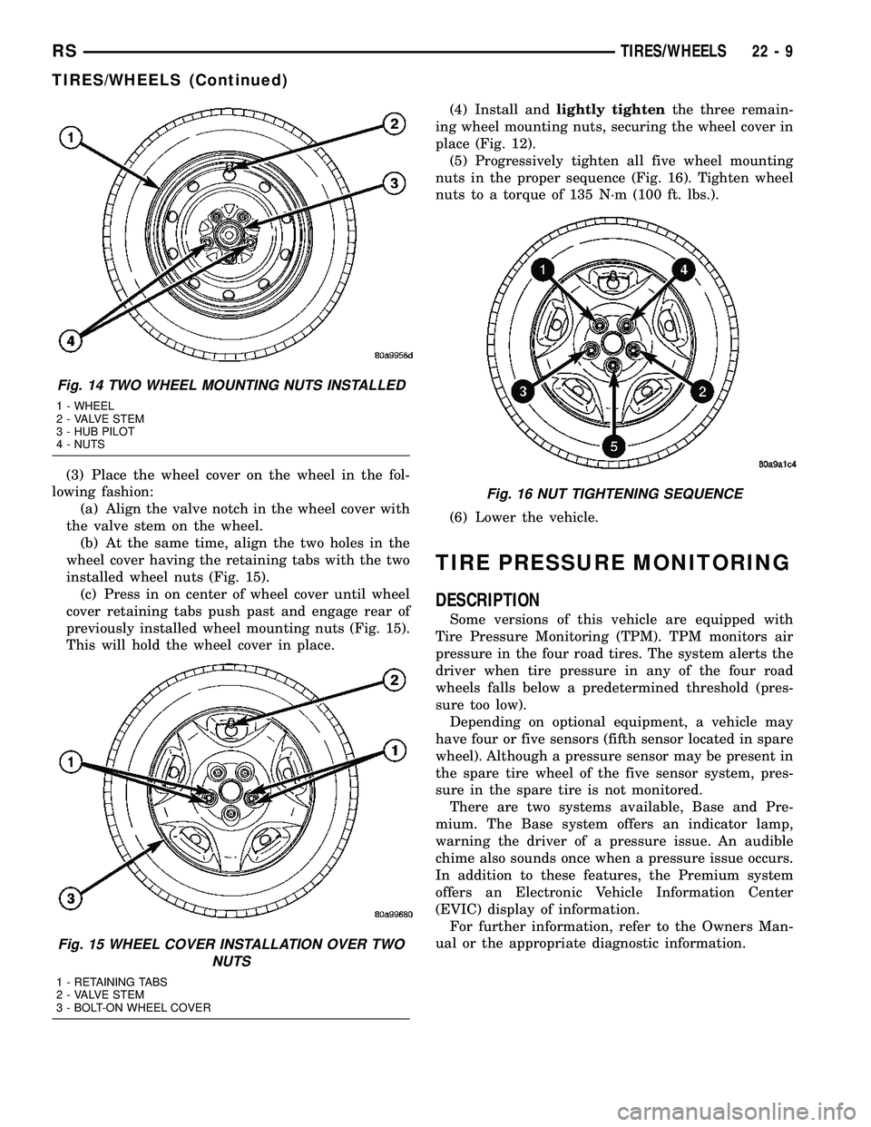
(b) At the same time, align the two holes in the
wheel cover having the retaining tabs with the two
installed wheel nuts (Fig. 15).
(c) Press in on center of wheel cover until wheel
cover retaining tabs push past and engage rear of
previously installed wheel mounting nuts (Fig. 15).
This will hold the wheel cover in place.(4) Install andlightly tightenthe three remain-
ing wheel mounting nuts, securing the wheel cover in
place (Fig. 12).
(5) Progressively tighten all five wheel mounting
nuts in the proper sequence (Fig. 16). Tighten wheel
nuts to a torque of 135 N´m (100 ft. lbs.).
(6) Lower the vehicle.
TIRE PRESSURE MONITORING
DESCRIPTION
Some versions of this vehicle are equipped with
Tire Pressure Monitoring (TPM). TPM monitors air
pressure in the four road tires. The system alerts the
driver when tire pressure in any of the four road
wheels falls below a predetermined threshold (pres-
sure too low).
Depending on optional equipment, a vehicle may
have four or five sensors (fifth sensor located in spare
wheel). Although a pressure sensor may be present in
the spare tire wheel of the five sensor system, pres-
sure in the spare tire is not monitored.
There are two systems available, Base and Pre-
mium. The Base system offers an indicator lamp,
warning the driver of a pressure issue. An audible
chime also sounds once when a pressure issue occurs.
In addition to these features, the Premium system
offers an Electronic Vehicle Information Center
(EVIC) display of information.
For further information, refer to the Owners Man-
ual or the appropriate diagnostic information.
Fig. 14 TWO WHEEL MOUNTING NUTS INSTALLED
1 - WHEEL
2 - VALVE STEM
3 - HUB PILOT
4 - NUTS
Fig. 15 WHEEL COVER INSTALLATION OVER TWO
NUTS
1 - RETAINING TABS
2 - VALVE STEM
3 - BOLT-ON WHEEL COVER
Fig. 16 NUT TIGHTENING SEQUENCE
RSTIRES/WHEELS22-9
TIRES/WHEELS (Continued)
Page 1767 of 2339
OPERATION
The Tire Pressure Monitoring (TPM) system uses
radio and sensor technology to monitor tire air pres-
sure levels. Sensors, mounted to each road wheel as
part of the valve stem, transmit a low frequency indi-
cating their individual pressure to a receiver located
in the Wireless Control Module (WCM) portion of the
Sentry Key Remote Electronic Entry Module
(SKREEM). These transmissions occur approximately
once every minute at speeds over 20 mph (32 km/h).
The Tire Pressure Monitoring system remains active
even if no tire pressure related message is displayed.
The sensors lay dormant (Park Mode), then wake
and start transmitting (Drive Mode) when the vehicle
first reaches speeds over 20 mph (32 km/h). Once the
wheels stop rotating for a period of approximately 30
minutes, the sensors shut down until again awaken.
Although not transmitting as when in Drive Mode,
while in Park Mode, the sensors still transmit
approximately once every 13 hours to let the receiver
know air pressure status at that time.
The receiver only receives information from the
four rotating tires. A fifth sensor may be located in
the spare tire wheel, depending on vehicle options.
Although this fifth sensor may be present, it does not
broadcast any information because it does not rotate.
When the system detects that a tire is going low,
below the Low Pressure (lamp) ON Threshold (See
following table), the driver is alerted to the situation.
The Base system illuminates an indicator lamp,
warning the driver of a pressure issue and sounds an
audible chime. In equipped with the Premium sys-
tem, the information is also displayed on the Elec-
tronic Vehicle Information Center (EVIC).
Once pressure in the suspect tire raises above the
Low Pressure (lamp) OFF Threshold, the lamp will
go out and the system returns to normal.
TPM THRESHOLD PRESSURES
DESCRIPTION SPECIFICATION
Placard Pressure (Cold) 36 PSI (248 kPa)
Low Pressure OFF Threshold 33 PSI (228 kPa)
Low Pressure ON Threshold 28 PSI (193 kPa)
SENSOR - TPM
DESCRIPTION
On vehicles equipped with Tire Pressure Monitor-
ing, one tire pressure sensor is mounted to each road
wheel (Fig. 18), and depending on factory wheel
options, a sensor may be located in the spare tire
wheel. Both aluminum and steel wheels are used in
this system, although sensors for one type wheel can-
not be used in the other type wheel.Each sensor has an internal battery that lasts up
to 10 years. The battery is not serviceable. At the
time of battery failure, the sensor must be replaced.
The serviceable components of the tire pressure sen-
sor are:
²Sensor-To-Wheel Grommet
²Valve Stem Cap
²Valve Stem Core
Valve stem caps and cores are specifically designed
for the tire pressure monitoring sensors. Although
similar to standard valve stem caps and cores, they
are different.
CAUTION: Do not use a standard valve stem cap or
core in a tire pressure sensor. Always use the orig-
inal equipment style sensor cap and core.
CAUTION: Do not reuse the Sensor-To-Wheel Grom-
met. Always use a new grommet when installing a
pressure sensor and properly torque the sensor
nut.
CAUTION: Do not attempt to install a tire pressure
sensor in an aftermarket wheel. Use only in original
style factory wheels.
OPERATION
The battery operated tire pressure sensors lay dor-
mant (Park Mode), then wake and start transmitting
(Drive Mode) when the vehicle first reaches speeds
over 20 mph (32 km/h). Once the wheels stop rotat-
ing for a period of approximately 30 minutes, the
sensors shut down until again awaken. Although not
transmitting as when in Drive Mode, while in Park
Mode, the sensors still transmit approximately once
every 13 hours to let the receiver know air pressure
status at that time.
Each sensor transmits tire pressure data approxi-
mately once every minute. Each sensor's (transmit-
ter) broadcast is uniquely coded so that the wireless
control module (WCM) can monitor the state of each
of the sensors on the four rotating road wheels. The
WCM (located in the SKREEM) automatically learns
and stores the sensor's ID while driving after a sen-
sor has been replaced. There is no retraining neces-
sary.
The receiver only receives information from the
four rotating tires. A fifth sensor may be located in
the spare tire wheel, depending on vehicle options.
Although this fifth sensor may be present, it does not
broadcast any information because it does not rotate.
For additional information, refer to Appropriate
Diagnostic Information.
22 - 10 TIRES/WHEELSRS
TIRE PRESSURE MONITORING (Continued)
Page 1771 of 2339
Radial-ply tires must always be used in sets of four
and under no circumstances should they be used on
the front only. It is recommended that tires from dif-
ferent manufacturers NOT be mixed. They may be
mixed with a temporary spare tire when necessary. A
maximum speed of 80 km/h (50 mph) is recom-
mended while a temporary spare is in use.
Radial-ply tires have the same load-carrying capac-
ity as other types of tires of the same size. They also
use the same recommended inflation pressures.
DESCRIPTION - REPLACEMENT TIRES
WARNING: FAILURE TO EQUIP THE VEHICLE WITH
TIRES HAVING ADEQUATE SPEED CAPABILITY
CAN RESULT IN SUDDEN TIRE FAILURE.
WARNING: IN ORDER TO MAINTAIN THE SPEED
CAPABILITY OF THE VEHICLE, REPLACEMENT
TIRES MUST HAVE SPEED RATINGS EQUAL TO OR
HIGHER THAN THOSE FITTED TO THE VEHICLE AS
ORIGINAL EQUIPMENT. IF TIRES WITH LOWER
SPEED RATINGS ARE FITTED, THE VEHICLE'S
HANDLING MAY BE AFFECTED AND THE SPEED
CAPABILITY OF THE VEHICLE MAY BE LOWERED
TO THE MAXIMUM SPEED CAPABILITY OF THE
REPLACEMENT TIRES. TO AVOID AN ACCIDENT
RESULTING IN SEVERE OR FATAL INJURY, CON-
SULT THE TIRE MANUFACTURER IN REGARDS TO
MAXIMUM SPEED RATINGS.
It is recommended that tires equivalent to the orig-
inal equipment tires be used when replacement is
needed.
Failure to use equivalent replacement tires may
adversely affect the safety and handling of the vehi-
cle.
The original equipment tires provide a proper com-
bination of many characteristics such as:
²Ride
²Noise
²Handling
²Durability
²Tread life²Traction
²Rolling resistance
²Speed capability
The use of tires smaller than the minimum tire
size approved for the vehicle can result in tire over-
loading and failure.
Use tires that have the approved load rating for
the vehicle and never overload them. Failure to equip
the vehicle with tires having adequate speed capabil-
ity can result in sudden tire failure and loss of vehi-
cle control.
The use of oversize tires may cause interference
with vehicle components. Under extremes of suspen-
sion and steering travel, interference with vehicle
components may cause tire damage.
DESCRIPTION - SPARE TIRE (TEMPORARY)
The temporary (convenience) spare tire is designed
for emergency use only. The original tire should be
repaired and reinstalled, or replaced with a new, at
the first opportunity.
The temporary (convenience) spare tire should be
inflated to the pressure listed on its sidewall. Do not
exceed speeds of 80 km/h (50 mph) when the tempo-
rary spare tire is in use on the vehicle. Refer to the
Owner's Manual for more details.
DIAGNOSIS AND TESTING
DIAGNOSIS AND TESTING - TIRE NOISE
Unusual tire noise can be associated with tire and
wheel vibration or irregular tire wear. For vibration,
(Refer to 22 - TIRES/WHEELS - DIAGNOSIS AND
TESTING). For irregular tire wear, (Refer to 22 -
TIRES/WHEELS/TIRES - DIAGNOSIS AND TEST-
ING).
DIAGNOSIS AND TESTING - TIRE/VEHICLE
LEAD
Use the following Vehicle Lead Diagnosis And Cor-
rection Chart to diagnose and correct a vehicle lead
or drift problem.
22 - 14 TIRES/WHEELSRS
TIRES (Continued)
Page 1774 of 2339
Inflation pressures specified on the Tire Inflation
Pressure Label are always the cold inflation pressure
of the tire. Cold inflation pressure is obtained after
the vehicle has not been operated for at least 3
hours, or the vehicle is driven less than one mile
after being inoperative for 3 hours. Tire inflation
pressures may increase from 2 to 6 pounds per
square inch (psi) (14 to 41 kPa) during operation. Do
not reduce this normal pressure buildup.
Improper inflation can cause:
²Uneven wear patterns
²Reduced tread life
²Reduced fuel economy
²Unsatisfactory ride
²The vehicle to drift.
WARNING: OVER OR UNDER INFLATED TIRES CAN
AFFECT VEHICLE HANDLING. THE TIRE CAN FAIL
SUDDENLY, RESULTING IN LOSS OF VEHICLE
CONTROL.
Under inflation causes rapid shoulder wear, tire
flexing, and can result in tire failure (Fig. 24).
Over inflation causes rapid center wear and loss of
the tire's ability to cushion shocks (Fig. 25).
STANDARD PROCEDURE - TIRE PRESSURE
FOR HIGH SPEED OPERATION
DaimlerChrysler Corporation advocates driving at
safe speeds within posted speed limits. Where speed
limits allow the vehicle to be driven at high speeds,
correct tire inflation pressure is very important.
Vehicles loaded to maximum capacity should not be
driven at continuous speeds over 120 km/h (75 mph).
Never exceed the maximum speed capacity of the
tire. For information on tire identification and speed
ratings, (Refer to 22 - TIRES/WHEELS/TIRES -
DESCRIPTION).
STANDARD PROCEDURE - TIRE LEAK
REPAIRING
For proper repairing, a radial tire must be removed
from the wheel. Repairs should only be made if the
defect, or puncture, is in the tread area (Fig. 26). The
tire should be replaced if the puncture is located in
the sidewall.
Deflate tire completely before attempting to dis-
mount the tire from the wheel.Use a lubricant
such as a mild soap solution when dismounting
or mounting tire.Use tools free of burrs or sharp
edges which could damage the tire or wheel rim.
Before mounting tire on wheel, make sure all rust
is removed from the rim bead and repaint if neces-
sary.
Install wheel on vehicle, and progressively tighten
the 5 wheel nuts to a torque of 135 N´m (100 ft. lbs.).
Fig. 24 Under Inflation Wear
1 - THIN TIRE TREAD AREAS
Fig. 25 Over Inflation Wear
1 - THIN TIRE TREAD AREA
RSTIRES/WHEELS22-17
TIRES (Continued)
Page 1776 of 2339
DIAGNOSIS AND TESTING - WHEEL
INSPECTION
Inspect wheels for:
²Excessive runout
²Dents, cracks or irregular bends
²Damaged wheel stud (lug) holes
²Air Leaks
NOTE: Do not attempt to repair a wheel by hammer-
ing, heating or welding.
If a wheel is damaged, an original equipment
replacement wheel should be used. When obtaining
replacement wheels, they must be equivalent in load
carrying capacity. The diameter, width, offset, pilot
hole and bolt circle of the wheel should be the same
as the original wheel.
WARNING: FAILURE TO USE EQUIVALENT
REPLACEMENT WHEELS MAY ADVERSELY
AFFECT THE SAFETY AND HANDLING OF THE
VEHICLE.
WARNING: REPLACEMENT WITH USED WHEELS IS
NOT RECOMMENDED. THE SERVICE HISTORY OF
THE WHEEL MAY HAVE INCLUDED SEVERE TREAT-
MENT OR VERY HIGH MILEAGE. THE RIM COULD
FAIL WITHOUT WARNING.
CLEANING
WHEEL AND WHEEL TRIM CARE
All wheels and wheel trim, especially aluminum
and chrome plated, should be cleaned regularly using
mild soap and water to maintain their luster and to
prevent corrosion. Wash them with the same soap
solution recommended for the body of the vehicle.
When cleaning extremely dirty wheels, care must
be taken in the selection of tire and wheel cleaning
chemicals and equipment to prevent damage to the
wheels. MopartWheel Treatment or MopartChrome
Cleaner is recommended. Any of the ªDO NOT USEº
items listed below can damage wheels and wheel
trim.DO NOT USE:
²Any abrasive cleaner
²Any abrasive cleaning pad (such as steel wool)
or abrasive brush
²Any cleaner that contains an acid which can
react with and discolor the chrome surface.Many
wheel cleaners contain acids that can harm the
wheel surface.
²Oven cleaner
²A car wash that uses carbide-tipped wheel clean-
ing brushes or acidic solutions.
SPECIFICATIONS
WHEEL
SPECIFICATIONS
DESCRIPTION SPECIFICATION
Wheel Mounting (Lug)
Nut Hex Size19 mm
Wheel Mounting Stud
SizeM12 x 1.5 mm
TORQUE SPECIFICATIONS
DESCRIPTION N´mFt.
Lbs.In.
Lbs.
TPM Sensor Mounting Nut 4 Ð 35
Wheel Mounting (Lug ) Nut 135 100 Ð
WHEEL COVER
DESCRIPTION
This vehicle uses a bolt-on type wheel cover (Fig.
29).
This bolt-on wheel cover cannot be removed from
the wheel until three of the five wheel mounting nuts
shown are removed (Fig. 29). The bolt-on wheel cover
can then be removed with the remaining two wheel
nuts tightened in place.
REMOVAL
(1) Noting the location of the valve stem in rela-
tionship to the wheel mounting nuts, remove the
three wheel mounting nuts securing the wheel cover
to the wheel and hub (Fig. 29).
CAUTION: When removing the wheel cover, do not
pry the wheel cover from the wheel. This can result
in damage to the wheel cover. The wheel cover is
removed by pulling it off the wheel by hand.
RSTIRES/WHEELS22-19
WHEELS (Continued)