Page 1477 of 2339
(17) Remove oil pump assembly (Fig. 30) (Fig. 31). (18) Remove oil pump gasket (Fig. 32).
CAUTION: If transaxle failure has occurred, the
cooler bypass valve must be replaced. Do not
re-use or attempt to clean valve.
(19) Remove cooler bypass valve (Fig. 33).
Fig. 30 Remove Oil Pump
1 - ªPUSH INº ON INPUT SHAFT WHILE REMOVING PUMP
Fig. 31 Oil Pump Removed
1 - OIL PUMP
2 - GASKET
Fig. 32 Remove Oil Pump Gasket
1 - PUMP GASKET
Fig. 33 Remove Bypass Valve
1 - COOLER BYPASS VALVE
21 - 16 40TE AUTOMATIC TRANSAXLERS
40TE AUTOMATIC TRANSAXLE (Continued)
Page 1490 of 2339
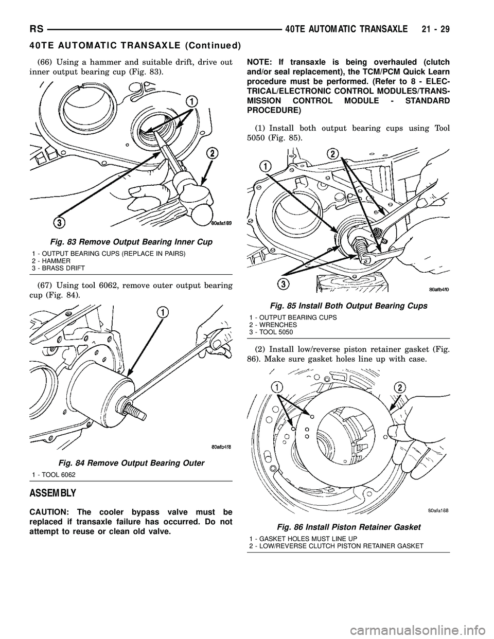
(66) Using a hammer and suitable drift, drive out
inner output bearing cup (Fig. 83).
(67) Using tool 6062, remove outer output bearing
cup (Fig. 84).
ASSEMBLY
CAUTION: The cooler bypass valve must be
replaced if transaxle failure has occurred. Do not
attempt to reuse or clean old valve.NOTE: If transaxle is being overhauled (clutch
and/or seal replacement), the TCM/PCM Quick Learn
procedure must be performed. (Refer to 8 - ELEC-
TRICAL/ELECTRONIC CONTROL MODULES/TRANS-
MISSION CONTROL MODULE - STANDARD
PROCEDURE)
(1) Install both output bearing cups using Tool
5050 (Fig. 85).
(2) Install low/reverse piston retainer gasket (Fig.
86). Make sure gasket holes line up with case.
Fig. 83 Remove Output Bearing Inner Cup
1 - OUTPUT BEARING CUPS (REPLACE IN PAIRS)
2 - HAMMER
3 - BRASS DRIFT
Fig. 84 Remove Output Bearing Outer
1 - TOOL 6062
Fig. 85 Install Both Output Bearing Cups
1 - OUTPUT BEARING CUPS
2 - WRENCHES
3 - TOOL 5050
Fig. 86 Install Piston Retainer Gasket
1 - GASKET HOLES MUST LINE UP
2 - LOW/REVERSE CLUTCH PISTON RETAINER GASKET
RS40TE AUTOMATIC TRANSAXLE21-29
40TE AUTOMATIC TRANSAXLE (Continued)
Page 1508 of 2339
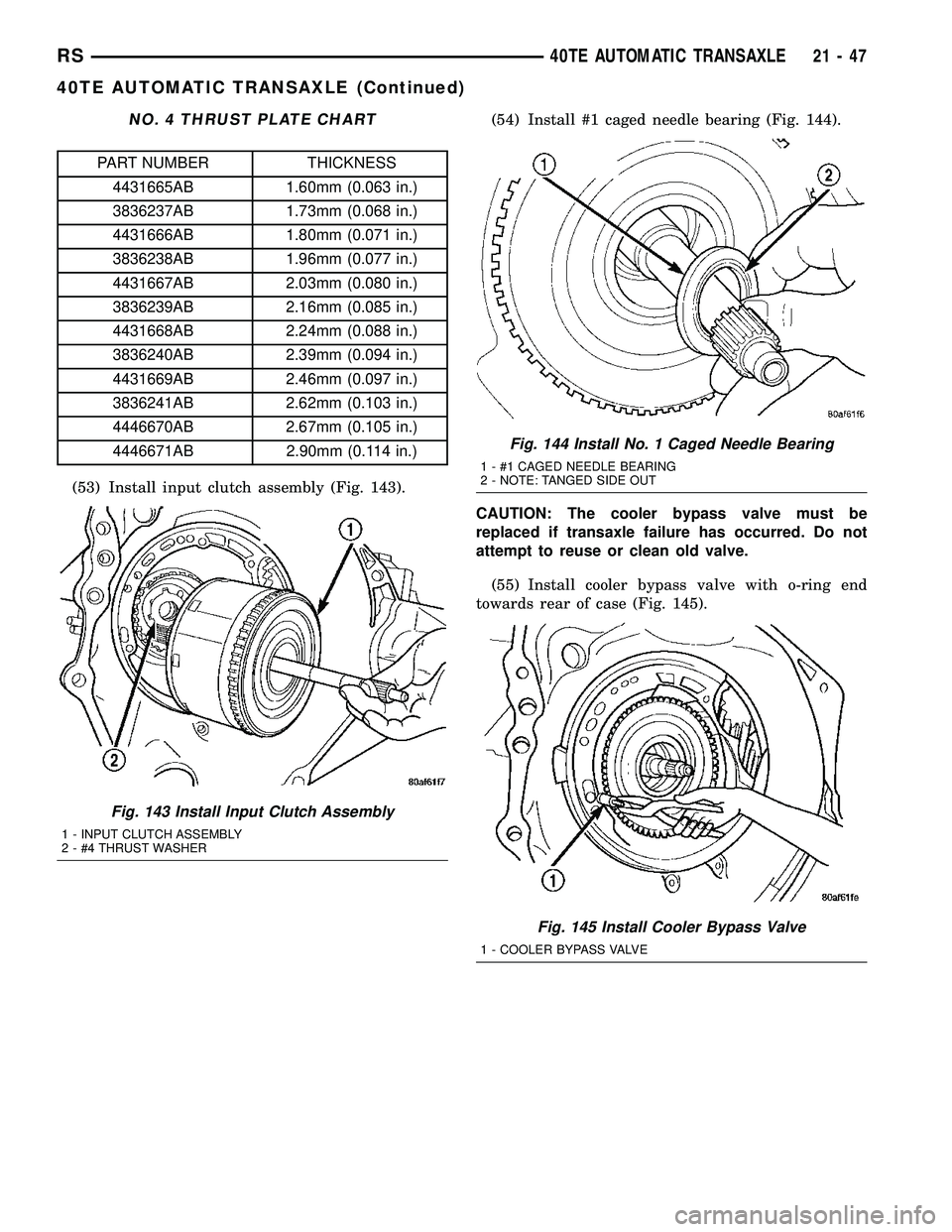
NO. 4 THRUST PLATE CHART
PART NUMBER THICKNESS
4431665AB 1.60mm (0.063 in.)
3836237AB 1.73mm (0.068 in.)
4431666AB 1.80mm (0.071 in.)
3836238AB 1.96mm (0.077 in.)
4431667AB 2.03mm (0.080 in.)
3836239AB 2.16mm (0.085 in.)
4431668AB 2.24mm (0.088 in.)
3836240AB 2.39mm (0.094 in.)
4431669AB 2.46mm (0.097 in.)
3836241AB 2.62mm (0.103 in.)
4446670AB 2.67mm (0.105 in.)
4446671AB 2.90mm (0.114 in.)
(53) Install input clutch assembly (Fig. 143).(54) Install #1 caged needle bearing (Fig. 144).
CAUTION: The cooler bypass valve must be
replaced if transaxle failure has occurred. Do not
attempt to reuse or clean old valve.
(55) Install cooler bypass valve with o-ring end
towards rear of case (Fig. 145).
Fig. 143 Install Input Clutch Assembly
1 - INPUT CLUTCH ASSEMBLY
2 - #4 THRUST WASHER
Fig. 144 Install No. 1 Caged Needle Bearing
1 - #1 CAGED NEEDLE BEARING
2 - NOTE: TANGED SIDE OUT
Fig. 145 Install Cooler Bypass Valve
1 - COOLER BYPASS VALVE
RS40TE AUTOMATIC TRANSAXLE21-47
40TE AUTOMATIC TRANSAXLE (Continued)
Page 1512 of 2339
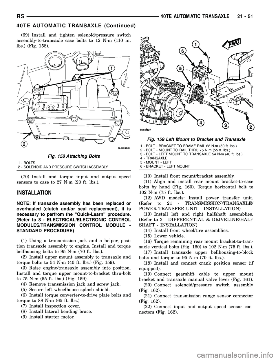
(69) Install and tighten solenoid/pressure switch
assembly-to-transaxle case bolts to 12 N´m (110 in.
lbs.) (Fig. 158).
(70) Install and torque input and output speed
sensors to case to 27 N´m (20 ft. lbs.).
INSTALLATION
NOTE: If transaxle assembly has been replaced or
overhauled (clutch and/or seal replacement), it is
necessary to perfrom the ªQuick-Learnº procedure.
(Refer to 8 - ELECTRICAL/ELECTRONIC CONTROL
MODULES/TRANSMISSION CONTROL MODULE -
STANDARD PROCEDURE)
(1) Using a transmission jack and a helper, posi-
tion transaxle assembly to engine. Install and torque
bellhousing bolts to 95 N´m (70 ft. lbs.).
(2) Install upper mount assembly to transaxle and
torque bolts to 54 N´m (40 ft. lbs.) (Fig. 159).
(3) Raise engine/transaxle assembly into position.
Install and torque upper mount-to-bracket thru-bolt
to 75 N´m (55 ft. lbs.) (Fig. 159).
(4) Remove transmission jack and screw jack.
(5) Secure left wheelhouse splash shield.
(6) Install torque converter-to-drive plate bolts and
torque to 88 N´m (65 ft. lbs.)
(7) Install inspection cover.
(8) Install lateral bending brace.
(9) Install starter motor.(10) Install front mount/bracket assembly.
(11) Align and install rear mount bracket-to-case
bolts by hand (Fig. 160). Torque horizontal bolt to
102 N´m (75 ft. lbs.).
(12) AWD models: Install power transfer unit.
(Refer to 21 - TRANSMISSION/TRANSAXLE/
POWER TRANSFER UNIT - INSTALLATION)
(13) Install left and right halfshaft assemblies.
(Refer to 3 - DIFFERENTIAL & DRIVELINE/HALF
SHAFT - INSTALLATION)
(14) Install front wheel/tire assemblies.
(15) Lower vehicle.
(16) Torque remaining rear mount bracket-to-tran-
saxle vertical bolts (Fig. 160) to 102 N´m (75 ft. lbs.).
(17) Install transaxle upper bellhousing-to-block
bolts and torque to 95 N´m (70 ft. lbs.).
(18) Install and connect crank position sensor (if
equipped).
(19) Connect gearshift cable to upper mount
bracket and transaxle manual valve lever (Fig. 161).
(20) Connect solenoid/pressure switch assembly
(Fig. 162).
(21) Connect transmission range sensor connector
(Fig. 162).
(22) Connect input and output speed sensor con-
nectors (Fig. 162).
Fig. 158 Attaching Bolts
1 - BOLTS
2 - SOLENOID AND PRESSURE SWITCH ASSEMBLY
Fig. 159 Left Mount to Bracket and Transaxle
1 - BOLT - BRACKET TO FRAME RAIL 68 N´m (50 ft. lbs.)
2 - BOLT - MOUNT TO RAIL THRU 75 N´m (55 ft. lbs.)
3 - BOLT - LEFT MOUNT TO TRANSAXLE 54 N´m (40 ft. lbs.)
4 - TRANSAXLE
5 - MOUNT - LEFT
6 - BRACKET - LEFT MOUNT
RS40TE AUTOMATIC TRANSAXLE21-51
40TE AUTOMATIC TRANSAXLE (Continued)
Page 1514 of 2339
(23) Remove plugs and connect transaxle oil cooler
lines. (Refer to 7 - COOLING/TRANSMISSION -
STANDARD PROCEDURE)
(24) Remove plug and Install fluid level indicator/
tube assembly.
(25) Install coolant recovery bottle (Fig. 163).
(26) Install battery shield.
(27) Connect battery cables.
(28) Fill transaxle with suitable amount of ATF+4
(Automatic Transmission FluidÐType 9602). (Refer
to 21 - TRANSMISSION/TRANSAXLE/AUTOMATIC
- 41TE/FLUID - STANDARD PROCEDURE)
Fig. 163 Coolant Recovery Bottle
1 - COOLANT RECOVERY CONTAINER
2 - HOSE
3 - BOLT
4 - SUB FRAME RAIL
RS40TE AUTOMATIC TRANSAXLE21-53
40TE AUTOMATIC TRANSAXLE (Continued)
Page 1536 of 2339
OPERATION
The differential assembly is driven by the transfer
shaft by way of the differential ring gear. The ring
gear drives the differential case, and the case drives
the driveshafts through the differential gears. The
differential pinion and side gears are supported in
the case by thrust washers and a pinion shaft. Dif-
ferential pinion and side gears make it possible for
front tires to rotate at different speeds while corner-
ing.
DISASSEMBLY
NOTE: The differential is serviced as an assembly.
The only parts that are serviceable within the differ-
ential are the differential bearing cups and cones. If
any other part fails within the differential, you must
replace the differential assembly along with the
transfer shaft.
The transfer shaft should be removed for differen-
tial repair and bearing turning torque checking.
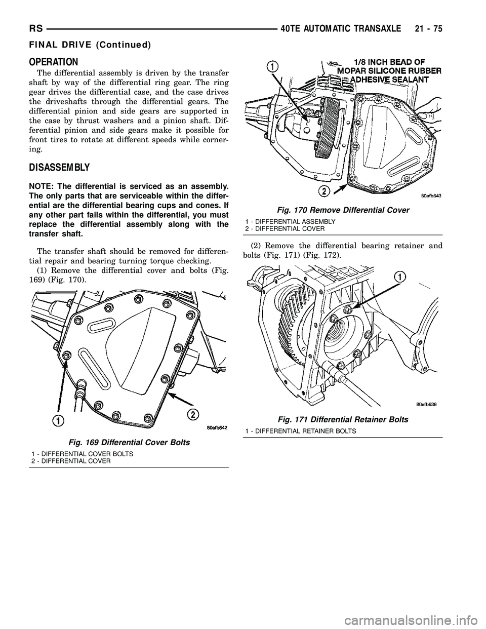
(1) Remove the differential cover and bolts (Fig.
169) (Fig. 170).(2) Remove the differential bearing retainer and
bolts (Fig. 171) (Fig. 172).
Fig. 169 Differential Cover Bolts
1 - DIFFERENTIAL COVER BOLTS
2 - DIFFERENTIAL COVER
Fig. 170 Remove Differential Cover
1 - DIFFERENTIAL ASSEMBLY
2 - DIFFERENTIAL COVER
Fig. 171 Differential Retainer Bolts
1 - DIFFERENTIAL RETAINER BOLTS
RS40TE AUTOMATIC TRANSAXLE21-75
FINAL DRIVE (Continued)
Page 1539 of 2339
DIFFERENTIAL SERVICE TOOLS
COMPONENT REMOVER INSTALLER
Diff. Bear. On
Retainer Side5048, 5048-4
Collets,
L-4539-2
Button5052, C-4171
Diff. Bear. On
Ext. Hous. Side5048, 5048-3
Collets,
L-4539-2
ButtonL-4410, C-4171
Diff. Race. On
Retainer Side6062-A 6061, C-4171
Diff. Race. On
Ext. Hous. SideL-4518 L-4520, C-4171
Extension
Housing Seal7794-A, C-637
Slide HammerL-4520, C-4171
Bearing
Retainer Seal794-A, C-637
Slide HammerL-4520, C-4171
ASSEMBLY
NOTE: The differential is serviced as an assembly.
The only parts that are serviceable within the differ-
ential are the differential bearing cups and cones. If
any other part fails within the differential, you must
replace the differential assembly along with the
transfer shaft.
NOTE: Use MoparTATF RTV (MS-GF41), or equiva-
lent, on retainer and extension housing/adapter
plate to seal to case.
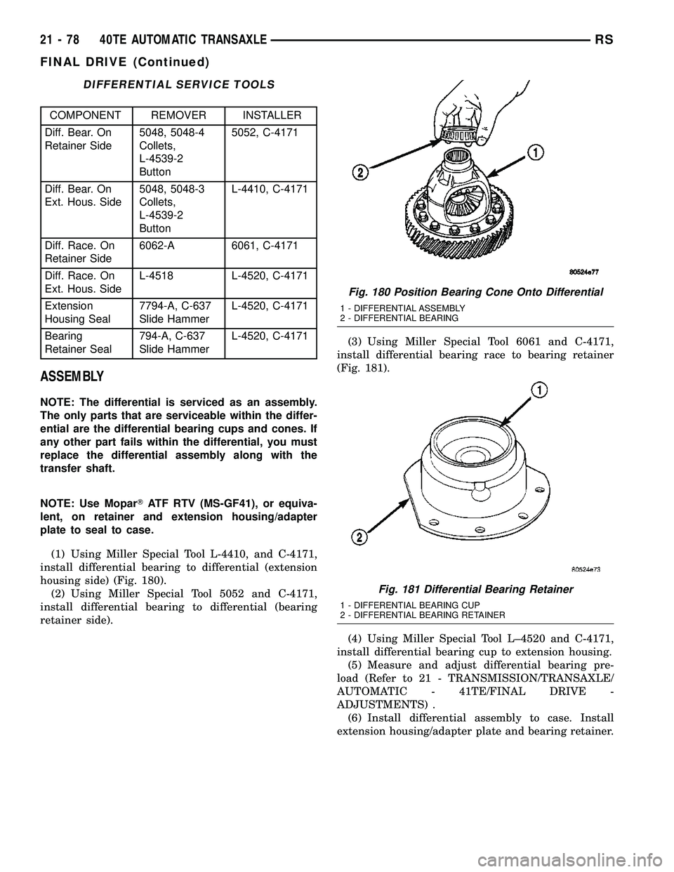
(1) Using Miller Special Tool L-4410, and C-4171,
install differential bearing to differential (extension
housing side) (Fig. 180).
(2) Using Miller Special Tool 5052 and C-4171,
install differential bearing to differential (bearing
retainer side).(3) Using Miller Special Tool 6061 and C-4171,
install differential bearing race to bearing retainer
(Fig. 181).
(4) Using Miller Special Tool L±4520 and C-4171,
install differential bearing cup to extension housing.
(5) Measure and adjust differential bearing pre-
load (Refer to 21 - TRANSMISSION/TRANSAXLE/
AUTOMATIC - 41TE/FINAL DRIVE -
ADJUSTMENTS) .
(6) Install differential assembly to case. Install
extension housing/adapter plate and bearing retainer.
Fig. 180 Position Bearing Cone Onto Differential
1 - DIFFERENTIAL ASSEMBLY
2 - DIFFERENTIAL BEARING
Fig. 181 Differential Bearing Retainer
1 - DIFFERENTIAL BEARING CUP
2 - DIFFERENTIAL BEARING RETAINER
21 - 78 40TE AUTOMATIC TRANSAXLERS
FINAL DRIVE (Continued)
Page 1576 of 2339
A conventional mechanical interlock system is also
used. This system manually prohibits shifter move-
ment when the ignition switch is in the LOCK or
ACC positions. Solenoid operation is not required in
these key positions.
For intended BTSI system operation, refer to the
following chart:
ACTION EXPECTED RESPONSE
1. Turn key to the9OFF9
position.1. Shifter CAN be shifted
out of park with brake
pedal applied.
2. Turn key to the
9ON/RUN9position.2. Shifter CANNOT be
shifted out of park.
3. Turn key to the
9ON/RUN9position and
depress the brake pedal.3. Shifter CAN be shifted
out of park.
4. Leave shifter in any
gear and try to return key
to the9LOCK9or9ACC9
position.4. Key cannot be
returned to the9LOCK9or
9ACC9position.
5. Return shifter to
9PARK9and try to remove
the key.5. Key can be removed
(after returning to9LOCK9
position).
6. With the key removed,
try to shift out of9PARK9.6. Shifter cannot be
shifted out of9PARK9.
NOTE: Any failure to meet these expected
responses requires system adjustment or repair.
DIAGNOSIS AND TESTING - BRAKE/
TRANSMISSION SHIFT INTERLOCK SOLENOID
For intended BTSI system operation, refer to the
following chart:
ACTION EXPECTED RESPONSE
1. Turn key to the9OFF9
position.1. Shifter CAN be shifted
out of park with brake
pedal applied.
2. Turn key to the
9ON/RUN9position.2. Shifter CANNOT be
shifted out of park.
3. Turn key to the
9ON/RUN9position and
depress the brake pedal.3. Shifter CAN be shifted
out of park.
4. Leave shifter in any
gear and try to return key
to the9LOCK9or9ACC9
position.4. Key cannot be
returned to the9LOCK9or
9ACC9position.
5. Return shifter to
9PARK9and try to remove
the key.5. Key can be removed
(after returning to9LOCK9
position).
ACTION EXPECTED RESPONSE
6. With the key removed,
try to shift out of9PARK9.6. Shifter cannot be
shifted out of9PARK9.
NOTE: Any failure to meet these expected
responses requires system repair. Refer to the
appropriate Diagnostic Information.
REMOVAL
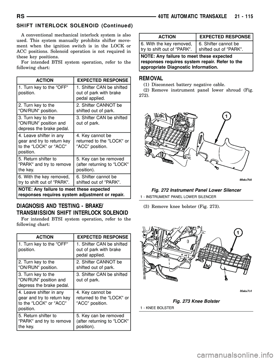
(1) Disconnect battery negative cable.
(2) Remove instrument panel lower shroud (Fig.
272).
(3) Remove knee bolster (Fig. 273).
Fig. 272 Instrument Panel Lower Silencer
1 - INSTRUMENT PANEL LOWER SILENCER
Fig. 273 Knee Bolster
1 - KNEE BOLSTER
RS40TE AUTOMATIC TRANSAXLE21 - 115
SHIFT INTERLOCK SOLENOID (Continued)