2005 CHRYSLER VOYAGER ail
[x] Cancel search: ailPage 1341 of 2339
SPECIAL TOOLS
EXHAUST SYSTEM
CATALYTIC CONVERTER
DESCRIPTION
The toe board three-way catalytic converter is con-
nected to the exhaust manifold by the use of flex
joint and a gasket. The outlet connects to the muffler
inlet pipe and is secured with a band type clamp
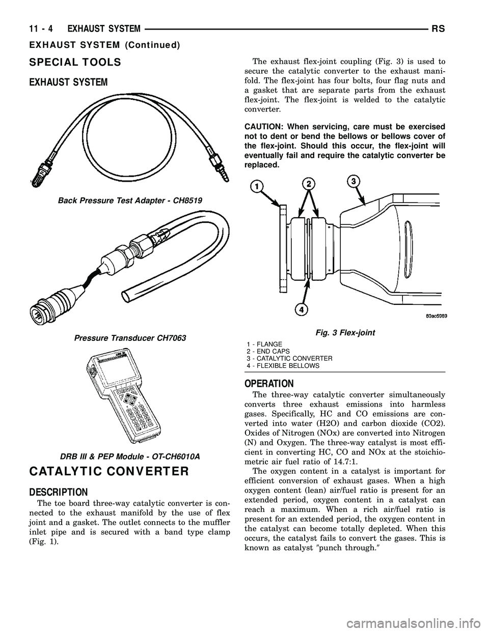
(Fig. 1).The exhaust flex-joint coupling (Fig. 3) is used to
secure the catalytic converter to the exhaust mani-
fold. The flex-joint has four bolts, four flag nuts and
a gasket that are separate parts from the exhaust
flex-joint. The flex-joint is welded to the catalytic
converter.
CAUTION: When servicing, care must be exercised
not to dent or bend the bellows or bellows cover of
the flex-joint. Should this occur, the flex-joint will
eventually fail and require the catalytic converter be
replaced.
OPERATION
The three-way catalytic converter simultaneously
converts three exhaust emissions into harmless
gases. Specifically, HC and CO emissions are con-
verted into water (H2O) and carbon dioxide (CO2).
Oxides of Nitrogen (NOx) are converted into Nitrogen
(N) and Oxygen. The three-way catalyst is most effi-
cient in converting HC, CO and NOx at the stoichio-
metric air fuel ratio of 14.7:1.
The oxygen content in a catalyst is important for
efficient conversion of exhaust gases. When a high
oxygen content (lean) air/fuel ratio is present for an
extended period, oxygen content in a catalyst can
reach a maximum. When a rich air/fuel ratio is
present for an extended period, the oxygen content in
the catalyst can become totally depleted. When this
occurs, the catalyst fails to convert the gases. This is
known as catalyst9punch through.9
Back Pressure Test Adapter - CH8519
Pressure Transducer CH7063
DRB III & PEP Module - OT-CH6010A
Fig. 3 Flex-joint
1 - FLANGE
2 - END CAPS
3 - CATALYTIC CONVERTER
4 - FLEXIBLE BELLOWS
11 - 4 EXHAUST SYSTEMRS
EXHAUST SYSTEM (Continued)
Page 1342 of 2339
Catalyst operation is dependent on its ability to
store and release the oxygen needed to complete the
emissions-reducing chemical reactions. As a catalyst
deteriorates, its ability to store oxygen is reduced.
Since the catalyst's ability to store oxygen is some-
what related to proper operation, oxygen storage can
be used as an indicator of catalyst performance.
Refer to the appropriate Diagnostic Information for
diagnosis of a catalyst related Diagnostic Trouble
Code (DTC).
The combustion reaction caused by the catalyst
releases additional heat in the exhaust system, caus-
ing temperature increases in the area of the reactor
under severe operating conditions. Such conditions
can exist when the engine misfires or otherwise does
not operate at peak efficiency.Do notremove spark
plug wires from plugs or by any other means short
out cylinders. Failure of the catalytic converter can
occur due to temperature increases caused by
unburned fuel passing through the converter. This
deterioration of the catalyst core can result in exces-
sively high emission levels, noise complaints, and
exhaust restrictions.
Unleaded gasoline must be used to avoid ruining
the catalyst core. Do not allow engine to operate
above 1200 RPM in neutral for extended periods over
5 minutes. This condition may result in excessive
exhaust system/floor pan temperatures because of no
air movement under the vehicle.
The flex joint allows flexing as the engine moves,
preventing breakage that could occur from the back-
and-forth motion of a transverse mounted engine.
CAUTION: Due to exterior physical similarities of
some catalytic converters with pipe assemblies,
extreme care should be taken with replacement
parts. There are internal converter differences
required in some parts of the country (particularly
vehicles built for States with strict emission
requirements) and between model years.
REMOVAL
(1) Loosen clamp and disconnect the muffler/reso-
nator assembly from catalytic converter pipe.
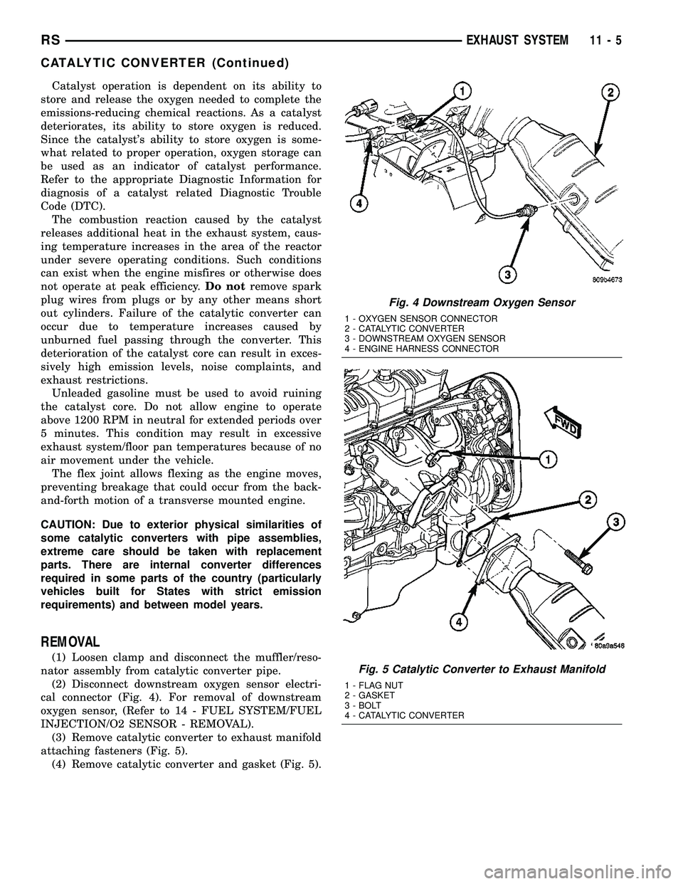
(2) Disconnect downstream oxygen sensor electri-
cal connector (Fig. 4). For removal of downstream
oxygen sensor, (Refer to 14 - FUEL SYSTEM/FUEL
INJECTION/O2 SENSOR - REMOVAL).
(3) Remove catalytic converter to exhaust manifold
attaching fasteners (Fig. 5).
(4) Remove catalytic converter and gasket (Fig. 5).
Fig. 4 Downstream Oxygen Sensor
1 - OXYGEN SENSOR CONNECTOR
2 - CATALYTIC CONVERTER
3 - DOWNSTREAM OXYGEN SENSOR
4 - ENGINE HARNESS CONNECTOR
Fig. 5 Catalytic Converter to Exhaust Manifold
1 - FLAG NUT
2 - GASKET
3 - BOLT
4 - CATALYTIC CONVERTER
RSEXHAUST SYSTEM11-5
CATALYTIC CONVERTER (Continued)
Page 1343 of 2339
INSPECTION
WARNING: THE NORMAL OPERATING TEMPERA-
TURE OF THE EXHAUST SYSTEM IS VERY HIGH.
THEREFORE, NEVER ATTEMPT TO SERVICE ANY
PART OF THE EXHAUST SYSTEM UNTIL IT IS
COOLED. SPECIAL CARE SHOULD BE TAKEN
WHEN WORKING NEAR THE CATALYTIC CON-
VERTER. THE TEMPERATURE OF THE CONVERTER
RISES TO A HIGH LEVEL AFTER A SHORT PERIOD
OF ENGINE OPERATION TIME.
Check catalytic converter for a flow restriction.
(Refer to 11 - EXHAUST SYSTEM - DIAGNOSIS
AND TESTING) Exhaust System Restriction Check
for procedure.
Visually inspect the catalytic converter element by
using a borescope or equivalent. Remove oxygen sen-
sor(s) and insert borescope. If borescope is not avail-
able, remove converter and inspect element using a
flashlight. Inspect element for cracked or melted sub-
strate.
NOTE: Before replacing a catalytic converter, deter-
mine the root cause of failure. Most catalytic con-
verter failures are caused by air, fuel or ignition
problems. (Refer to Appropriate Diagnostic Informa-
tion) for test procedures.
INSTALLATION
(1) Position new gasket onto the manifold flange
and install catalytic converter (Fig. 5). Tighten fas-
teners to 37 N´m (325 in. lbs.).
NOTE: Be careful not to twist or kink the oxygen
sensor wires.
(2) Install (if removed) and connect the down-
stream oxygen sensor (Fig. 4).
(3) Install the muffler/resonator assembly. (Refer
to 11 - EXHAUST SYSTEM/MUFFLER - INSTALLA-
TION)
(4) Start the engine and inspect for exhaust leaks.
Repair exhaust leaks as necessary.
(5) Check the exhaust system for contact with the
body panels. Make the necessary adjustments, if
needed.
CROSS-OVER PIPE - 3.3/3.8L
REMOVAL
(1) Disconnect negative cable from battery.
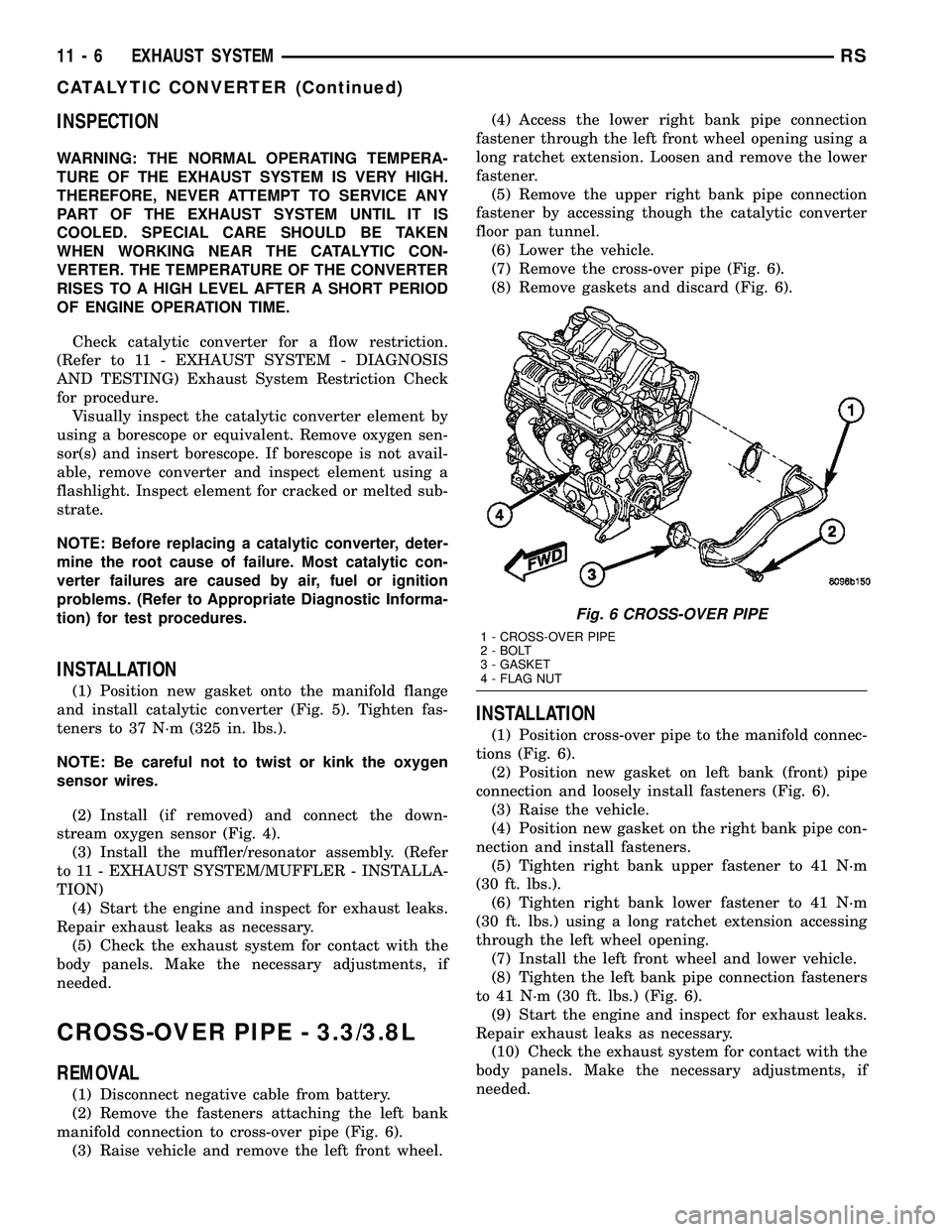
(2) Remove the fasteners attaching the left bank
manifold connection to cross-over pipe (Fig. 6).
(3) Raise vehicle and remove the left front wheel.(4) Access the lower right bank pipe connection
fastener through the left front wheel opening using a
long ratchet extension. Loosen and remove the lower
fastener.
(5) Remove the upper right bank pipe connection
fastener by accessing though the catalytic converter
floor pan tunnel.
(6) Lower the vehicle.
(7) Remove the cross-over pipe (Fig. 6).
(8) Remove gaskets and discard (Fig. 6).
INSTALLATION
(1) Position cross-over pipe to the manifold connec-
tions (Fig. 6).
(2) Position new gasket on left bank (front) pipe
connection and loosely install fasteners (Fig. 6).
(3) Raise the vehicle.
(4) Position new gasket on the right bank pipe con-
nection and install fasteners.
(5) Tighten right bank upper fastener to 41 N´m
(30 ft. lbs.).
(6) Tighten right bank lower fastener to 41 N´m
(30 ft. lbs.) using a long ratchet extension accessing
through the left wheel opening.
(7) Install the left front wheel and lower vehicle.
(8) Tighten the left bank pipe connection fasteners
to 41 N´m (30 ft. lbs.) (Fig. 6).
(9) Start the engine and inspect for exhaust leaks.
Repair exhaust leaks as necessary.
(10) Check the exhaust system for contact with the
body panels. Make the necessary adjustments, if
needed.
Fig. 6 CROSS-OVER PIPE
1 - CROSS-OVER PIPE
2 - BOLT
3 - GASKET
4 - FLAG NUT
11 - 6 EXHAUST SYSTEMRS
CATALYTIC CONVERTER (Continued)
Page 1345 of 2339
CAUTION: When servicing the exhaust system, care
must be exercised not to dent or bend the bellows
of the flex-joint. Should this occur, the flex-joint will
eventually fail, requiring replacement of the cata-
lytic converter.
(3) Disconnect the right side axle half shaft from
the rear differential module (AWD equipped only).
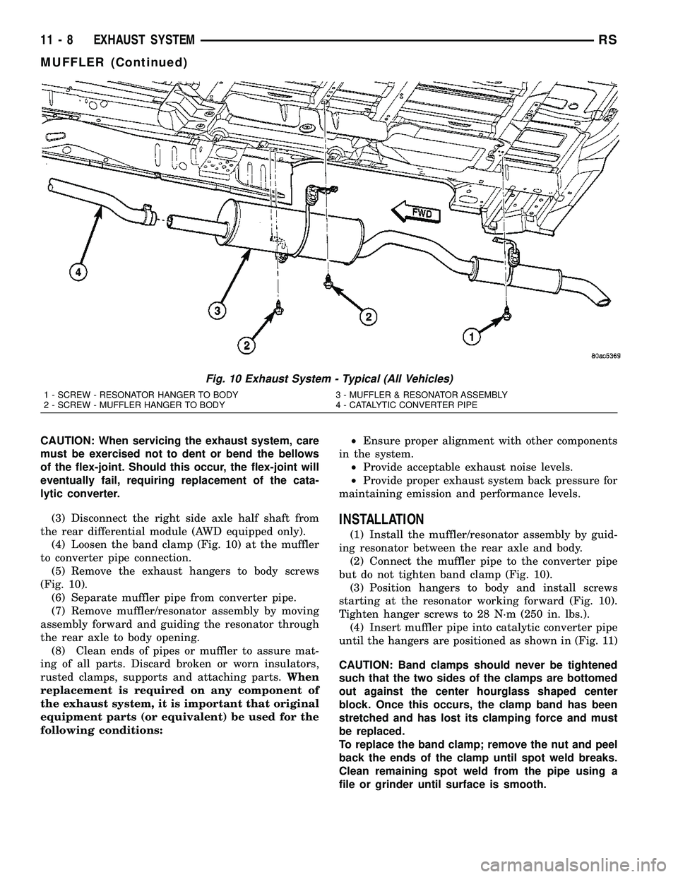
(4) Loosen the band clamp (Fig. 10) at the muffler
to converter pipe connection.
(5) Remove the exhaust hangers to body screws
(Fig. 10).
(6) Separate muffler pipe from converter pipe.
(7) Remove muffler/resonator assembly by moving
assembly forward and guiding the resonator through
the rear axle to body opening.
(8) Clean ends of pipes or muffler to assure mat-
ing of all parts. Discard broken or worn insulators,
rusted clamps, supports and attaching parts.When
replacement is required on any component of
the exhaust system, it is important that original
equipment parts (or equivalent) be used for the
following conditions:²Ensure proper alignment with other components
in the system.
²Provide acceptable exhaust noise levels.
²Provide proper exhaust system back pressure for
maintaining emission and performance levels.
INSTALLATION
(1) Install the muffler/resonator assembly by guid-
ing resonator between the rear axle and body.
(2) Connect the muffler pipe to the converter pipe
but do not tighten band clamp (Fig. 10).
(3) Position hangers to body and install screws
starting at the resonator working forward (Fig. 10).
Tighten hanger screws to 28 N´m (250 in. lbs.).
(4) Insert muffler pipe into catalytic converter pipe
until the hangers are positioned as shown in (Fig. 11)
CAUTION: Band clamps should never be tightened
such that the two sides of the clamps are bottomed
out against the center hourglass shaped center
block. Once this occurs, the clamp band has been
stretched and has lost its clamping force and must
be replaced.
To replace the band clamp; remove the nut and peel
back the ends of the clamp until spot weld breaks.
Clean remaining spot weld from the pipe using a
file or grinder until surface is smooth.
Fig. 10 Exhaust System - Typical (All Vehicles)
1 - SCREW - RESONATOR HANGER TO BODY 3 - MUFFLER & RESONATOR ASSEMBLY
2 - SCREW - MUFFLER HANGER TO BODY 4 - CATALYTIC CONVERTER PIPE
11 - 8 EXHAUST SYSTEMRS
MUFFLER (Continued)
Page 1350 of 2339
FRONT BUMPER
REINFORCEMENT
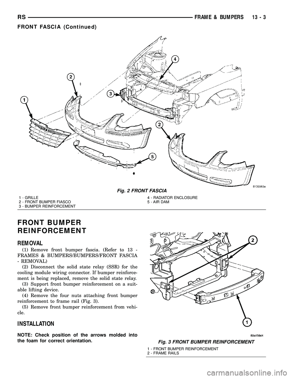
REMOVAL
(1) Remove front bumper fascia. (Refer to 13 -
FRAMES & BUMPERS/BUMPERS/FRONT FASCIA
- REMOVAL)
(2) Disconnect the solid state relay (SSR) for the
cooling module wiring connector. If bumper reinforce-
ment is being replaced, remove the solid state relay.
(3) Support front bumper reinforcement on a suit-
able lifting device.
(4) Remove the four nuts attaching front bumper
reinforcement to frame rail (Fig. 3).
(5) Remove front bumper reinforcement from vehi-
cle.
INSTALLATION
NOTE: Check position of the arrows molded into
the foam for correct orientation.
Fig. 2 FRONT FASCIA
1 - GRILLE
2 - FRONT BUMPER FIASCO
3 - BUMPER REINFORCEMENT4 - RADIATOR ENCLOSURE
5 - AIR DAM
Fig. 3 FRONT BUMPER REINFORCEMENT
1 - FRONT BUMPER REINFORCEMENT
2 - FRAME RAILS
RSFRAME & BUMPERS13-3
FRONT FASCIA (Continued)
Page 1351 of 2339
(1) Support front bumper reinforcement using a
suitable lifting device and lift into position.
(2) Install the four nuts attaching reinforcement to
frame rails. Tighten nuts to 54 N´m (40 ft. lbs.)
torque.
(3) Connect the solid state relay (SSR) wiring con-
nector. If bumper reinforcement was replaced, install
the solid state relay onto the bumper reinforcement.
(4) Install front fascia. (Refer to 13 - FRAMES &
BUMPERS/BUMPERS/FRONT FASCIA - INSTAL-
LATION).
REAR FASCIA
REMOVAL
(1) Open liftgate.
(2) Remove attaching screw from upper fascia to
the liftgate tower, right side and left side.
(3) Hoist and support vehicle with safety stands.
(4) Disconnect rear park assist wire connector, if
equipped.
(5) Remove the three screws attaching rear fascia
to rear fascia brackets on right side and left side
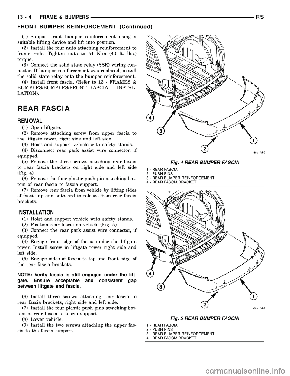
(Fig. 4).
(6) Remove the four plastic push pin attaching bot-
tom of rear fascia to fascia support.
(7) Remove rear fascia from vehicle by lifting sides
of fascia up and outboard to release from rear fascia
brackets.
INSTALLATION
(1) Hoist and support vehicle with safety stands.
(2) Position rear fascia on vehicle (Fig. 5).
(3) Connect the rear park assist wire connector, if
equipped.
(4) Engage front edge of fascia under the liftgate
tower. Install screw in liftgate tower right side and
left side.
(5) Engage sides of fascia to top and front edge of
the rear fascia brackets.
NOTE: Verify fascia is still engaged under the lift-
gate. Ensure acceptable and consistent gap
between liftgate and fascia.
(6) Install three screws attaching rear fascia to
rear fascia brackets, right side and left side.
(7) Install the four plastic push pins attaching bot-
tom of rear fascia to fascia support.
(8) Lower vehicle.
(9) Install the two screws attaching the upper fas-
cia to the fascia support.
Fig. 4 REAR BUMPER FASCIA
1 - REAR FASCIA
2 - PUSH PINS
3 - REAR BUMPER REINFORCEMENT
4 - REAR FASCIA BRACKET
Fig. 5 REAR BUMPER FASCIA
1 - REAR FASCIA
2 - PUSH PINS
3 - REAR BUMPER REINFORCEMENT
4 - REAR FASCIA BRACKET
13 - 4 FRAME & BUMPERSRS
FRONT BUMPER REINFORCEMENT (Continued)
Page 1352 of 2339
REAR BUMPER
REINFORCEMENT
REMOVAL
(1) Remove rear bumper fascia. (Refer to 13 -
FRAMES & BUMPERS/BUMPERS/REAR FASCIA -
REMOVAL)
(2) Support rear bumper reinforcement on a suit-
able lifting device.
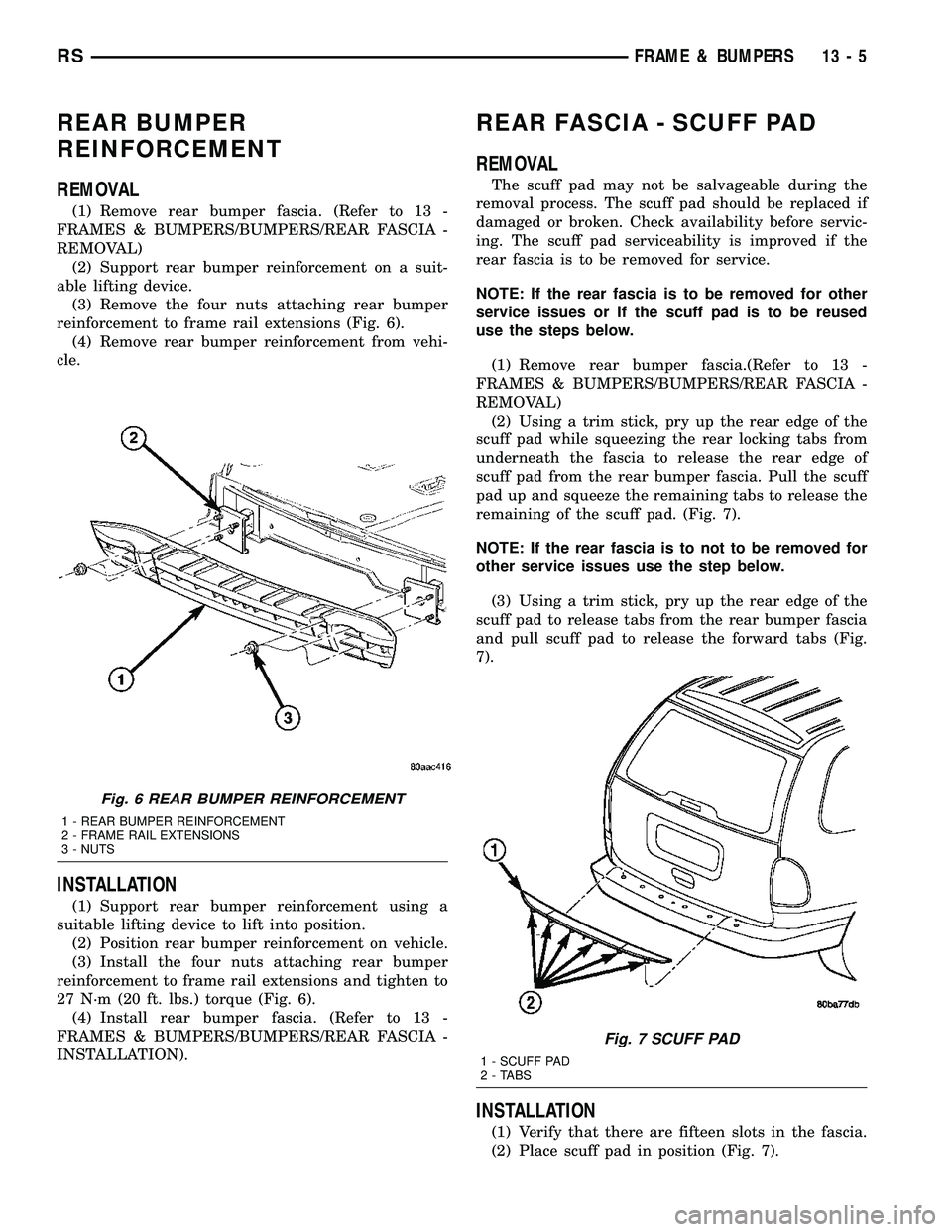
(3) Remove the four nuts attaching rear bumper
reinforcement to frame rail extensions (Fig. 6).
(4) Remove rear bumper reinforcement from vehi-
cle.
INSTALLATION
(1) Support rear bumper reinforcement using a
suitable lifting device to lift into position.
(2) Position rear bumper reinforcement on vehicle.
(3) Install the four nuts attaching rear bumper
reinforcement to frame rail extensions and tighten to
27 N´m (20 ft. lbs.) torque (Fig. 6).
(4) Install rear bumper fascia. (Refer to 13 -
FRAMES & BUMPERS/BUMPERS/REAR FASCIA -
INSTALLATION).
REAR FASCIA - SCUFF PAD
REMOVAL
The scuff pad may not be salvageable during the
removal process. The scuff pad should be replaced if
damaged or broken. Check availability before servic-
ing. The scuff pad serviceability is improved if the
rear fascia is to be removed for service.
NOTE: If the rear fascia is to be removed for other
service issues or If the scuff pad is to be reused
use the steps below.
(1) Remove rear bumper fascia.(Refer to 13 -
FRAMES & BUMPERS/BUMPERS/REAR FASCIA -
REMOVAL)
(2) Using a trim stick, pry up the rear edge of the
scuff pad while squeezing the rear locking tabs from
underneath the fascia to release the rear edge of
scuff pad from the rear bumper fascia. Pull the scuff
pad up and squeeze the remaining tabs to release the
remaining of the scuff pad. (Fig. 7).
NOTE: If the rear fascia is to not to be removed for
other service issues use the step below.
(3) Using a trim stick, pry up the rear edge of the
scuff pad to release tabs from the rear bumper fascia
and pull scuff pad to release the forward tabs (Fig.
7).
INSTALLATION
(1) Verify that there are fifteen slots in the fascia.
(2) Place scuff pad in position (Fig. 7).
Fig. 6 REAR BUMPER REINFORCEMENT
1 - REAR BUMPER REINFORCEMENT
2 - FRAME RAIL EXTENSIONS
3 - NUTS
Fig. 7 SCUFF PAD
1 - SCUFF PAD
2 - TABS
RSFRAME & BUMPERS13-5
Page 1353 of 2339
(3) Align and insert the center forward tab.
(4) Align the remaining tabs and press into the
slots, starting in the center and working outboard.
(5) Assure all tabs are fully engaged into the fas-
cia.
(6) If rear bumper fascia has been removed install.
(Refer to 13 - FRAME & BUMPERS/BUMPERS/
REAR FASCIA - INSTALLATION).
FRAME
SPECIFICATIONS
SPECIFICATIONS - FRAME DIMENSIONS
Frame dimensions are listed in metric scale. All
dimensions are from center to center of PrincipalLocating Point (PLP), or from center to center of PLP
and fastener location.
VEHICLE PREPARATION
Position the vehicle on a frame alignment rack,
refer to instructions provided with equipment being
used. Adjust the vehicle PLP heights to the specified
dimension above the work surface (datum line). Ver-
tical dimensions can be taken from the datum line to
the locations indicated were applicable.
INDEX
DESCRIPTION FIGURE
CROSSMEMBER DIMENSIONS 8
ENGINE BOX - TOP VIEW 9
ENGINE COMPARTMENT AND FRAME RAIL - SIDE VIEW 10
FULL VEHICLE - BOTTOM VIEW 11
13 - 6 FRAME & BUMPERSRS
REAR FASCIA - SCUFF PAD (Continued)