2005 CHRYSLER VOYAGER roof rack
[x] Cancel search: roof rackPage 269 of 2339

ANTENNA MODULE - EXPORT
DESCRIPTION
The antenna module is an electromagnetic circuit
component designed to capture and enhance RF
(Radio Frequency) signals in both the AM and FM
broadcast bands. The antenna module is mounted to
the right rear roof rail under the headliner. The mod-
ule is grounded through the mounting bracket and
fastener. The module has a two wire electrical con-
nector that connects to the integral radio antenna,located on the right rear quarter glass. There is also
an electrical connector for battery voltage and a coax
cable connector.OPERATION
The antenna module receives both AM and FM
radio signals supplied by the side window integral
radio antenna system and selectively amplifies them.
The amplified signal is then sent through the body
length coax cable to the radio input.
DIAGNOSIS AND TESTING
ANTENNA MODULE - EXPORT
CONDITION POSSIBLE CAUSES CORRECTION
NO AM RECEPTION,
WEAK FM RECEPTION1. Antenna module to antenna
connector open or disconnected.1. Repair open, reconnect
antenna module connector to
glass mounted antenna.
2. Coax open or disconnected. 2. Repair open, reconnect coax.
3. No battery power at antenna
module.3. Check fuse. if okay, repair
open in battery voltage circuit.
NO AM OR FM
RECEPTION1. Coax disconnected at radio. 1. Reconnect coax.
2. Coax shorted to ground. 2. Repair or Replace coax
WEAK OR NO AM/FM
RECEPTION1. Antenna Module faulty. 1. Replace antenna module
REMOVAL
(1) Disconnect and isolate the battery negative
cable.
(2) Lower headliner as necessary to access
antenna module (Fig. 6).
(3) Disconnect antenna coax cable lead and electri-
cal harness connector from antenna module.
(4) Disconnect the antenna module connector from
the quarter glass.
(5) Remove the mounting screw and the antenna
module.
INSTALLATION
(1) Install the antenna module and the mounting
fastener.
(2) Connect the antenna connector to the quarter
glass.
(3) Connect the antenna lead and electrical con-
nector to the antenna module.
(4) Raise and install headliner.
(5) Connect the battery negative cable.
Fig. 6 ANTENNA MODULE
1 - ANTENNA MODULE
2 - ANTENNA MODULE CONNECTOR
8A - 10 AUDIO/VIDEORS
Page 500 of 2339

The hybrid-type inflator for each airbag is secured
to the roof rail just behind the C-pillar. The inflator
bracket and the airbag cushion are secured with both
plastic push-in fasteners and screws to the roof rail.
A short pigtail wire harness connects the curtain air-
bag inflator to the body wire harness.
The curtain airbag cannot be adjusted or repaired
and must be replaced if deployed, faulty, or in any
way damaged. Once a curtain airbag has been
deployed, the complete airbag unit (Refer to 8 -
ELECTRICAL/RESTRAINTS - STANDARD PROCE-
DURE - SERVICE AFTER AN AIRBAG DEPLOY-
MENT), headliner, upper A/B/C and D-pillar trim,
and all other visibly damaged components must be
replaced (Refer to Section 23 - BODY/INTERIOR for
complete body interior Removal and Installation pro-
cedures). Refer to the appropriate diagnostic informa-
tion for complete diagnosis and testing or the curtain
airbags.The curtain airbags also contain Head Impact
Counter Measures (Fig. 14). These injection molded
plastic components help to reduce the likelihood of
injury or death in the event of a side impact event.
They are attached to the curtain airbag and are also
used to mount the curtain to the inside roof rail.
Their purpose is to maintain a flat surface in which
the deployed airbag to be pressed against when inte-
rior occupants/forces are pushing outwards.
OPERATION
Each curtain airbag is deployed individually by an
electrical signal generated by the Occupant Restraint
Controller (ORC) to which it is connected through
left or right curtain airbag line 1 and line 2 (or
squib) circuits. The hybrid-type inflator assembly for
each airbag contains a small canister of highly com-
pressed inert gas. When the ORC sends the proper
electrical signal to the airbag inflator, the electrical
energy creates enough heat to ignite chemical pellets
within the inflator. Once ignited, these chemicals
burn rapidly and produce the pressure necessary to
rupture a containment disk in the inert gas canister.
The inflator and inert gas canister are sealed and
connected to a tubular manifold so that all of the
released gas is directed into the folded curtain airbag
cushion, causing the cushion to inflate.
Fig. 11 CURTAIN AIRBAG
Fig. 12 SRS LOGO
RSRESTRAINTS8O-13
CURTAIN AIRBAG (Continued)
Page 502 of 2339

(3) Remove the headliner from the vehicle (Refer
to 23 - BODY/INTERIOR/HEADLINER -
REMOVAL).
(4) Disconnect the curtain airbag squib connector
(Fig. 15).
(5) Remove the bolt from the curtain airbag front
tether and unclip from the A-pillar (Fig. 16).(6) Remove the screws that secure the curtain air-
bag to the spring nuts in the roof side rail (Fig. 17).
(7) Remove the bolt from the curtain airbag infla-
tor mounting bracket (Fig. 18).
(8) Remove the bolts retaining the curtain airbag
to the roof rail in the d-pillar area (Fig. 19).
(9) Grasp the curtain airbag, using a trim stick
(special tool #C-4755) or equivalent, gently pry out on
push fasteners to disengage the curtain airbag and
remove it from its mounting location in the side roof
rail (Fig. 17).
(10) Remove the curtain airbag from the vehicle as
a unit.
Fig. 15 CURTAIN AIRBAG SQUIB CONNECTION
1 - CURTAIN AIRBAG INFLATOR
2 - CURTAIN AIRBAG SQUIB CONNECTOR
3 - C-PILLAR
Fig. 16 CURTAIN AIRBAG FRONT TETHER
ATTACHMENT
1 - A-PILLAR
2 - CURTAIN AIRBAG PUSH FASTENER
3 - CURTAIN AIRBAG FRONT TETHER
4 - CURTAIN AIRBAG FRONT TETHER ATTACHMENT HOOK/
BOLT
Fig. 17 CURTAIN AIRBAG REMOVE/INSTALL
1 - CURTAIN AIRBAG ATTACHMENT LOCATIONS
2 - SLIDING DOOR OPENING/ROOF RAIL
3 - CURTAIN AIRBAG
Fig. 18 CURTAIN AIRBAG INFLATOR MOUNTING
BRACKET ATTACHMENT
1 - CURTAIN AIRBAG INFLATOR MOUNTING BRACKET
2 - CURTAIN AIRBAG SQUIB CONNECTOR
3 - C-PILLAR
RSRESTRAINTS8O-15
CURTAIN AIRBAG (Continued)
Page 503 of 2339

INSTALLATION
(1) Position curtain airbag over retaining holes in
roof rail and firmly snap into place (Fig. 17).
(2) Install the curtain airbag retaining bolts (Fig.
17).
(3) Engage the side curtain airbag front tether in
the A-pillar and install retaining bolt (Fig. 16).
(4) Install the bolt in the curtain airbag inflator
mounting bracket (Fig. 18).
(5) Install the retaining bolts at the d-pillar (Fig.
19).
(6) Connect the curtain airbag squib connector
(Fig. 15).
(7) Install the headliner into the vehicle (Refer to
23 - BODY/INTERIOR/HEADLINER - INSTALLA-
TION).
WARNING: Do not connect the battery negative
cable (Refer to 8 - ELECTRICAL/RESTRAINTS -
DIAGNOSIS AND TESTING - AIRBAG SYSTEM). Per-
sonal injury or death may result if the system test
is not performed first.
(8) Verify vehicle and system operation.
(9) Close hood.
DRIVER AIRBAG
DESCRIPTION
The injection molded, thermoplastic driver airbag
protective trim cover is the most visible part of the
driver airbag. The driver airbag is located in the cen-
ter of the steering wheel, where it is secured to the
steering wheel armature. Concealed beneath the
driver airbag trim cover are the horn switch, thefolded airbag cushion, the airbag cushion retainer,
the airbag housing, the airbag inflator, and the
retainers that secure the inflator to the airbag hous-
ing. The airbag cushion, housing, and inflator are
secured within an integral receptacle molded into the
back of the trim cover.
The resistive membrane-type horn switch is
secured with heat stakes to the inside surface of the
driver airbag trim cover, between the trim cover and
the folded airbag cushion. The horn switch ground
pigtail wire has a female spade terminal connector
that receives a path to ground through a male spade
terminal that is integral to the driver airbag housing
stamping and is located near the upper right corner
on the back of the housing. The horn switch feed pig-
tail wire has a white, molded plastic insulator that is
secured by an integral retainer to a mounting hole
located near the lower left corner on the back of the
housing, and is connected to the vehicle electrical
system through a take out and connector of the steer-
ing wheel wire harness.
The airbag is a multistage unit that deploys with
less force than those previously used. The airbag
inflator is a dual-initiator, non-azide, pyrotechnic-
type unit with four mounting studs and is secured to
the stamped metal airbag housing using four hex
nuts with washers. Two keyed and color-coded con-
nector receptacles on the driver airbag inflator con-
nect the two inflator initiators to the vehicle
electrical system through two yellow or black-jack-
eted, two-wire pigtail harnesses of the clockspring.
The driver airbag, trim cover, and horn switch unit
cannot be repaired, and must be replaced if deployed
or in any way damaged.
OPERATION
The Driver Airbag Trim Cover contains the horn
switch, inflator device, and a fabric bag. The driver
airbag trim cover/horn switch is not serviced sepa-
rately from the driver airbag components.
When the front airbag system is deployed, the fol-
lowingMUSTbe replaced:
²Complete Steering Column Assembly
²Lower Steering Column Coupler
²Steering Wheel.
²Clockspring.
²Driver Airbag
²Passenger Airbag
²Knee Blocker Airbag
²Upper Instrument Panel with Pad
²Front Seat Belt Buckles, both driver and passen-
ger with integral tensioners.
Fig. 19 CURTAIN AIRBAG D-PILLAR ATTACHMENT
1 - CURTAIN AIRBAG D-PILLAR ATTACHMENT LOCATIONS
2 - D-PILLAR
3 - ROOF RAIL AT REAR QUARTER GLASS
8O - 16 RESTRAINTSRS
CURTAIN AIRBAG (Continued)
Page 1018 of 2339

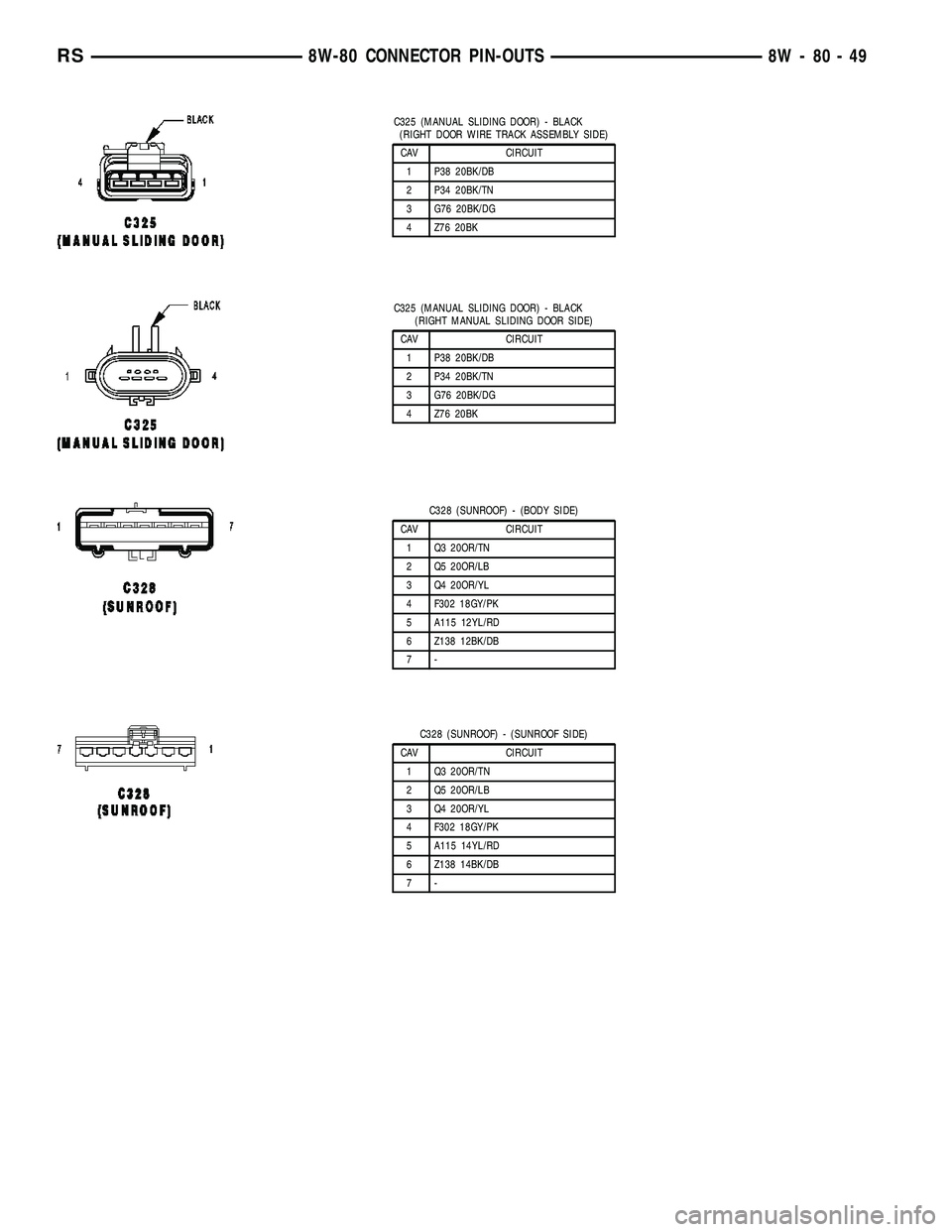
C325 (MANUAL SLIDING DOOR) - BLACK
(RIGHT DOOR WIRE TRACK ASSEMBLY SIDE)
CAV CIRCUIT
1 P38 20BK/DB
2 P34 20BK/TN
3 G76 20BK/DG
4 Z76 20BK
C325 (MANUAL SLIDING DOOR) - BLACK
(RIGHT MANUAL SLIDING DOOR SIDE)
CAV CIRCUIT
1 P38 20BK/DB
2 P34 20BK/TN
3 G76 20BK/DG
4 Z76 20BK
C328 (SUNROOF) - (BODY SIDE)
CAV CIRCUIT
1 Q3 20OR/TN
2 Q5 20OR/LB
3 Q4 20OR/YL
4 F302 18GY/PK
5 A115 12YL/RD
6 Z138 12BK/DB
7-
C328 (SUNROOF) - (SUNROOF SIDE)
CAV CIRCUIT
1 Q3 20OR/TN
2 Q5 20OR/LB
3 Q4 20OR/YL
4 F302 18GY/PK
5 A115 14YL/RD
6 Z138 14BK/DB
7-
RS8W-80 CONNECTOR PIN-OUTS8W-80-49
Page 1790 of 2339

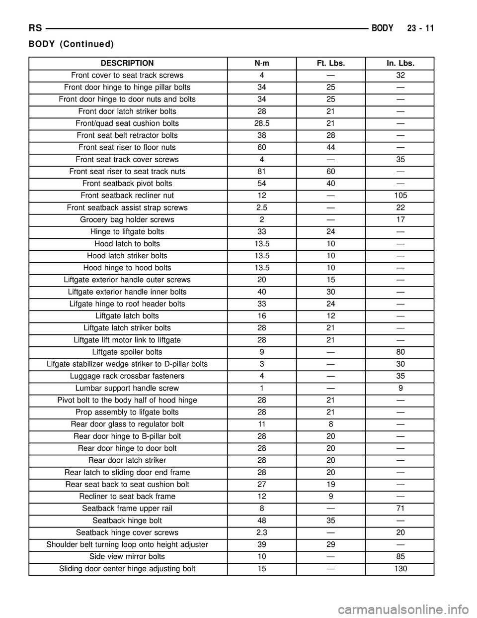
DESCRIPTION N´m Ft. Lbs. In. Lbs.
Front cover to seat track screws 4 Ð 32
Front door hinge to hinge pillar bolts 34 25 Ð
Front door hinge to door nuts and bolts 34 25 Ð
Front door latch striker bolts 28 21 Ð
Front/quad seat cushion bolts 28.5 21 Ð
Front seat belt retractor bolts 38 28 Ð
Front seat riser to floor nuts 60 44 Ð
Front seat track cover screws 4 Ð 35
Front seat riser to seat track nuts 81 60 Ð
Front seatback pivot bolts 54 40 Ð
Front seatback recliner nut 12 Ð 105
Front seatback assist strap screws 2.5 Ð 22
Grocery bag holder screws 2 Ð 17
Hinge to liftgate bolts 33 24 Ð
Hood latch to bolts 13.5 10 Ð
Hood latch striker bolts 13.5 10 Ð
Hood hinge to hood bolts 13.5 10 Ð
Liftgate exterior handle outer screws 20 15 Ð
Liftgate exterior handle inner bolts 40 30 Ð
Lifgate hinge to roof header bolts 33 24 Ð
Liftgate latch bolts 16 12 Ð
Liftgate latch striker bolts 28 21 Ð
Liftgate lift motor link to liftgate 28 21 Ð
Liftgate spoiler bolts 9 Ð 80
Lifgate stabilizer wedge striker to D-pillar bolts 3 Ð 30
Luggage rack crossbar fasteners 4 Ð 35
Lumbar support handle screw 1 Ð 9
Pivot bolt to the body half of hood hinge 28 21 Ð
Prop assembly to lifgate bolts 28 21 Ð
Rear door glass to regulator bolt 11 8 Ð
Rear door hinge to B-pillar bolt 28 20 Ð
Rear door hinge to door bolt 28 20 Ð
Rear door latch striker 28 20 Ð
Rear latch to sliding door end frame 28 20 Ð
Rear seat back to seat cushion bolt 27 19 Ð
Recliner to seat back frame 12 9 Ð
Seatback frame upper rail 8 Ð 71
Seatback hinge bolt 48 35 Ð
Seatback hinge cover screws 2.3 Ð 20
Shoulder belt turning loop onto height adjuster 39 29 Ð
Side view mirror bolts 10 Ð 85
Sliding door center hinge adjusting bolt 15 Ð 130
RSBODY23-11
BODY (Continued)
Page 1791 of 2339

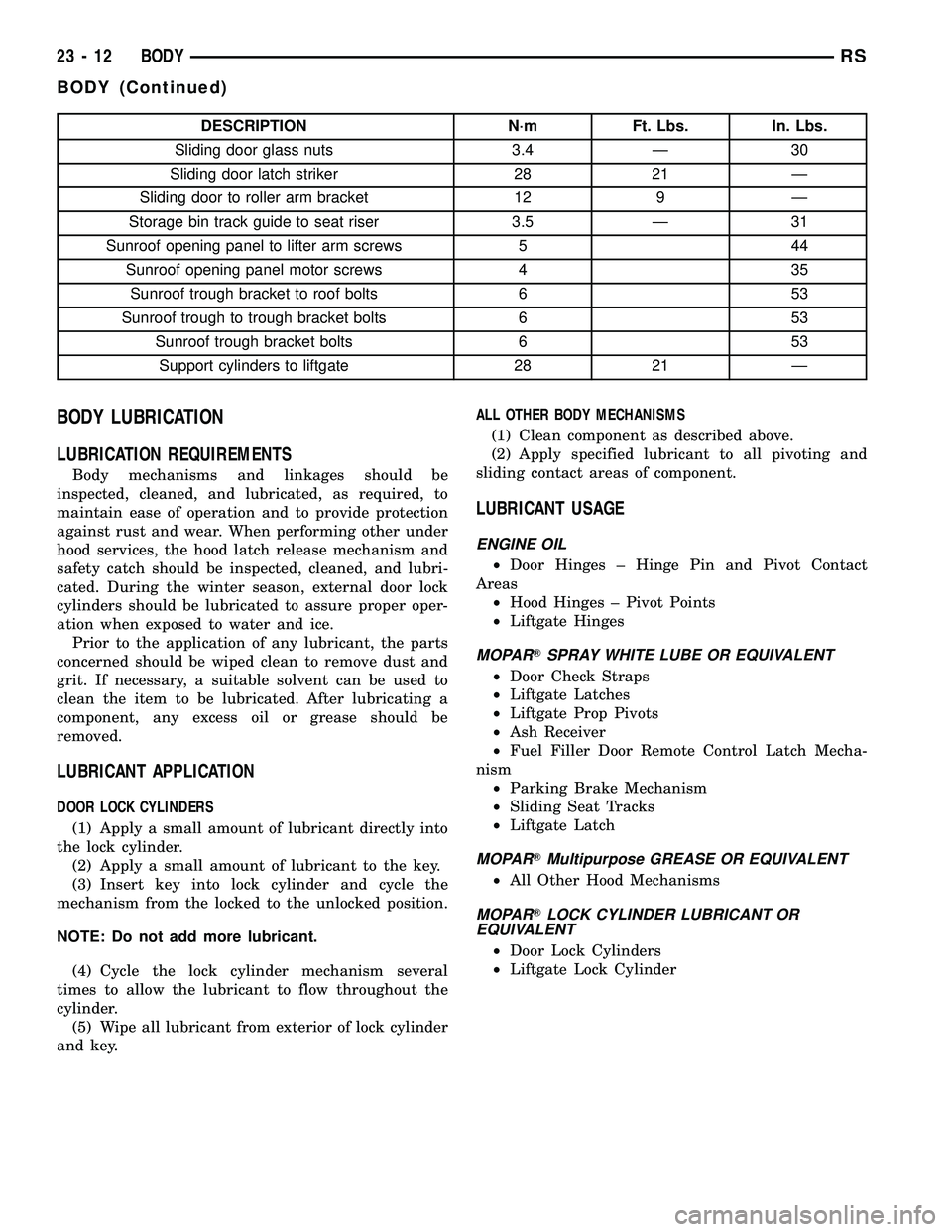
DESCRIPTION N´m Ft. Lbs. In. Lbs.
Sliding door glass nuts 3.4 Ð 30
Sliding door latch striker 28 21 Ð
Sliding door to roller arm bracket 12 9 Ð
Storage bin track guide to seat riser 3.5 Ð 31
Sunroof opening panel to lifter arm screws 5 44
Sunroof opening panel motor screws 4 35
Sunroof trough bracket to roof bolts 6 53
Sunroof trough to trough bracket bolts 6 53
Sunroof trough bracket bolts 6 53
Support cylinders to liftgate 28 21 Ð
BODY LUBRICATION
LUBRICATION REQUIREMENTS
Body mechanisms and linkages should be
inspected, cleaned, and lubricated, as required, to
maintain ease of operation and to provide protection
against rust and wear. When performing other under
hood services, the hood latch release mechanism and
safety catch should be inspected, cleaned, and lubri-
cated. During the winter season, external door lock
cylinders should be lubricated to assure proper oper-
ation when exposed to water and ice.
Prior to the application of any lubricant, the parts
concerned should be wiped clean to remove dust and
grit. If necessary, a suitable solvent can be used to
clean the item to be lubricated. After lubricating a
component, any excess oil or grease should be
removed.
LUBRICANT APPLICATION
DOOR LOCK CYLINDERS
(1) Apply a small amount of lubricant directly into
the lock cylinder.
(2) Apply a small amount of lubricant to the key.
(3) Insert key into lock cylinder and cycle the
mechanism from the locked to the unlocked position.
NOTE: Do not add more lubricant.
(4) Cycle the lock cylinder mechanism several
times to allow the lubricant to flow throughout the
cylinder.
(5) Wipe all lubricant from exterior of lock cylinder
and key.ALL OTHER BODY MECHANISMS
(1) Clean component as described above.
(2) Apply specified lubricant to all pivoting and
sliding contact areas of component.
LUBRICANT USAGE
ENGINE OIL
²Door Hinges ± Hinge Pin and Pivot Contact
Areas
²Hood Hinges ± Pivot Points
²Liftgate Hinges
MOPARTSPRAY WHITE LUBE OR EQUIVALENT
²Door Check Straps
²Liftgate Latches
²Liftgate Prop Pivots
²Ash Receiver
²Fuel Filler Door Remote Control Latch Mecha-
nism
²Parking Brake Mechanism
²Sliding Seat Tracks
²Liftgate Latch
MOPARTMultipurpose GREASE OR EQUIVALENT
²All Other Hood Mechanisms
MOPARTLOCK CYLINDER LUBRICANT OR
EQUIVALENT
²Door Lock Cylinders
²Liftgate Lock Cylinder
23 - 12 BODYRS
BODY (Continued)
Page 1810 of 2339

(4) Check door for height using character lines as
a reference. Also check roof contour as a controlling
factor.
Using the procedures noted below, adjust the side
door in the order the individual steps are called out.
DOOR FLUSHNESS ADJUSTMENT
(1) Check sliding door flushness at the C-pillar
striker.
(2) If the sliding door is under or over flush,
remove striker assembly and move thread plate over
keeping one bolt in plate so it will not fall between
inner and outer panels.
(3) Adjust the C-pillar striker in or out until the
door is flush. Then, the on size hole can be elongated
in the direction required. This can be done by grind-
ing or filing the sheet metal and then painting raw
edge to prevent rusting.
(4) Check upper B-pillar flushness to A-pillar
cover.
(5) The sliding door upper hinge can only be
moved outboard by addinga1mmshim behind the
hinge mounting area once the two attachment bolts
are removed and reinstalled.
(6) Check flushness at upper C-pillar.
(7) If upper C-pillar flushness is out of specifica-
tion use a heavy rubber mallet on the door assembly
until door is in specifications.
DOOR GAP ADJUSTMENT - UP/DOWN
(1) Check height of sliding door at the B-pillar and
C-pillar to determine which area is contributing the
greatest to the incorrect gaps.
(2) Visually inspect the sliding door for fitting low
at the top of the door by checking the alignment of
the top contour of the door to the quarter panel.
(3) If the sliding door is high at the C-pillar.
(a) Open the door to mid-point of travel.
(b) Mark outline of center hinge on sliding door
to assist in making adjustments.
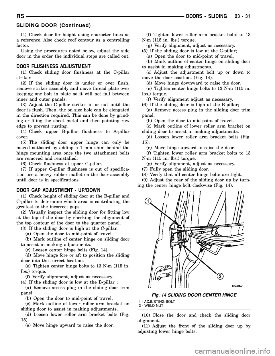
(c) Loosen center hinge bolts (Fig. 14).
(d) Move hinge fore or aft to position the sliding
door into the correct location.
(e) Tighten center hinge bolts to 13 N´m (115 in.
lbs.) torque.
(f) Verify alignment, adjust as necessary.
(4) If the sliding door is low at the B-pillar ;
(a) Remove access plug in the sliding door trim
panel.
(b) Open the door to mid-point of travel.
(c) Mark outline of lower roller arm bracket on
sliding door to assist in making adjustments.
(d) Loosen lower roller arm bracket bolts (Fig.
15).
(e) Move hinge upward to raise the door.(f) Tighten lower roller arm bracket bolts to 13
N´m (115 in. lbs.) torque.
(g) Verify alignment, adjust as necessary.
(5) If the sliding door is low at the C-pillar;
(a) Open the door to mid-point of travel.
(b) Mark outline of center hinge on sliding door
to assist in making adjustments.
(c) Adjust the adjustment bolt up or down to
move the door position. (Fig. 14).
(d) Move hinge downward to raise the door.
(e) Tighten center hinge bolts to 13 N´m (115 in.
lbs.) torque.
(f) Verify alignment adjust as necessary.
(6) If the sliding door is high at the B-pillar;
(a) Remove access plug in the sliding door trim
panel.
(b) Open the door to mid-point of travel.
(c) Mark outline of lower roller arm bracket on
sliding door to assist in making adjustments.
(d) Loosen lower roller arm bracket bolts (Fig.
15).
(e) Move hinge upward to raise the door.
(f) Tighten lower roller arm bracket bolts to 13
N´m (115 in. lbs.) torque.
(g) Verify alignment, adjust as necessary.
(7) Fully open the sliding door.
(8) Verify that all center hinge bolts are tight.
(9) Adjust the rear of the sliding door up by turn-
ing the center hinge bolt clockwise (Fig. 14).
(10) Close the door and check the sliding door
alignment.
(11) Adjust the front of the sliding door up by
adjusting lower hinge bolts.
Fig. 14 SLIDING DOOR CENTER HINGE
1 - ADJUSTING BOLT
2 - WELD NUT
RSDOORS - SLIDING23-31
SLIDING DOOR (Continued)