2005 CHRYSLER CARAVAN lock
[x] Cancel search: lockPage 2163 of 2339
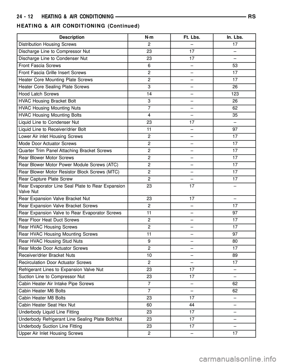
Description N´m Ft. Lbs. In. Lbs.
Distribution Housing Screws 2 ± 17
Discharge Line to Compressor Nut 23 17 ±
Discharge Line to Condenser Nut 23 17 ±
Front Fascia Screws 6 ± 53
Front Fascia Grille Insert Screws 2 ± 17
Heater Core Mounting Plate Screws 2 ± 17
Heater Core Sealing Plate Screws 3 ± 26
Hood Latch Screws 14 ± 123
HVAC Housing Bracket Bolt 3 ± 26
HVAC Housing Mounting Nuts 7 ± 62
HVAC Housing Mounting Bolts 4 ± 35
Liquid Line to Condenser Nut 23 17 ±
Liquid Line to Receiver/drier Bolt 11 ± 97
Lower Air inlet Housing Screws 2 ± 17
Mode Door Actuator Screws 2 ± 17
Quarter Trim Panel Attaching Bracket Screws 2 ± 17
Rear Blower Motor Screws 2 ± 17
Rear Blower Motor Power Module Screws (ATC) 2 ± 17
Rear Blower Motor Resistor Block Screws (MTC) 2 ± 17
Rear Capture Plate Screw 2 ± 17
Rear Evaporator Line Seal Plate to Rear Expansion
Valve Nut23 17 ±
Rear Expansion Valve Bracket Nut 23 17 ±
Rear Expansion Valve Bracket Screws 2 ± 17
Rear Expansion Valve to Rear Evaporator Screws 11 ± 97
Rear Floor Heat Duct Screws 2 ± 17
Rear HVAC Housing Screws 2 ± 17
Rear HVAC Housing Mounting Screws 11 ± 97
Rear HVAC Housing Stud Nuts 9 ± 80
Rear Mode Door Actuator Screws 2 ± 17
Receiver/drier Bracket Nuts 10 ± 89
Recirculation Door Actuator Screws 2 ± 17
Refrigerant Lines to Expansion Valve Nut 23 17 ±
Suction Line to Compressor Nut 23 17 ±
Cabin Heater Air Intake Pipe Screws 7 ± 62
Cabin Heater M6 Bolts 7 ± 62
Cabin Heater M8 Bolts 23 17 ±
Cabin Heater Seat Hex Nut 60 44 ±
Underbody Liquid Line Fitting 23 17 ±
Underbody Refrigerant Line Sealing Plate Bolt/Nut 23 17 ±
Underbody Suction Line Fitting 23 17 ±
Upper Air Inlet Housing Screws 2 ± 17
24 - 12 HEATING & AIR CONDITIONINGRS
HEATING & AIR CONDITIONING (Continued)
Page 2164 of 2339
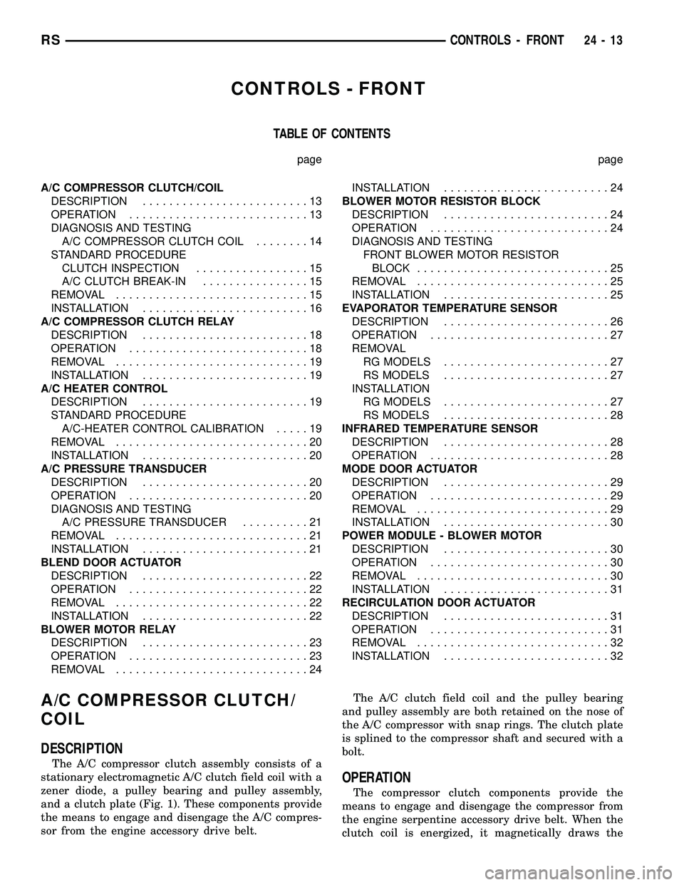
CONTROLS - FRONT
TABLE OF CONTENTS
page page
A/C COMPRESSOR CLUTCH/COIL
DESCRIPTION.........................13
OPERATION...........................13
DIAGNOSIS AND TESTING
A/C COMPRESSOR CLUTCH COIL........14
STANDARD PROCEDURE
CLUTCH INSPECTION.................15
A/C CLUTCH BREAK-IN................15
REMOVAL.............................15
INSTALLATION.........................16
A/C COMPRESSOR CLUTCH RELAY
DESCRIPTION.........................18
OPERATION...........................18
REMOVAL.............................19
INSTALLATION.........................19
A/C HEATER CONTROL
DESCRIPTION.........................19
STANDARD PROCEDURE
A/C-HEATER CONTROL CALIBRATION.....19
REMOVAL.............................20
INSTALLATION.........................20
A/C PRESSURE TRANSDUCER
DESCRIPTION.........................20
OPERATION...........................20
DIAGNOSIS AND TESTING
A/C PRESSURE TRANSDUCER..........21
REMOVAL.............................21
INSTALLATION.........................21
BLEND DOOR ACTUATOR
DESCRIPTION.........................22
OPERATION...........................22
REMOVAL.............................22
INSTALLATION.........................22
BLOWER MOTOR RELAY
DESCRIPTION.........................23
OPERATION...........................23
REMOVAL.............................24INSTALLATION.........................24
BLOWER MOTOR RESISTOR BLOCK
DESCRIPTION.........................24
OPERATION...........................24
DIAGNOSIS AND TESTING
FRONT BLOWER MOTOR RESISTOR
BLOCK.............................25
REMOVAL.............................25
INSTALLATION.........................25
EVAPORATOR TEMPERATURE SENSOR
DESCRIPTION.........................26
OPERATION...........................27
REMOVAL
RG MODELS.........................27
RS MODELS.........................27
INSTALLATION
RG MODELS.........................27
RS MODELS.........................28
INFRARED TEMPERATURE SENSOR
DESCRIPTION.........................28
OPERATION...........................28
MODE DOOR ACTUATOR
DESCRIPTION.........................29
OPERATION...........................29
REMOVAL.............................29
INSTALLATION.........................30
POWER MODULE - BLOWER MOTOR
DESCRIPTION.........................30
OPERATION...........................30
REMOVAL.............................30
INSTALLATION.........................31
RECIRCULATION DOOR ACTUATOR
DESCRIPTION.........................31
OPERATION...........................31
REMOVAL.............................32
INSTALLATION.........................32
A/C COMPRESSOR CLUTCH/
COIL
DESCRIPTION
The A/C compressor clutch assembly consists of a
stationary electromagnetic A/C clutch field coil with a
zener diode, a pulley bearing and pulley assembly,
and a clutch plate (Fig. 1). These components provide
the means to engage and disengage the A/C compres-
sor from the engine accessory drive belt.The A/C clutch field coil and the pulley bearing
and pulley assembly are both retained on the nose of
the A/C compressor with snap rings. The clutch plate
is splined to the compressor shaft and secured with a
bolt.
OPERATION
The compressor clutch components provide the
means to engage and disengage the compressor from
the engine serpentine accessory drive belt. When the
clutch coil is energized, it magnetically draws the
RSCONTROLS - FRONT24-13
Page 2168 of 2339
compressor. The bevel side of the snap ring must face
outward and both snap ring eyelets must be oriented
to the right or the left of the clutch coil dowel pin
location on the A/C compressor. Be certain that the
snap ring is fully and properly seated in the groove.
CAUTION: If the snap ring is not fully seated in the
groove it will vibrate out, resulting in a clutch fail-
ure and severe damage to the compressor front
cover.
(3) Install and securely tighten the screw that
secures the clutch coil pigtail wire connector bracket
and ground clip to the top of the compressor housing.
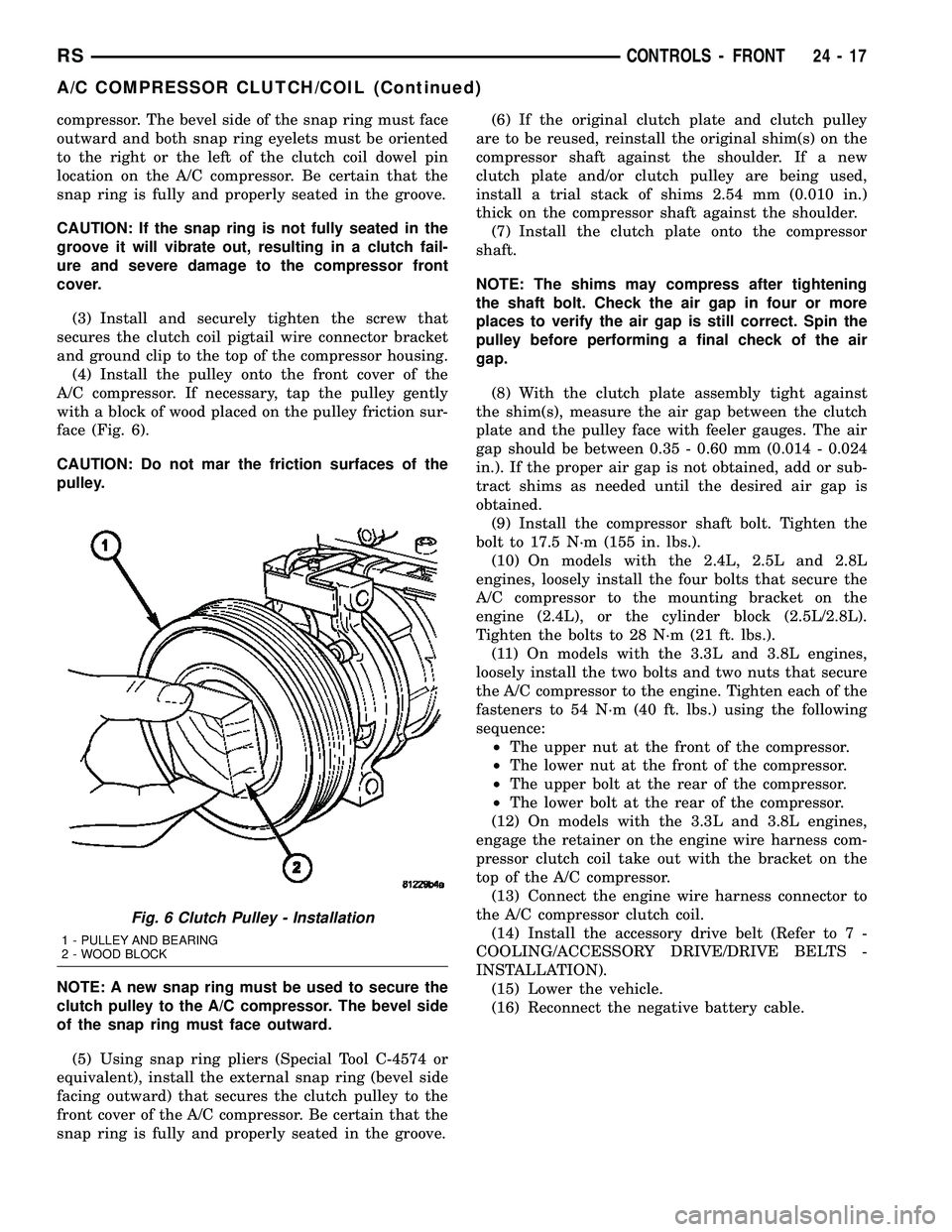
(4) Install the pulley onto the front cover of the
A/C compressor. If necessary, tap the pulley gently
with a block of wood placed on the pulley friction sur-
face (Fig. 6).
CAUTION: Do not mar the friction surfaces of the
pulley.
NOTE: A new snap ring must be used to secure the
clutch pulley to the A/C compressor. The bevel side
of the snap ring must face outward.
(5) Using snap ring pliers (Special Tool C-4574 or
equivalent), install the external snap ring (bevel side
facing outward) that secures the clutch pulley to the
front cover of the A/C compressor. Be certain that the
snap ring is fully and properly seated in the groove.(6) If the original clutch plate and clutch pulley
are to be reused, reinstall the original shim(s) on the
compressor shaft against the shoulder. If a new
clutch plate and/or clutch pulley are being used,
install a trial stack of shims 2.54 mm (0.010 in.)
thick on the compressor shaft against the shoulder.
(7) Install the clutch plate onto the compressor
shaft.
NOTE: The shims may compress after tightening
the shaft bolt. Check the air gap in four or more
places to verify the air gap is still correct. Spin the
pulley before performing a final check of the air
gap.
(8) With the clutch plate assembly tight against
the shim(s), measure the air gap between the clutch
plate and the pulley face with feeler gauges. The air
gap should be between 0.35 - 0.60 mm (0.014 - 0.024
in.). If the proper air gap is not obtained, add or sub-
tract shims as needed until the desired air gap is
obtained.
(9) Install the compressor shaft bolt. Tighten the
bolt to 17.5 N´m (155 in. lbs.).
(10) On models with the 2.4L, 2.5L and 2.8L
engines, loosely install the four bolts that secure the
A/C compressor to the mounting bracket on the
engine (2.4L), or the cylinder block (2.5L/2.8L).
Tighten the bolts to 28 N´m (21 ft. lbs.).
(11) On models with the 3.3L and 3.8L engines,
loosely install the two bolts and two nuts that secure
the A/C compressor to the engine. Tighten each of the
fasteners to 54 N´m (40 ft. lbs.) using the following
sequence:
²The upper nut at the front of the compressor.
²The lower nut at the front of the compressor.
²The upper bolt at the rear of the compressor.
²The lower bolt at the rear of the compressor.
(12) On models with the 3.3L and 3.8L engines,
engage the retainer on the engine wire harness com-
pressor clutch coil take out with the bracket on the
top of the A/C compressor.
(13) Connect the engine wire harness connector to
the A/C compressor clutch coil.
(14) Install the accessory drive belt (Refer to 7 -
COOLING/ACCESSORY DRIVE/DRIVE BELTS -
INSTALLATION).
(15) Lower the vehicle.
(16) Reconnect the negative battery cable.
Fig. 6 Clutch Pulley - Installation
1 - PULLEY AND BEARING
2 - WOOD BLOCK
RSCONTROLS - FRONT24-17
A/C COMPRESSOR CLUTCH/COIL (Continued)
Page 2175 of 2339

The blower motor relay terminals are connected to
the vehicle electrical system through a receptacle in
the Integrated Power Module (IPM). The inputs and
outputs of the blower motor relay include:
²The common feed terminal (30) receives a bat-
tery current input from the battery through a B(+)
circuit at all times.
²The coil ground terminal (85) receives a ground
input through the front/rear blower motor relay con-
trol circuit only when the FCM electronically pulls
the control circuit to ground.
²The coil battery terminal (86) receives a battery
current input from the battery through a B(+) circuit
at all times.
²The normally open terminal (87) provides a bat-
tery current output to the blower motor resistor
(manual heater-A/C control) or blower power module
(automatic heater-A/C control) through a fuse in the
IPM on the fused front blower motor relay output cir-
cuit only when the blower motor relay coil is ener-
gized.
²The normally closed terminal (87A) is not con-
nected to any circuit in this application, but provides
a battery current output only when the blower motor
relay coil is de-energized.
Refer to the appropriate wiring information for
diagnosis and testing of the micro-relay and for com-
plete HVAC wiring diagrams.
REMOVAL
(1) Disconnect and isolate the negative battery
cable.
(2) Remove the cover from the integrated power
module (IPM) (Fig. 13).
NOTE: Refer to the fuse and relay map on the inner
surface of the cover of the IPM for front blower
motor relay identification and location.
(3) Remove the front blower motor relay from the
IPM
INSTALLATION
NOTE: Refer to the fuse and relay map on the inner
surface of the cover of the integrated power module
(IPM) for front blower motor relay identification and
location.
(1) Position the front blower motor relay to the
proper receptacle in the IPM.
(2) Align the front blower motor relay terminals
with the terminal cavities in the IPM receptacle.
(3) Push down firmly on the front blower motor
relay until the terminals are fully seated in the ter-
minal cavities.
(4) Install the cover onto the IPM.(5) Reconnect the negative battery cable.
BLOWER MOTOR RESISTOR
BLOCK
DESCRIPTION
A blower motor resistor is used on this model when
it is equipped with the manual heater-A/C system.
Models equipped with the optional Automatic Tem-
perature Control (ATC) system use a blower power
module, instead of the blower motor resistor block
(Refer to 24 - HEATING & AIR CONDITIONING/
CONTROLS/POWER MODULE - DESCRIPTION).
The blower motor resistor block is mounted to the
rear of the HVAC housing, directly behind the glove
box opening in the instrument panel. The resistor
block consists of a molded plastic mounting plate
with two integral connector receptacles. Concealed
behind the mounting plate are four coiled resistor
wires contained within a protective stamped steel
cage. The blower motor resistor block is accessed for
service by removing the glove box from the instru-
ment panel.
OPERATION
The blower motor resistor block is connected to the
vehicle electrical system through a dedicated take
out and connector of the instrument panel wire har-
ness. A second connector receptacle receives the pig-
tail wire connector from the blower motor. The
blower motor resistor has multiple resistor wires,
Fig. 13 Front Blower Motor Relay
1 - INTEGRATED POWER MODULE (IPM)
2 - FRONT BLOWER MOTOR RELAY
2 - FRONT CONTROL MODULE (FCM)
24 - 24 CONTROLS - FRONTRS
BLOWER MOTOR RELAY (Continued)
Page 2176 of 2339
each of which will reduce the current flow through
the blower motor to change the blower motor speed.
The blower motor switch in the manual heater-A/C
system directs the ground path for the blower motor
through the correct resistor wire to obtain the
selected speed.
With the blower motor switch in the lowest speed
position, the ground path for the motor is applied
through all of the resistor wires. Each higher speed
selected with the blower motor switch applies the
blower motor ground path through fewer of the resis-
tor wires, increasing the blower motor speed.
The blower motor resistor cannot be adjusted or
repaired and, if faulty or damaged, it must be
replaced.
DIAGNOSIS AND TESTING
FRONT BLOWER MOTOR RESISTOR BLOCK
WARNING: ON VEHICLES EQUIPPED WITH AIR-
BAGS, DISABLE THE AIRBAG SYSTEM BEFORE
ATTEMPTING ANY STEERING WHEEL, STEERING
COLUMN, OR INSTRUMENT PANEL COMPONENT
DIAGNOSIS OR SERVICE. DISCONNECT AND ISO-
LATE THE BATTERY NEGATIVE (GROUND) CABLE,
THEN WAIT TWO MINUTES FOR THE AIRBAG SYS-
TEM CAPACITOR TO DISCHARGE BEFORE PER-
FORMING FURTHER DIAGNOSIS OR SERVICE. THIS
IS THE ONLY SURE WAY TO DISABLE THE AIRBAG
SYSTEM. FAILURE TO TAKE THE PROPER PRE-
CAUTIONS COULD RESULT IN ACCIDENTAL AIR-
BAG DEPLOYMENT AND POSSIBLE PERSONAL
INJURY.
For circuit descriptions and diagrams, refer to the
appropriate wiring information. The wiring informa-
tion includes wiring diagrams, proper wire and con-
nector repair procedures, further details on wire
harness routing and retention, as well as pin-out and
location views for the various wire harness connec-
tors, splices and grounds.
(1) Disconnect and isolate the battery negative
cable.
(2) Remove the glove box from the instrument
panel (Refer to 23 - BODY/INSTRUMENT PANEL/
GLOVE BOX - REMOVAL).
(3) Disconnect the two wire harness connectors
from the blower motor resistor block.
(4) Check for continuity between each of the
blower motor switch input terminals of the resistor
and the resistor output terminal. In each case there
should be continuity. If OK, repair the wire harness
circuits between the blower motor switch and the
blower motor resistor, blower motor or blower motorrelay as required. If not OK, replace the faulty
blower motor resistor block.
REMOVAL
WARNING: ON VEHICLES EQUIPPED WITH AIR-
BAGS, DISABLE THE AIRBAG SYSTEM BEFORE
ATTEMPTING ANY STEERING WHEEL, STEERING
COLUMN, OR INSTRUMENT PANEL COMPONENT
DIAGNOSIS OR SERVICE. DISCONNECT AND ISO-
LATE THE BATTERY NEGATIVE (GROUND) CABLE,
THEN WAIT TWO MINUTES FOR THE AIRBAG SYS-
TEM CAPACITOR TO DISCHARGE BEFORE PER-
FORMING FURTHER DIAGNOSIS OR SERVICE. THIS
IS THE ONLY SURE WAY TO DISABLE THE AIRBAG
SYSTEM. FAILURE TO TAKE THE PROPER PRE-
CAUTIONS COULD RESULT IN ACCIDENTAL AIR-
BAG DEPLOYMENT AND POSSIBLE PERSONAL
INJURY.
WARNING: THE BLOWER MOTOR RESISTOR
BLOCK MAY GET VERY HOT DURING NORMAL
OPERATION. IF THE BLOWER MOTOR WAS
TURNED ON PRIOR TO SERVICING THE BLOWER
MOTOR RESISTOR BLOCK, WAIT FIVE MINUTES
TO ALLOW THE BLOWER MOTOR RESISTORS TO
COOL BEFORE PERFORMING DIAGNOSIS OR SER-
VICE. FAILURE TO TAKE THIS PRECAUTION CAN
RESULT IN PERSONAL INJURY.
CAUTION: Do not operate the blower motor with the
blower motor resistor removed from the circuit.
Failure to take this precaution can result in vehicle
damage.
(1) Disconnect and isolate the battery negative
cable.
(2) Remove the glove box from the instrument
panel (Refer to 23 - BODY/INSTRUMENT PANEL/
GLOVE BOX - REMOVAL).
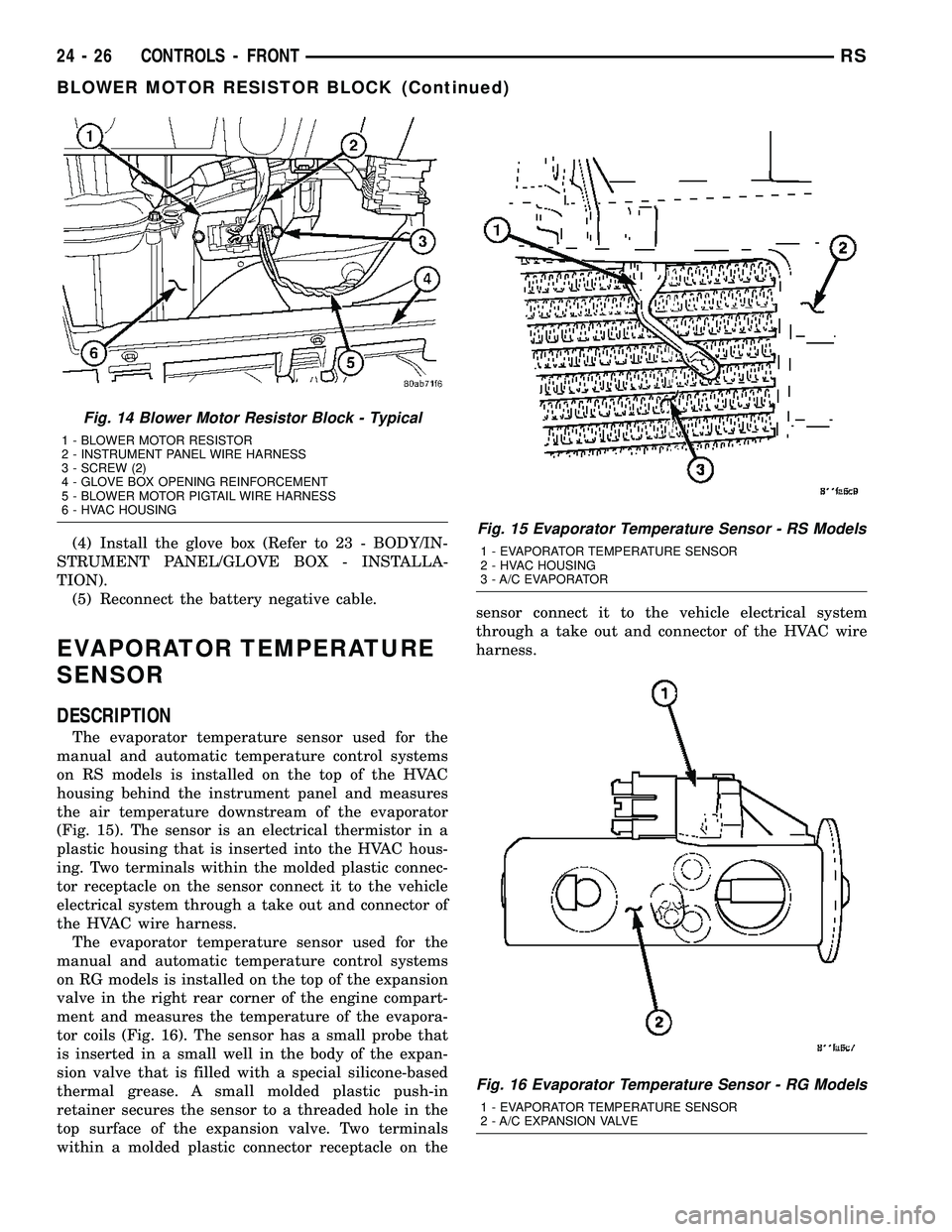
(3) Disconnect the two wire harness connectors
from the blower motor resistor block (Fig. 14).
(4) Remove the two screws that secure the blower
motor resistor block to the HVAC housing.
(5) Remove the resistor block from the HVAC
housing.
INSTALLATION
(1) Position the blower motor resistor block into
the HVAC housing.
(2) Install the two screws that secure the blower
motor resistor block to the HVAC housing. Tighten
the screws to 2 N´m (17 in. lbs.).
(3) Connect the two wire connectors to the resistor
block.
RSCONTROLS - FRONT24-25
BLOWER MOTOR RESISTOR BLOCK (Continued)
Page 2177 of 2339
(4) Install the glove box (Refer to 23 - BODY/IN-
STRUMENT PANEL/GLOVE BOX - INSTALLA-
TION).
(5) Reconnect the battery negative cable.
EVAPORATOR TEMPERATURE
SENSOR
DESCRIPTION
The evaporator temperature sensor used for the
manual and automatic temperature control systems
on RS models is installed on the top of the HVAC
housing behind the instrument panel and measures
the air temperature downstream of the evaporator
(Fig. 15). The sensor is an electrical thermistor in a
plastic housing that is inserted into the HVAC hous-
ing. Two terminals within the molded plastic connec-
tor receptacle on the sensor connect it to the vehicle
electrical system through a take out and connector of
the HVAC wire harness.
The evaporator temperature sensor used for the
manual and automatic temperature control systems
on RG models is installed on the top of the expansion
valve in the right rear corner of the engine compart-
ment and measures the temperature of the evapora-
tor coils (Fig. 16). The sensor has a small probe that
is inserted in a small well in the body of the expan-
sion valve that is filled with a special silicone-based
thermal grease. A small molded plastic push-in
retainer secures the sensor to a threaded hole in the
top surface of the expansion valve. Two terminals
within a molded plastic connector receptacle on thesensor connect it to the vehicle electrical system
through a take out and connector of the HVAC wire
harness.
Fig. 14 Blower Motor Resistor Block - Typical
1 - BLOWER MOTOR RESISTOR
2 - INSTRUMENT PANEL WIRE HARNESS
3 - SCREW (2)
4 - GLOVE BOX OPENING REINFORCEMENT
5 - BLOWER MOTOR PIGTAIL WIRE HARNESS
6 - HVAC HOUSING
Fig. 15 Evaporator Temperature Sensor - RS Models
1 - EVAPORATOR TEMPERATURE SENSOR
2 - HVAC HOUSING
3 - A/C EVAPORATOR
Fig. 16 Evaporator Temperature Sensor - RG Models
1 - EVAPORATOR TEMPERATURE SENSOR
2 - A/C EXPANSION VALVE
24 - 26 CONTROLS - FRONTRS
BLOWER MOTOR RESISTOR BLOCK (Continued)
Page 2178 of 2339
The evaporator temperature sensor cannot be
adjusted or repaired and, if faulty or damaged, it
must be replaced.
OPERATION
The evaporator temperature sensor monitors the
temperature of the conditioned air once it passes
through the A/C evaporator. The evaporator temper-
ature sensor will change its internal resistance in
response to the air temperatures it monitors and is
connected to the A/C-heater control through sensor
ground and signal circuits. As the conditioned air
temperature increases, the resistance of the evapora-
tor temperature sensor decreases and the voltage
monitored by the A/C-heater control decreases. The
external location of the evaporator temperature sen-
sor allows the sensor to be removed or installed with-
out disturbing the refrigerant in the A/C system.
The A/C-heater control uses this monitored voltage
reading as an indication of the evaporator tempera-
ture. The A/C-heater control is programmed to
respond to this input by sending electronic messages
to the powertrain control module (PCM) over the con-
troller area network (CAN) data bus. The PCM then
cycles the A/C compressor clutch as necessary to opti-
mize A/C system performance and to protect the A/C
system from evaporator freezing.
The evaporator temperature sensor cannot be
adjusted or repaired and, if faulty or damaged, it
must be replaced.
The evaporator temperature sensor is diagnosed
using the DRBIIItscan tool. Refer to Body Diagnos-
tic Procedures.
REMOVAL
RG MODELS
(1) Disconnect and isolate the battery negative
cable.
(2) Remove the air cleaner housing from the right
side of the engine compartment.
(3) Remove the windshield wiper assembly from
the vehicle (Refer to 8 - ELECTRICAL/WIPERS/
WASHERS/WIPER MODULE - REMOVAL).
(4) Remove the temperature sensor retainer from
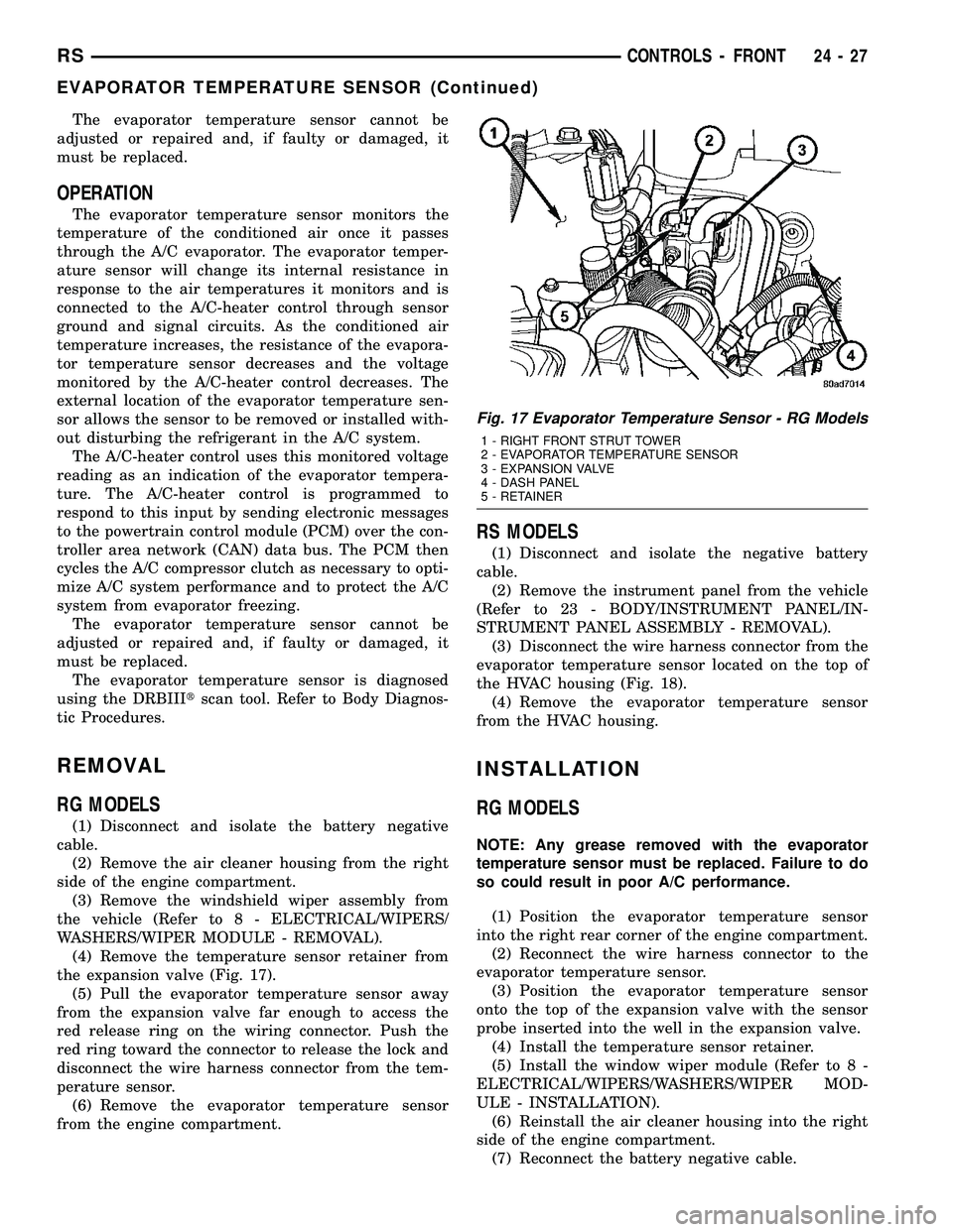
the expansion valve (Fig. 17).
(5) Pull the evaporator temperature sensor away
from the expansion valve far enough to access the
red release ring on the wiring connector. Push the
red ring toward the connector to release the lock and
disconnect the wire harness connector from the tem-
perature sensor.
(6) Remove the evaporator temperature sensor
from the engine compartment.
RS MODELS
(1) Disconnect and isolate the negative battery
cable.
(2) Remove the instrument panel from the vehicle
(Refer to 23 - BODY/INSTRUMENT PANEL/IN-
STRUMENT PANEL ASSEMBLY - REMOVAL).
(3) Disconnect the wire harness connector from the
evaporator temperature sensor located on the top of
the HVAC housing (Fig. 18).
(4) Remove the evaporator temperature sensor
from the HVAC housing.
INSTALLATION
RG MODELS
NOTE: Any grease removed with the evaporator
temperature sensor must be replaced. Failure to do
so could result in poor A/C performance.
(1) Position the evaporator temperature sensor
into the right rear corner of the engine compartment.
(2) Reconnect the wire harness connector to the
evaporator temperature sensor.
(3) Position the evaporator temperature sensor
onto the top of the expansion valve with the sensor
probe inserted into the well in the expansion valve.
(4) Install the temperature sensor retainer.
(5) Install the window wiper module (Refer to 8 -
ELECTRICAL/WIPERS/WASHERS/WIPER MOD-
ULE - INSTALLATION).
(6) Reinstall the air cleaner housing into the right
side of the engine compartment.
(7) Reconnect the battery negative cable.
Fig. 17 Evaporator Temperature Sensor - RG Models
1 - RIGHT FRONT STRUT TOWER
2 - EVAPORATOR TEMPERATURE SENSOR
3 - EXPANSION VALVE
4 - DASH PANEL
5 - RETAINER
RSCONTROLS - FRONT24-27
EVAPORATOR TEMPERATURE SENSOR (Continued)
Page 2181 of 2339
INSTALLATION
(1) Position the mode door actuator onto the HVAC
distribution housing. If necessary, rotate the actuator
slightly to align the splines on the actuator output
shaft with those in the mode door linkage.
(2) Install the two screws that secure the mode
door actuator to the distribution housing. Tighten the
screws to 2 N´m (17 in. lbs.).
(3) Connect the wire harness connector to the
mode door actuator.
(4) Install the silencer under the driver side end of
the instrument panel (Refer to 23 - BODY/INSTRU-
MENT PANEL/INSTRUMENT PANEL SILENCER -
INSTALLATION).
(5) Reconnect the negative battery cable.
(6) Perform the A/C-heater control calibration pro-
cedure (Refer to 24 - HEATING & AIR CONDITION-
ING/CONTROLS - FRONT/A/C-HEATER CONTROL
- STANDARD PROCEDURE - HEATER-A/C CON-
TROL CALIBRATION).
POWER MODULE - BLOWER
MOTOR
DESCRIPTION
A blower motor power module is used on this
model when it is equipped with the optional Auto-
matic Temperature Control (ATC) system. Models
equipped with the standard manual heater-A/C sys-
tem use a blower motor resistor block, instead of the
blower motor power module (Refer to 24 - HEATING
& AIR CONDITIONING/CONTROLS/BLOWER
MOTOR RESISTOR BLOCK - DESCRIPTION).
The blower motor power module is mounted to the
rear of the HVAC housing, directly behind the glove
box opening in the instrument panel. The module
consists of a molded plastic mounting plate with two
integral connector receptacles. Concealed behind the
mounting plate is the power module electronic cir-
cuitry and a large finned, heat sink. The blower
motor power module is accessed for service by remov-
ing the glove box from the instrument panel.
OPERATION
The blower motor power module is connected to the
vehicle electrical system through a dedicated lead
and connector from the instrument panel wire har-
ness. A second connector receptacle receives a wire
lead connector from the blower motor. The blower
motor power module allows the microprocessor-based
Automatic Temperature Control (ATC) heater-A/C
control module to calculate and provide infinitely
variable blower motor speeds based upon either man-
ual blower switch input or the ATC programming
using a Pulse Width Modulated (PWM) circuit strat-
egy. The PWM voltage is applied to a comparator cir-
cuit which compares the PWM signal voltage to the
blower motor feedback voltage. The resulting output
drives the power module circuitry, which adjusts the
voltage output received from the blower motor relay
to change or maintain the desired blower speed. The
blower motor power module is diagnosed using a
DRBIIItscan tool. Refer to Body Diagnostic Proce-
dures.
REMOVAL
WARNING: ON VEHICLES EQUIPPED WITH AIR-
BAGS, DISABLE THE AIRBAG SYSTEM BEFORE
ATTEMPTING ANY STEERING WHEEL, STEERING
COLUMN, OR INSTRUMENT PANEL COMPONENT
DIAGNOSIS OR SERVICE. DISCONNECT AND ISO-
LATE THE BATTERY NEGATIVE (GROUND) CABLE,
THEN WAIT TWO MINUTES FOR THE AIRBAG SYS-
TEM CAPACITOR TO DISCHARGE BEFORE PER-
FORMING FURTHER DIAGNOSIS OR SERVICE. THIS
IS THE ONLY SURE WAY TO DISABLE THE AIRBAG
SYSTEM. FAILURE TO TAKE THE PROPER PRE-
CAUTIONS COULD RESULT IN ACCIDENTAL AIR-
BAG DEPLOYMENT AND POSSIBLE PERSONAL
INJURY.
WARNING: THE HEAT SINK FOR THE BLOWER
MOTOR POWER MODULE MAY GET VERY HOT
DURING NORMAL OPERATION. IF THE BLOWER
MOTOR WAS TURNED ON PRIOR TO SERVICING
THE BLOWER MOTOR POWER MODULE, WAIT
FIVE MINUTES TO ALLOW THE HEAT SINK TO
COOL BEFORE PERFORMING DIAGNOSIS OR SER-
VICE. FAILURE TO TAKE THIS PRECAUTION CAN
RESULT IN PERSONAL INJURY.
24 - 30 CONTROLS - FRONTRS
MODE DOOR ACTUATOR (Continued)