2005 CHRYSLER CARAVAN ad blue
[x] Cancel search: ad bluePage 265 of 2339

CONDITION POSSIBLE CAUSES CORRECTION
2. WIRING DAMAGED 2. WITH HARNESS CONNECTED, CHECK
FOR VIDEO SIGNAL VOLTAGE AT DVD
PLAYER AND AT VIDEO SCREEN
HARNESS. PLACE KNOWN GOOD DVD
INTO DVD PLAYER. PLACE POSITIVE
LEAD OF VOLTMETER ON PIN 5 (VIDEO
SIGNAL) OF THE 12 PIN CONNECTOR.
PLACE NEGATIVE LEAD ON PIN 6 (VIDEO
GROUND). READINGS SHOULD BE
BETWEEN 0.1V TO 2V DC.
3. VIDEO SCREEN DAMAGED 3. EXCHANGE OR REPLACE VIDEO
SCREEN IF REQUIRED.
WHITE DISPLAY 1. LOW VOLTAGE 1. CHECK FOR BATTERY VOLTAGE
(9V-16V) AT DVD PLAYER 12 PIN
CONNECTOR (PIN 1-BATTERY, PIN
7-GROUND). DISPLAY WILL BE WHITE IF
VOLTAGE DROPS BELOW 6V.
2. VIDEO SCREEN DAMAGED 2. EXCHANGE OR REPLACE VIDEO
SCREEN IF REQUIRED.
DARK OR BRIGHT SPOTS
ON SCREEN1. BRIGHTNESS SETTING
REQUIRES ADJUSTMENT.1. ADJUST BRIGHTNESS SETTING OF
VIDEO SCREEN BY PRESSING BUTTONS
ON SIDE OF VIDEO SCREEN UNTIL
DESIRED LEVEL IS REACHED. START
WITH A BLACK SCREEN, THEN PRESS
BUTTON UP 16-20 TIMES. THERE ARE 64
TOTAL STEPS OF BRIGHTNESS.
BRIGHT OR DARK DISPLAY 1. VIDEO SCREEN DISPLAY
PIXEL DEFECT.1. THE ACCEPTABLE LEVEL OF DOTS ON
THE SCREEN IS (GREEN-1, RED-2) OR A
TOTAL
(GREEN+RED+BLUE+WHITE+BLACK) = 8.
REPLACE OR EXCHANGE VIDEO
SCREEN IF NECESSARY.
VIDEO SELECTIONS DO
NOT APPEAR FULL
SCREEN WIDTH1. ASPECT RATIO IS SET
INCORRECTLY.1. USING MODE BUTTON, ADJUST UNTIL
VIDEO APPEARS CORRECTLY.
2. SOME DVD'S ARE TWO
SIDED. ONE SIDE IS WIDE
SCREEN FORMAT AND THE
OTHER IS FULL SCREEN OR
THERE MAY BE A WIDE
SCREEN OR STANDARD
SCREEN FORMAT ON THE
DISC.2. ENSURE THAT DVD IS INSERTED
CORRECTLY.
8A - 6 AUDIO/VIDEORS
AUDIO/VIDEO (Continued)
Page 560 of 2339

NAVIGATION/TELECOMMUNICATION
TABLE OF CONTENTS
page page
NAVIGATION/TELECOMMUNICATION
DESCRIPTION..........................1
OPERATION............................1
DIAGNOSIS AND TESTING
TELECOMMUNICATION.................1HANDS FREE MODULE
REMOVAL.............................3
INSTALLATION..........................3
NAVIGATION/
TELECOMMUNICATION
DESCRIPTION
TELECOMMUNICATIONS
A hands-free cellular system is an available option
on this vehicle. It uses BluetoothŸ technology to pro-
vide wireless communication between the operator's
compatible cellular telephone and the vehicle's
on-board receiver.
The system uses voice recognition technology to
control operation. The incoming voice is broadcast
through the vehicle's radio speakers, automatically
overriding any other audio signals on the speakers
when the hands-free system is in use. A microphone
in the rearview mirror picks up vehicle occupant's
voices. If a call is in progress when the ignition is
switched off, the hands-free system will continue to
operate for up to 45 seconds as part of the Accessory
Relay Delay function. Thereafter, the call can con-
tinue on the hand-held telephone.
The center console front storage compartment
includes a cellular telephone holder, but the system
will communicate with a telephone that is anywhere
within the vehicle. However, covering the hand held
phone or the hands-free phone module with a metal
object may block the signal. The system will recog-
nize up to seven telephones, each of which is given a
spoken identification by the user during the setup
process. The system includes Spanish voice recogni-
tion in addition to English.
Two buttons on the rearview mirror, identified with
ISO icons, control the system: A9phone9button turns
the system on and off; a9voice recognition9(or voice
command) button prompts the hands-free system to
listen for a voice command.
OPERATION
TELECOMMUNICATION
Two buttons on the rearview mirror, identified with
ISO icons, control the system: A9phone9button turns
the system on and off; a9voice recognition9(or voice
command) button prompts the hands-free system to
listen for a voice command. The system includes the
following features:
²Phonebook - Stores telephone numbers for later
recall by name or other verbal identification, called a
voice tag, and memory location.
²Four memory locations - Home, Work, Mobile
and Pager. A maximum of 32 unique names or voice
tags may be stored at the same time, with a different
number in each of the four memory locations.
²Voice tag dialing - Dials the number associated
with a voice tag and memory location.
²Digit dialing - Dials the telephone number by
recognizing the names of the digits as they are spo-
ken.
²Receiving calls - A voice prompt notifies the user
of an incoming call. Pressing the ªphoneº button
answers the call.
²Privacy Mode - Switches the call to the hand-
held telephone and the hands-free system and back
again using the ªvoice recognitionº (or ªvoice com-
mandº) button and a voice command, if desired.
DIAGNOSIS AND TESTING
TELECOMMUNICATION
Any diagnosis of the Telecommunication sys-
tem should begin with the use of the DRB IIIt
diagnostic tool. For information on the use of
the DRB IIIt, refer to the appropriate Diagnos-
tic Service Information.
For complete circuit diagrams, refer to the appro-
priate wiring information.
RSNAVIGATION/TELECOMMUNICATION8T-1
Page 561 of 2339

WARNING: ON VEHICLES EQUIPPED WITH AIR-
BAGS, REFER TO ELECTRICAL, RESTRAINTS
BEFORE ATTEMPTING ANY STEERING WHEEL,
STEERING COLUMN, OR INSTRUMENT PANELCOMPONENT DIAGNOSIS OR SERVICE. FAILURE
TO TAKE THE PROPER PRECAUTIONS COULD
RESULT IN ACCIDENTAL AIRBAG DEPLOYMENT
AND POSSIBLE PERSONAL INJURY.
TELECOMMUNICATION SYSTEM DIAGNOSIS
CONDITION POSSIBLE CAUSE CORRECTION
Phone Not
Available1. Bluetooth phone not
paired to the system.1. Ensure that phone(s) are paired to the system.
2. Bluetooth phone not
present or turned OFF.2. Make sure paired phone is present, turned ON and that the
Bluetooth option is enabled on the phone.
3. Bluetooth phone has
low battery.3. At low battery levels, some phones will turn off Bluetooth
functionality. Ensure cellular phone is charged to an adequate
level.
Phone Pairing
Failed1. Phone does not
support Hands Free
Profile1. The Telecommunication system requires the cellular phone to
be BluetoothŸ enabled, as well as supporting the Hands Free
Profile. The customer will have to upgrade their phone to one
supporting Hands Free Profile. A list of suggested phones is
available at: http://www.chrysler.com/uconnect.
2. Phone not Bluetooth
enabled.2. The Telecommunication system requires the cellular phone to
be BluetoothŸ enabled. A list of suggested phones is available
at: http://www.chrysler.com/uconnect.
3. PIN entered on the
phone is not the same
as PIN spoken to the
system.3. The PIN spoken to the system must be the same PIN entered
into the phone.
4. Phone has reached
maximum number of
allowed devices paired.4. Remove one of the previously paired devices from it's list.
Poor Voice
Recognition1. Microphone failure 1. Using a scan tool, check for microphone fault codes.
2. Customer not waiting
for the beep before
speaking.2. Ensure customer is waiting for the system9beep9prior to
beginning the speech to be recognized.
3. Customer not
speaking in a smooth
normal manner.3. Verify that the customer is attempting to use the system with a
smooth consistent voice. The system is designed to accept
normal speech spoken at a normal tone, some people tend to
speak to a computer loud and slow, which results in reduced
performance.
4. Rear view mirror not
properly attached to
mounting.4. Mirror must be firmly mounted to the mounting location. Ensure
that mirror is tightened to the specified torque.
5. High levels of noise in
vehicle compartment5. System performance is increased when noise conditions in the
vehicle are lowered. Ideal conditions include windows closed.
6. Object interfering with
microphone input6. Verify that there is no object, hanging from the mirror, that
could be obstructing the microphone.
7. User not saying9send9
after a pager dialing
request7. User must say9send9at the end of a Pager Dialing request.
8T - 2 NAVIGATION/TELECOMMUNICATIONRS
NAVIGATION/TELECOMMUNICATION (Continued)
Page 570 of 2339

TERMINOLOGY
This is a list of terms and definitions used in the
wiring diagrams.
LHD.................Left Hand Drive Vehicles
RHD ...............Right Hand Drive Vehicles
ATX . . Automatic Transmissions-Front Wheel Drive
MTX . . . Manual Transmissions-Front Wheel Drive
AT....Automatic Transmissions-Rear Wheel Drive
MT .....Manual Transmissions-Rear Wheel Drive
SOHC...........Single Over Head Cam Engine
DOHC..........Double Over Head Cam Engine
Export . . Vehicles Built For Sale In Markets Other
Than North America
Except Export.... Vehicles Built For Sale In North
America
DESCRIPTION - CIRCUIT INFORMATION
Each wire shown in the diagrams contains a code
which identifies the main circuit, part of the main
circuit, gage of wire, and color (Fig. 4).
WIRE COLOR CODE CHART
COLOR CODE COLOR
BL BLUE
BK BLACK
BR BROWN
DB DARK BLUE
DG DARK GREEN
GY GRAY
LB LIGHT BLUE
LG LIGHT GREEN
OR ORANGE
PK PINK
RD RED
TN TAN
VT VIOLET
WT WHITE
YL YELLOW
* WITH TRACER
Fig. 4 WIRE CODE IDENTIFICATION
1 - COLOR OF WIRE (LIGHT BLUE WITH YELLOW TRACER
2 - GAGE OF WIRE (18 GAGE)
3 - PART OF MAIN CIRCUIT (VARIES DEPENDING ON
EQUIPMENT)
4 - MAIN CIRCUIT IDENTIFICATION
RS8W-01 WIRING DIAGRAM INFORMATION8W-01-5
WIRING DIAGRAM INFORMATION (Continued)
Page 976 of 2339

A/C-HEATER CONTROL C2 (MTC) - BLACK/BLUE 10 WAY
CAV CIRCUIT FUNCTION
1- -
2 C75 12DB/GY BLOWER MOTOR HIGH DRIVER
3 C73 14DB/VT (EXCEPT EXPORT) BLOWER MOTOR M2 DRIVER
3 C74 12DB/WT (EXPORT) BLOWER MOTOR M3 DRIVER
4 Z134 12BK/LG GROUND
5 C71 16DB/BR (EXPORT) BLOWER MOTOR LOW DRIVER
6- -
7- -
8- -
9 C72 16DB/OR (EXCEPT EXPORT) BLOWER MOTOR M1 DRIVER
9 C73 14DB/VT (EXPORT) BLOWER MOTOR M2 DRIVER
10 C71 16DB/BR (EXCEPT EXPORT) BLOWER MOTOR LOW DRIVER
10 C72 16DB/OR (EXPORT) BLOWER MOTOR M1 DRIVER
ACCELERATOR PEDAL POSITION SENSOR (DIESEL) - 10 WAY
CAV CIRCUIT FUNCTION
A- -
B- -
C- -
D K4 20BK/LB SENSOR GROUND
E K151 20WT LOW IDLE POSITION SWITCH SENSE
F- -
G K22 20OR/DB ACCELERATOR PEDAL POSITION SENSOR SIGNAL
NO.1
H K23 20BR/WT ACCELERATOR PEDAL POSITION SENSOR SIGNAL
NO.2
J K900 20DB/DG SENSOR GROUND
K F852 20VT/PK ACCELERATOR PEDAL POSITION SENSOR 5 VOLT
SUPPLY
ADJUSTABLE PEDALS MOTOR (EXCEPT EXPORT)-2WAY
CAV CIRCUIT FUNCTION
1 P205 18LG/DB ADJUSTABLE PEDALS MOTOR FORWARD
2 P206 18LG/TN ADJUSTABLE PEDALS MOTOR REARWARD
RS8W-80 CONNECTOR PIN-OUTS8W-80-7
Page 1005 of 2339

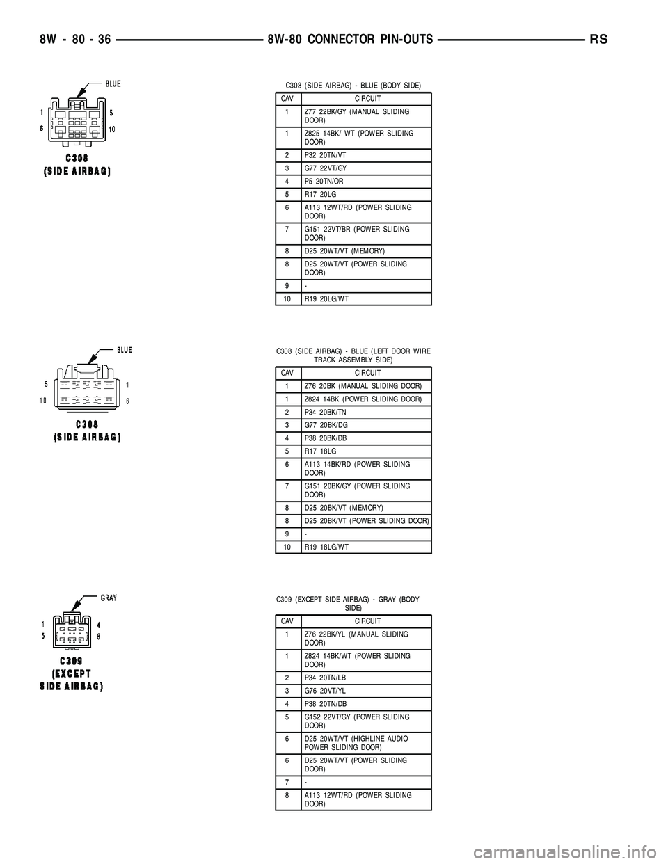
C308 (SIDE AIRBAG) - BLUE (BODY SIDE)
CAV CIRCUIT
1 Z77 22BK/GY (MANUAL SLIDING
DOOR)
1 Z825 14BK/ WT (POWER SLIDING
DOOR)
2 P32 20TN/VT
3 G77 22VT/GY
4 P5 20TN/OR
5 R17 20LG
6 A113 12WT/RD (POWER SLIDING
DOOR)
7 G151 22VT/BR (POWER SLIDING
DOOR)
8 D25 20WT/VT (MEMORY)
8 D25 20WT/VT (POWER SLIDING
DOOR)
9-
10 R19 20LG/WT
C308 (SIDE AIRBAG) - BLUE (LEFT DOOR WIRE
TRACK ASSEMBLY SIDE)
CAV CIRCUIT
1 Z76 20BK (MANUAL SLIDING DOOR)
1 Z824 14BK (POWER SLIDING DOOR)
2 P34 20BK/TN
3 G77 20BK/DG
4 P38 20BK/DB
5 R17 18LG
6 A113 14BK/RD (POWER SLIDING
DOOR)
7 G151 20BK/GY (POWER SLIDING
DOOR)
8 D25 20BK/VT (MEMORY)
8 D25 20BK/VT (POWER SLIDING DOOR)
9-
10 R19 18LG/WT
C309 (EXCEPT SIDE AIRBAG) - GRAY (BODY
SIDE)
CAV CIRCUIT
1 Z76 22BK/YL (MANUAL SLIDING
DOOR)
1 Z824 14BK/WT (POWER SLIDING
DOOR)
2 P34 20TN/LB
3 G76 20VT/YL
4 P38 20TN/DB
5 G152 22VT/GY (POWER SLIDING
DOOR)
6 D25 20WT/VT (HIGHLINE AUDIO
POWER SLIDING DOOR)
6 D25 20WT/VT (POWER SLIDING
DOOR)
7-
8 A113 12WT/RD (POWER SLIDING
DOOR)
8W - 80 - 36 8W-80 CONNECTOR PIN-OUTSRS
Page 1038 of 2339

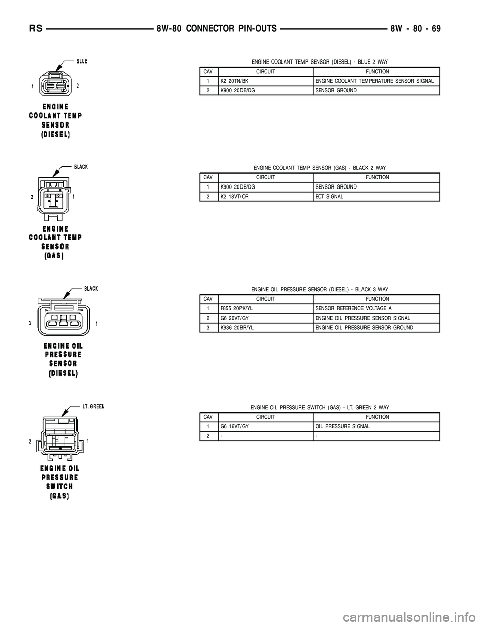
ENGINE COOLANT TEMP SENSOR (DIESEL) - BLUE 2 WAY
CAV CIRCUIT FUNCTION
1 K2 20TN/BK ENGINE COOLANT TEMPERATURE SENSOR SIGNAL
2 K900 20DB/DG SENSOR GROUND
ENGINE COOLANT TEMP SENSOR (GAS) - BLACK 2 WAY
CAV CIRCUIT FUNCTION
1 K900 20DB/DG SENSOR GROUND
2 K2 18VT/OR ECT SIGNAL
ENGINE OIL PRESSURE SENSOR (DIESEL) - BLACK 3 WAY
CAV CIRCUIT FUNCTION
1 F855 20PK/YL SENSOR REFERENCE VOLTAGE A
2 G6 20VT/GY ENGINE OIL PRESSURE SENSOR SIGNAL
3 K936 20BR/YL ENGINE OIL PRESSURE SENSOR GROUND
ENGINE OIL PRESSURE SWITCH (GAS) - LT. GREEN 2 WAY
CAV CIRCUIT FUNCTION
1 G6 16VT/GY OIL PRESSURE SIGNAL
2- -
RS8W-80 CONNECTOR PIN-OUTS8W-80-69
Page 1051 of 2339

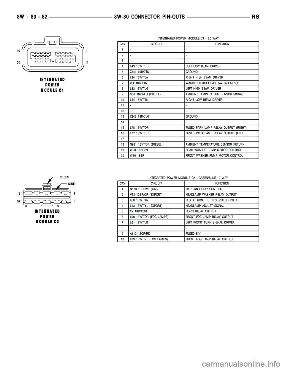
INTEGRATED POWER MODULE C1 - 20 WAY
CAV CIRCUIT FUNCTION
1- -
2- -
3- -
4 L43 18WT/DB LEFT LOW BEAM DRIVER
5 Z344 16BK/TN GROUND
6 L34 16WT/GY RIGHT HIGH BEAM DRIVER
7 W1 18BR/TN WASHER FLUID LEVEL SWITCH SENSE
8 L33 18WT/LG LEFT HIGH BEAM DRIVER
9 G31 18VT/LG (DIESEL) AMBIENT TEMPERATURE SENSOR SIGNAL
10 L44 16WT/TN RIGHT LOW BEAM DRIVER
11 - -
12 - -
13 Z343 18BK/LG GROUND
14 - -
15 L78 18WT/OR FUSED PARK LAMP RELAY OUTPUT (RIGHT)
16 L77 18WT/BR FUSED PARK LAMP RELAY OUTPUT (LEFT)
17 - -
18 G931 18VT/BR (DIESEL) AMBIENT TEMPERATURE SENSOR RETURN
19 W20 18BR/YL REAR WASHER PUMP MOTOR CONTROL
20 W10 18BR FRONT WASHER PUMP MOTOR CONTROL
INTEGRATED POWER MODULE C2 - GREEN/BLUE 10 WAY
CAV CIRCUIT FUNCTION
1 N173 18DB/VT (GAS) RAD FAN RELAY CONTROL
2 V53 12BR/OR (EXPORT) HEADLAMP WASHER RELAY OUTPUT
3 L60 18WT/TN RIGHT FRONT TURN SIGNAL DRIVER
4 L13 18WT/YL (EXPORT) HEADLAMP ADJUST SIGNAL
5 X2 18DG/OR HORN RELAY OUTPUT
6 L90 18WT/OR (FOG LAMPS) FRONT FOG LAMP RELAY OUTPUT
7 L61 18WT/LB LEFT FRONT TURN SIGNAL DRIVER
8- -
9 A112 12OR/RD FUSED B(+)
10 L89 18WT/YL (FOG LAMPS) FRONT FOG LAMP RELAY OUTPUT
8W - 80 - 82 8W-80 CONNECTOR PIN-OUTSRS