2005 CHRYSLER CARAVAN lock
[x] Cancel search: lockPage 1943 of 2339
QUARTER WINDOW
REMOVAL
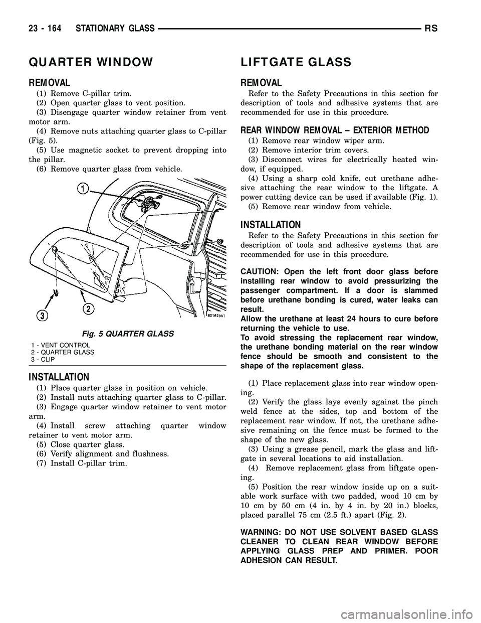
(1) Remove C-pillar trim.
(2) Open quarter glass to vent position.
(3) Disengage quarter window retainer from vent
motor arm.
(4) Remove nuts attaching quarter glass to C-pillar
(Fig. 5).
(5) Use magnetic socket to prevent dropping into
the pillar.
(6) Remove quarter glass from vehicle.
INSTALLATION
(1) Place quarter glass in position on vehicle.
(2) Install nuts attaching quarter glass to C-pillar.
(3) Engage quarter window retainer to vent motor
arm.
(4) Install screw attaching quarter window
retainer to vent motor arm.
(5) Close quarter glass.
(6) Verify alignment and flushness.
(7) Install C-pillar trim.
LIFTGATE GLASS
REMOVAL
Refer to the Safety Precautions in this section for
description of tools and adhesive systems that are
recommended for use in this procedure.
REAR WINDOW REMOVAL ± EXTERIOR METHOD
(1) Remove rear window wiper arm.
(2) Remove interior trim covers.
(3) Disconnect wires for electrically heated win-
dow, if equipped.
(4) Using a sharp cold knife, cut urethane adhe-
sive attaching the rear window to the liftgate. A
power cutting device can be used if available (Fig. 1).
(5) Remove rear window from vehicle.
INSTALLATION
Refer to the Safety Precautions in this section for
description of tools and adhesive systems that are
recommended for use in this procedure.
CAUTION: Open the left front door glass before
installing rear window to avoid pressurizing the
passenger compartment. If a door is slammed
before urethane bonding is cured, water leaks can
result.
Allow the urethane at least 24 hours to cure before
returning the vehicle to use.
To avoid stressing the replacement rear window,
the urethane bonding material on the rear window
fence should be smooth and consistent to the
shape of the replacement glass.
(1) Place replacement glass into rear window open-
ing.
(2) Verify the glass lays evenly against the pinch
weld fence at the sides, top and bottom of the
replacement rear window. If not, the urethane adhe-
sive remaining on the fence must be formed to the
shape of the new glass.
(3) Using a grease pencil, mark the glass and lift-
gate in several locations to aid installation.
(4) Remove replacement glass from liftgate open-
ing.
(5) Position the rear window inside up on a suit-
able work surface with two padded, wood 10 cm by
10 cm by 50 cm (4 in. by 4 in. by 20 in.) blocks,
placed parallel 75 cm (2.5 ft.) apart (Fig. 2).
WARNING: DO NOT USE SOLVENT BASED GLASS
CLEANER TO CLEAN REAR WINDOW BEFORE
APPLYING GLASS PREP AND PRIMER. POOR
ADHESION CAN RESULT.
Fig. 5 QUARTER GLASS
1 - VENT CONTROL
2 - QUARTER GLASS
3 - CLIP
23 - 164 STATIONARY GLASSRS
Page 1946 of 2339

(6) Install fully the entire A-pillar glass run sec-
tion by indexing the molded corner detail into the
roll frame. Slide the glass run up the A-pillar until
the rubber molded joint just touches the roll frame.
(7) Verify that the tertiary seal is on the correct
side of the roll frame prior to seating the glass run
fully onto the frame. Verify the glass runs is fully
seated for the header, and A-pillar and B-pillar
(8) Install screw attaching glass run weatherstrip
to inner door panel.
(9) Install inner belt weatherstrip.
(10) Install watershed.
(11) Push weatherstrip groove onto lip along top of
door frame.
(12) Engage clip into slot in door frame.
(13) Push weatherstrip into channel at rear of door
frame, working from the top to bottom.
(14) Install door frame closeout moldings.
(15) Install door speaker, if equipped.
(16) Install door trim panel.FRONT DOOR OUTER BELT
MOLDING
REMOVAL
(1) Remove the side view mirror. (Refer to 23 -
BODY/EXTERIOR/SIDE VIEW MIRROR -
REMOVAL)
(2) Remove door trim panel.
(3) Roll door glass down.
(4) Using a hook tool, disengage interlocking lip at
the base of the inward edge of the belt molding (Fig.
1).
(5) Remove belt molding from door.
INSTALLATION
(1) Place belt molding in position on door (Fig. 1).
NOTE: Make sure end of applique is against outer
belt.
(2) Engage interlocking lip at the base of the
inward edge of the belt molding on door panel.
(3) Install door trim panel.
Fig. 1 FRONT DOOR WEATHERSTRIP
1 - DOOR GLASS RUN WEATHERSTRIP
2 - FRONT INNER DOOR
3 - DOOR BELT OUTER WEATHERSTRIP4 - DOOR MOUNTED WEATHERSTRIP
5 - DOOR OUTER BELT WEATHERSTRIP
RSWEATHERSTRIP/SEALS23 - 167
FRONT DOOR GLASS RUN WEATHERSTRIP (Continued)
Page 1948 of 2339
SUNROOF
TABLE OF CONTENTS
page page
SUNROOF
DESCRIPTION........................169
DIAGNOSIS AND TESTING
SUNROOF DIAGNOSIS AND TESTING....169
DRAIN TUBE
REMOVAL............................172
INSTALLATION........................172
GLASS PANEL
REMOVAL............................173
INSTALLATION........................173
ADJUSTMENTS
SUNROOF GLASS PANEL ADJUSTMENT . . 173
SUNROOF ASSEMBLY
REMOVAL............................173
INSTALLATION........................173
SUNSHADE
REMOVAL............................173INSTALLATION........................173
WIND DEFLECTOR
REMOVAL............................174
INSTALLATION........................174
WATER CHANNEL
REMOVAL............................174
INSTALLATION........................174
SUNROOF MOTOR
REMOVAL............................174
INSTALLATION........................174
ADJUSTMENTS
ADJUSTMENT.......................175
SUNROOF SWITCH
REMOVAL............................176
INSTALLATION........................176
SUNROOF
DESCRIPTION
WARNING: Keep fingers and other body parts out
of sunroof opening at all times.
The sun roof features consists of: (Fig. 1)
²Sun roof glass
²Sun roof sun shade
The sunroof power sliding glass panel and sun-
shade can be positioned anywhere along its travel,
rearward of glass panel front edge.
The sunroof is electrically operated from a switch
located in the overhead console. To operate the sun-
roof the ignition switch must be in the Accessory or
On/Run position. Both switchs are a rocker style
design that open or close the sunroof. When pressing
and releasing the open button once, the sunroof will
express open to the comfort stop and the wind deflec-
tor will raise. If the button is pressed a second time,
the sunroof will continue to open to full travel unless
the button is released, at which time it will stop in
that position. Pressing and holding the close button
will close the sunroof. If the close button is released
before the glass fully closes, the sunroof will stop in
that position. The vent switch operates in a similar
manor. The sunroof will also operate for up to fifteen
minutes after the ignition key is turned off for cus-
tomer comfort and convenance while parking.
DIAGNOSIS AND TESTING
SUNROOF DIAGNOSIS AND TESTING
Refer to Sunroof Diagnostic Chart for possible
causes. Before beginning sunroof diagnostics verify
that all other power accessories are in proper operat-
ing condition. If not, a common electrical problem
may exist. Refer to Wiring Diagrams, in this publica-
tion for circuit, splice and component descriptions.
Check the condition of the circuit protection (20 amp
circuit breaker in the Junction Block). Inspect all
wiring connector pins for proper engagement and
continuity. Check for battery voltage at the power
sunroof controller, refer to Wiring Diagrams, for cir-
cuit information. If battery voltage of more than 10
volts is detected at the controller, proceed with the
following tests (the controller will not operate at less
than 10 volts).
Before beginning diagnosis for wind noise or water
leaks, verify that the problem was not caused by
releasing the control switch before the sunroof was
fully closed. The sunroof module has a water-man-
agement system. If however, the sunroof glass is in a
partial closed position, high pressure water may be
forced beyond the water management system bound-
aries and onto the headlining.
RSSUNROOF23 - 169
Page 1953 of 2339
(5) Verify that the sunshade move back and forth
properly.
(6) Cycle sunroof towards the closed position.
(7) Install glass panel (Refer to 23 - BODY/SUN-
ROOF/GLASS PANEL - INSTALLATION).
WIND DEFLECTOR
REMOVAL
(1) Fully open sunroof glass panel.
(2) Disconnect negative battery cable.
(3) Remove sunroof assembly (Refer to 23 - BODY/
SUNROOF/MODULE ASSEMBLY - REMOVAL).
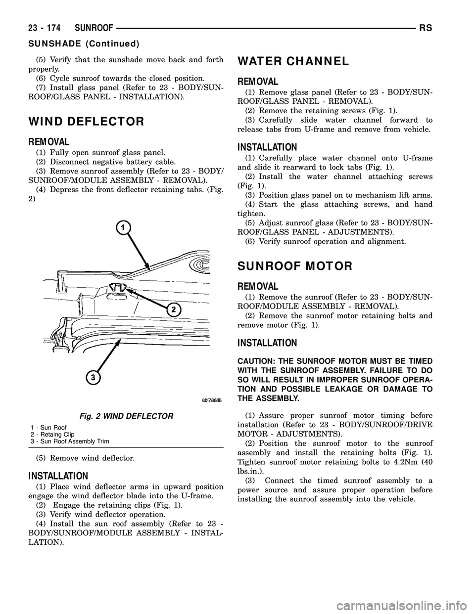
(4) Depress the front deflector retaining tabs. (Fig.
2)
(5) Remove wind deflector.
INSTALLATION
(1) Place wind deflector arms in upward position
engage the wind deflector blade into the U-frame.
(2) Engage the retaining clips (Fig. 1).
(3) Verify wind deflector operation.
(4) Install the sun roof assembly (Refer to 23 -
BODY/SUNROOF/MODULE ASSEMBLY - INSTAL-
LATION).
WATER CHANNEL
REMOVAL
(1) Remove glass panel (Refer to 23 - BODY/SUN-
ROOF/GLASS PANEL - REMOVAL).
(2) Remove the retaining screws (Fig. 1).
(3) Carefully slide water channel forward to
release tabs from U-frame and remove from vehicle.
INSTALLATION
(1) Carefully place water channel onto U-frame
and slide it rearward to lock tabs (Fig. 1).
(2) Install the water channel attaching screws
(Fig. 1).
(3) Position glass panel on to mechanism lift arms.
(4) Start the glass attaching screws, and hand
tighten.
(5) Adjust sunroof glass (Refer to 23 - BODY/SUN-
ROOF/GLASS PANEL - ADJUSTMENTS).
(6) Verify sunroof operation and alignment.
SUNROOF MOTOR
REMOVAL
(1) Remove the sunroof (Refer to 23 - BODY/SUN-
ROOF/MODULE ASSEMBLY - REMOVAL).
(2) Remove the sunroof motor retaining bolts and
remove motor (Fig. 1).
INSTALLATION
CAUTION: THE SUNROOF MOTOR MUST BE TIMED
WITH THE SUNROOF ASSEMBLY. FAILURE TO DO
SO WILL RESULT IN IMPROPER SUNROOF OPERA-
TION AND POSSIBLE LEAKAGE OR DAMAGE TO
THE ASSEMBLY.
(1) Assure proper sunroof motor timing before
installation (Refer to 23 - BODY/SUNROOF/DRIVE
MOTOR - ADJUSTMENTS).
(2) Position the sunroof motor to the sunroof
assembly and install the retaining bolts (Fig. 1).
Tighten sunroof motor retaining bolts to 4.2Nm (40
lbs.in.).
(3) Connect the timed sunroof assembly to a
power source and assure proper operation before
installing the sunroof assembly into the vehicle.
Fig. 2 WIND DEFLECTOR
1 - Sun Roof
2 - Retaing Clip
3 - Sun Roof Assembly Trim
23 - 174 SUNROOFRS
SUNSHADE (Continued)
Page 1954 of 2339
ADJUSTMENTS
ADJUSTMENT
CAUTION: THE IS NO ADJUSTMENT AVAILABLE
FOR A NORMALLY OPERATING SUNROOF. THIS
PROCEDURE IS USE TO SET SUNROOF MOTOR TO
SUNROOF ASSEMBLY TIMING.
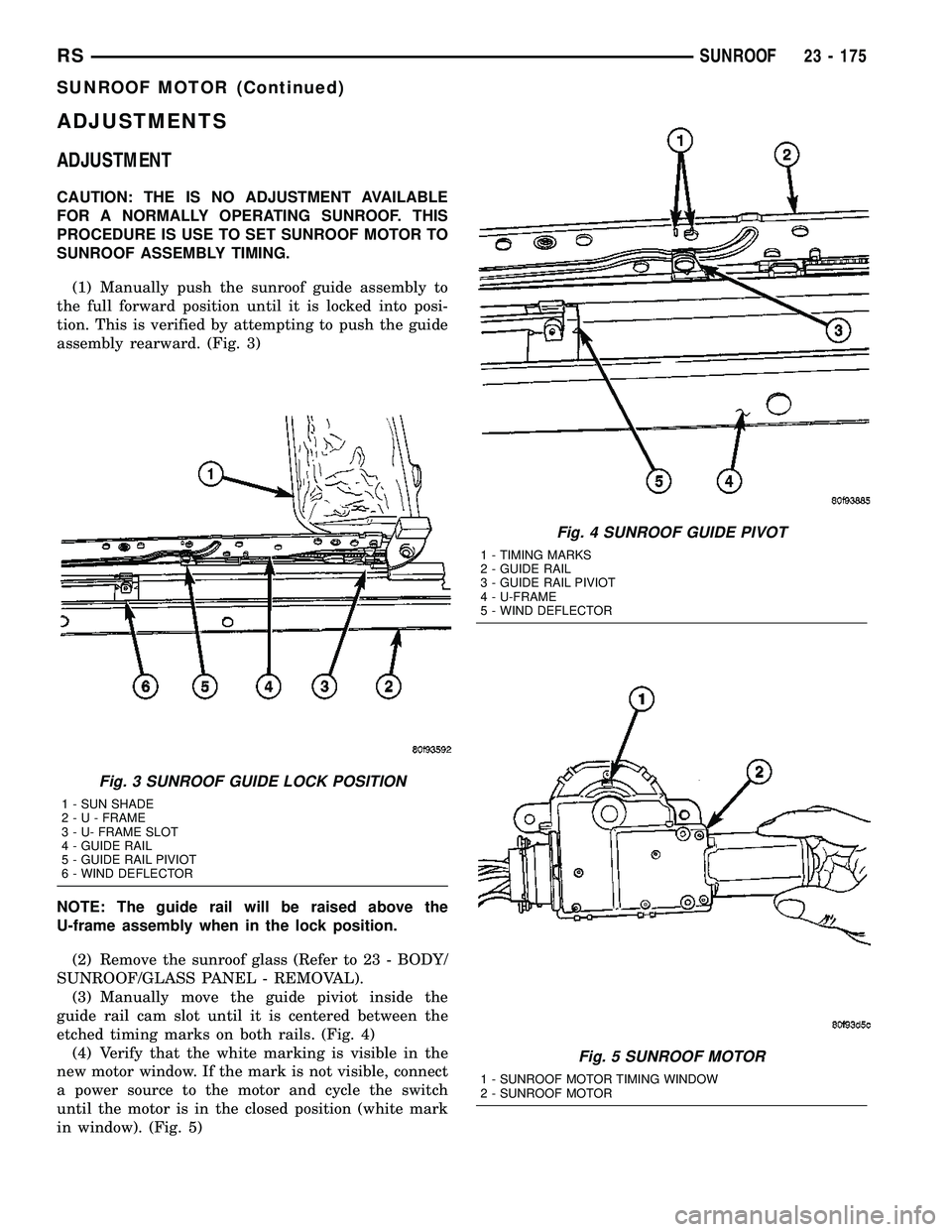
(1) Manually push the sunroof guide assembly to
the full forward position until it is locked into posi-
tion. This is verified by attempting to push the guide
assembly rearward. (Fig. 3)
NOTE: The guide rail will be raised above the
U-frame assembly when in the lock position.
(2) Remove the sunroof glass (Refer to 23 - BODY/
SUNROOF/GLASS PANEL - REMOVAL).
(3) Manually move the guide piviot inside the
guide rail cam slot until it is centered between the
etched timing marks on both rails. (Fig. 4)
(4) Verify that the white marking is visible in the
new motor window. If the mark is not visible, connect
a power source to the motor and cycle the switch
until the motor is in the closed position (white mark
in window). (Fig. 5)
Fig. 3 SUNROOF GUIDE LOCK POSITION
1 - SUN SHADE
2-U-FRAME
3 - U- FRAME SLOT
4 - GUIDE RAIL
5 - GUIDE RAIL PIVIOT
6 - WIND DEFLECTOR
Fig. 4 SUNROOF GUIDE PIVOT
1 - TIMING MARKS
2 - GUIDE RAIL
3 - GUIDE RAIL PIVIOT
4 - U-FRAME
5 - WIND DEFLECTOR
Fig. 5 SUNROOF MOTOR
1 - SUNROOF MOTOR TIMING WINDOW
2 - SUNROOF MOTOR
RSSUNROOF23 - 175
SUNROOF MOTOR (Continued)
Page 2152 of 2339
HEATING & AIR CONDITIONING
TABLE OF CONTENTS
page page
HEATING & AIR CONDITIONING
DESCRIPTION
ENGINE COOLING SYSTEM
REQUIREMENTS.......................1
HEATER AND AIR CONDITIONER..........1
MANUAL SINGLE ZONE.................2
MANUAL DUAL ZONE...................2
MANUAL THREE ZONE..................2
AUTOMATIC TEMPERATURE CONTROL....3
OPERATION
HEATER AND AIR CONDITIONER..........4
MANUAL SINGLE ZONE.................4
MANUAL DUAL ZONE...................5
MANUAL THREE ZONE..................5AUTOMATIC TEMPERATURE CONTROL....5
DIAGNOSIS AND TESTING
A/C COOL DOWN TEST.................6
A/C PERFORMANCE TEST...............7
HEATER PERFORMANCE TEST..........10
SPECIFICATIONS
A/C SYSTEM.........................11
CONTROLS - FRONT.....................13
CONTROLS - REAR......................33
DISTRIBUTION - FRONT...................42
DISTRIBUTION - REAR....................56
PLUMBING - FRONT.....................64
PLUMBING - REAR......................98
CABIN HEATER........................113
HEATING & AIR
CONDITIONING
DESCRIPTION
ENGINE COOLING SYSTEM REQUIREMENTS
To maintain the performance level of the heating,
ventilation and air conditioning (HVAC) system, the
engine cooling system must be properly maintained.
The use of a bug screen is not recommended. Any
obstructions in front of the radiator or condenser will
reduce the performance of the air conditioning and
engine cooling systems.
The engine cooling system includes the radiator,
thermostat, radiator hoses and the engine coolant
pump. Refer to Cooling for more information before
opening or attempting any service to the engine cool-
ing system.
HEATER AND AIR CONDITIONER
A manually controlled single zone type heating-air
conditioning system, manually controlled dual zone
type heating-air conditioning system, manually con-
trolled three zone type heating-air conditioning sys-
tem or an automatic controlled three zone type
heating-air conditioning system is available on this
model.
All vehicles are equipped with a common heater,
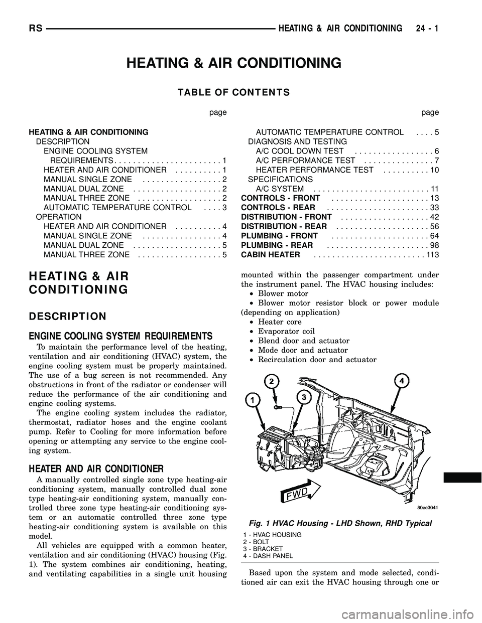
ventilation and air conditioning (HVAC) housing (Fig.
1). The system combines air conditioning, heating,
and ventilating capabilities in a single unit housingmounted within the passenger compartment under
the instrument panel. The HVAC housing includes:
²Blower motor
²Blower motor resistor block or power module
(depending on application)
²Heater core
²Evaporator coil
²Blend door and actuator
²Mode door and actuator
²Recirculation door and actuator
Based upon the system and mode selected, condi-
tioned air can exit the HVAC housing through one or
Fig. 1 HVAC Housing - LHD Shown, RHD Typical
1 - HVAC HOUSING
2 - BOLT
3 - BRACKET
4 - DASH PANEL
RSHEATING & AIR CONDITIONING24-1
Page 2157 of 2339
defogger function will be active for 10 minutes and
can be turned off by a switch press. The defogger will
function while the control is in the ON mode.
²FAN/MODE± The Fan and Mode knobs have
17 manual selectable positions. Manually changing
either of the rotary knobs for mode or fan speed set-
tings makes control of that blower motor manual. If
only one is changed manually, the other remains
under automatic control. Pressing the HI-AUTO/LO-
AUTO rocker switch restores full automatic control.
²BLOWER DELAY TIMER± The word DELAY
is displayed at start-up to signify that the system is
waiting so that cold air will not be blowing. This tells
the operator that it is unnecessary to turn the sys-
tem off, raise the temperature setting or turn the fan
speed setting down to prevent cold air from blowing.
A countdown in minutes and seconds until the engine
is warm enough to begin delivering heat to the pas-
sengers alternates with the DELAY message at 25
second intervals. This countdown is based on actual
measurement of the rate of engine coolant tempera-
ture change. During the delay time, mix mode is
selected and the fan operates at a low speed to keep
the windshield fog free.
²REAR CONTROL (Three-Zone only)± When
the Rear System control knob is moved to the OFF
position, there will be a delay of approximately 1 sec-
ond before the system actually turns off. This delay
is to prevent an undesired blower dropout if the knob
is moved through OFF to the other selections.
REAR CONTROL PANEL ± THREE ZONE ATC
SYSTEM
Primary control of the rear compartment heating-
A/C system for the Three-Zone ATC system is in the
instrument panel center stack. This control allows
the driver to turn the rear heating-A/C system off, or
allows the intermediate seat occupants control of the
rear system by switching to the REAR position, or
provides fully automatic control based on the temper-
ature setting shown on the front control display.
²REAR CONTROL± Selecting automatic control
of the rear unit at the instrument panel, illuminates
a Locked Padlock in the rear control panel display.
Selecting REAR activates the rear control panel and
the Padlock then appears unlocked.
²FAN KNOB± The rear fan control has Off and
AUTO positions and a range of manual speed set-
tings that override the AUTO setting.
²MODE KNOB± The mode control allows inter-
mediate seat occupants to manually override the
automatic mode and select any balance of air flow
between overhead and floor outlets from full over-
head to full floor.
²SET TEMP± The rear set temp control will
operate identical to the front controls. If the frontcontrol rear set temp button is pressed simulta-
neously with the rear control head, then the front
control head press events shall have priority, i.e. if
the front user presses Rear Set Temp down and the
rear user presses Set Temp up, then the rear set
temp will decrease.
DIAGNOSIS AND TESTING
A/C COOL DOWN TEST
The heater-A/C control module can perform an A/C
cool down test, which is a test performed during the
manufacturing process to confirm that the air condi-
tioning system is performing satisfactorily. This test
can also provide a quick confirmation of air condi-
tioning system performance to the service technician.
If the test is completed satisfactorily, no further ser-
vice is required. If the test is failed, proceed to the
A/C Performance Test to confirm the A/C system is
operating properly, or use a DRBIIItscan tool to
diagnose the A/C system control and distribution sys-
tems. Refer to the appropriate diagnostic informa-
tion.
MANUAL TEMPERATURE CONTROL
The front blower speed and rear blower speed (if
equipped with rear HVAC) must be set to High and
the evaporator temperature sensor must be greater
than 13É C (55É F) or the test will fail immediately.
The test is activated by depressing the A/C and Rear
Wipe/Wash buttons simultaneously and holding them
depressed for no less than five seconds. The Rear
Wipe/Wash and A/C LEDs will blink on and off until
the test is complete. If the LEDs stop blinking before
two minutes, then the cool down test has been com-
pleted successfully. If the two minutes expire without
the expansion valve temperature reaching -6É C (20É
F) less than the outside air temperature, then the
cool down test has been failed and further A/C sys-
tem diagnosis is required. If the test is failed, the
LEDs will continue to blink until the vehicle has
been driven for greater than 13 km (8 miles).
AUTOMATIC TEMPERATURE CONTROL
The ambient air temperature in the room where
the vehicle will be tested must be a minimum of 21É
C (70ÉF) for this test. The test is activated by
depressing the A/C and PWR buttons simultaneously
and holding them depressed for no less than four sec-
onds. The snowflake icon and the DELAY text in the
ATC display will blink on and off alternately until
the test is complete. If the snowflake icon and the
DELAY text stop blinking before two minutes, then
the cool down test has been completed successfully. If
the two minutes expire without the evaporator tem-
perature reaching -6É C (20É F) less than the evapo-
24 - 6 HEATING & AIR CONDITIONINGRS
HEATING & AIR CONDITIONING (Continued)
Page 2162 of 2339
TEMPERATURE CONTROL
If the heater outlet air temperature cannot be
adjusted with the temperature control knob on the
A/C-heater control panel, the following could require
service:
²Blend door binding.
²Faulty blend door actuator.
²Faulty A/C-heater control.
²Faulty related wiring harness or connectors.²Improper engine coolant temperature.
SPECIFICATIONS
A/C SYSTEM
The R-134a refrigerant system charge capacity for
this vehicle can be found on the underhood Specifica-
tion Label.
SYSTEM SPECIFICATIONS
Item Description Notes
A/C Compressor Denso 10S17 ± 2.4L/2.5L/2.8L/3.3L
without rear A/C
Denso 10S20 ± 3.3L/3.8L with rear
A/CND-8 PAG Oil
Freeze±up Control Evaporator temperature sensor HVAC housing mounted (RS models),
Evaporator mounted (RG models) - input to
A/C-heater control module
Low PSI Control A/C pressure transducer Liquid line mounted - input to Powertrain Control
Module (PCM) - PCM opens compressor clutch
relay above 200 kPa (29 psi)
High PSI Control A/C pressure transducer Liquid line mounted - input to PCM - PCM
opens compressor clutch relay below 3100 kPa
(450 psi)
High Pressure relief valve Compressor mounted - opens above 3445-4135
kPa (500-600 psi), closes below 2756 kPa (400
psi)
Compressor Clutch Coil
DrawDenso 10S17 ± 3.3 amps @ 12V
0.5V @ 21É C (70É F)
Denso 10S20 ± 2.2 amps @ 12V
0.5V @ 21É C (70É F)
Compressor Clutch Air
Gap0.35 - 0.60 mm (0.014 - 0.024 in.)
TORQUE SPECIFICATIONS
Description N´m Ft. Lbs. In. Lbs.
A/C Compressor Shaft Bolt 17.5 ± 155
A/C Compressor Mounting Bolts (2.4L/2.5L/2.8L) 28 21 ±
A/C Compressor Mounting Bolts (3.3L/3.8L) 54 40 ±
A/C Compressor Mounting Bracket Bolts (2.4L) 54 40 ±
A/C Condenser Mounting Bracket Screws 5 ± 45
A/C Expansion Valve Screws 11 ± 97
A/C-Heater Control Screws 2 ± 17
Blend Door Actuator Screws 2 ± 17
Blower Motor Screws 2 ± 17
Blower Motor Power Module Screws (ATC) 2 ± 17
Blower Motor Resistor Block Screws (MTC) 2 ± 17
Center Bezel Outlet Screws 2 ± 17
RSHEATING & AIR CONDITIONING24-11
HEATING & AIR CONDITIONING (Continued)