Page 4 of 92
Downloaded from www.Manualslib.com manuals search engine 4
Overview
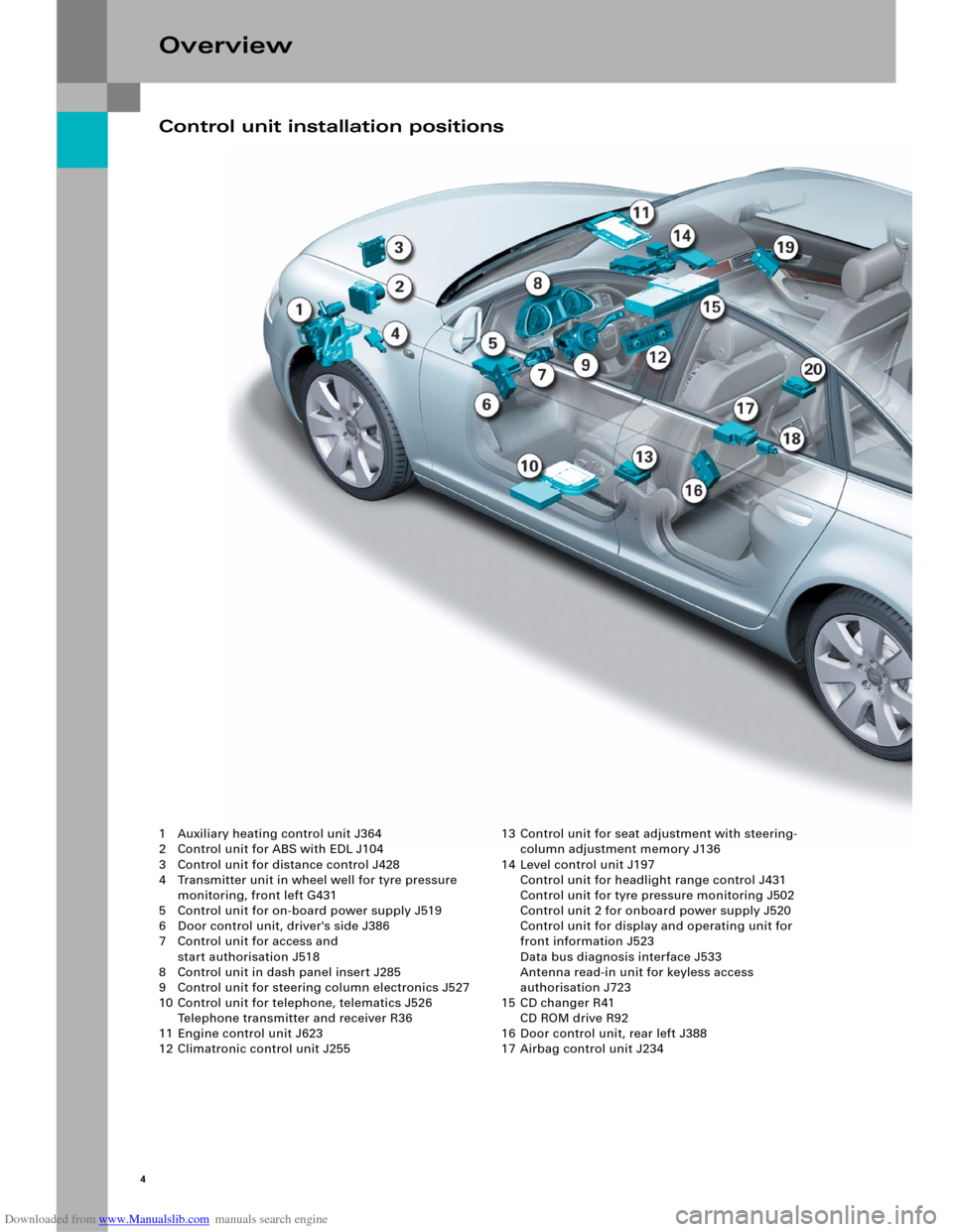
1 Auxiliary heating control unit J364
2 Control unit for ABS with EDL J104
3 Control unit for distance control J428
4 Transmitter unit in wheel well for tyre pressure
monitoring, front left G431
5 Control unit for on-board power supply J519
6 Door control unit, driver's side J386
7 Control unit for access and
start authorisation J518
8 Control unit in dash panel insert J285
9 Control unit for steering column electronics J527
10 Control unit for telephone, telematics J526
Telephone transmitter and receiver R36
11 Engine control unit J623
12 Climatronic control unit J25513 Control unit for seat adjustment with steering-
column adjustment memory J136
14 Level control unit J197
Control unit for headlight range control J431
Control unit for tyre pressure monitoring J502
Control unit 2 for onboard power supply J520
Control unit for display and operating unit for
front information J523
Data bus diagnosis interface J533
Antenna read-in unit for keyless access
authorisation J723
15 CD changer R41
CD ROM drive R92
16 Door control unit, rear left J388
17 Airbag control unit J234
Control unit installation positions
Page 6 of 92
Downloaded from www.Manualslib.com manuals search engine 6
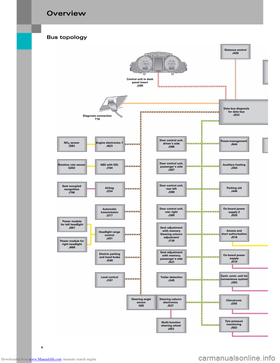
Bus topology
Overview
NOX sensor
J583
Rotation rate sensor
G202
Seat occupied
recognition
J706
Power module
for left headlight
J667
Power m odule for
right headlight
J668
Level control
J197 Electric parking
and hand brake
J540 Headlight range
control
J431 Automatic
transmission
J217 Airbag
J234 ABS with EDL
J104 Engine electronics 1
J623 Diagnosis connection
T16Control unit in dash
panel insert
J285Distance control
J428
Data bus diagnosis
for data bus
J533
Door control unit,
driver’s side
J386
Door control unit,
passenger’s side
J387
Door control unit,
rear left
J388
Door control unit,
rear right
J389
Seat adjustment
with memory
Steering column
adjustment
J136
Seat adjustment
with memory,
passenger’s side
J521
Trailer detection
J345
Steering column
electronics
J527
Multi-function
steering wheel
J453 Steering-angle
sensor
G85Power management
J644
Auxiliary heating
J364
Parking aid
J446
On-board power
supply 2
J520
Access and
start authorisation
J518
On-board power
supply
J519
Centr. contr. unit for
convenience system
J393
Climatronic
J255
Tyre pressure
monitoring
J502
Page 14 of 92
Downloaded from www.Manualslib.com manuals search engine 16
The Advanced Key system was introduced with the
Audi A8 '03 and has been fundamentally revised for
the Audi A6 ’05.
The most important new feature is that the control
unit for access and start authorisation has been
combined with the actuator for steering column
locking.
Convenience electrics
System overview
Page 17 of 92
Downloaded from www.Manualslib.com manuals search engine 19
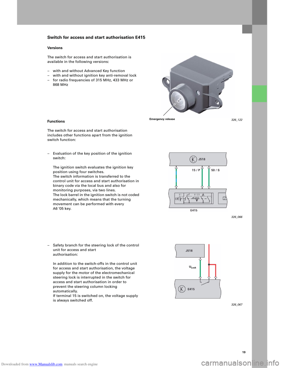
Ve rs i on s
The switch for access and start authorisation is
available in the following versions:
– with and without Advanced Key function
– with and without ignition key anti-removal lock
– for radio frequencies of 315 MHz, 433 MHz or
868 MHz
Functions
The switch for access and start authorisation
includes other functions apart from the ignition
switch function:
– Evaluation of the key position of the ignition
switch:
The ignition switch evaluates the ignition key
position using four switches.
The switch information is transferred to the
control unit for access and start authorisation in
binary code via the local bus and also for
monitoring purposes, via two lines.
The lock barrel in the ignition switch is not coded
mechanically, which means that the turning
movement can be performed with every
A6 '05 key.
– Safety branch for the steering lock of the control
unit for access and start
authorisation:
In addition to the switch-offs in the control unit
for access and start authorisation, the voltage
supply for the motor of the electromechanical
steering lock is interrupted in the switch for
access and start authorisation in order to
prevent the steering column locking
automatically.
If terminal 15 is switched on, the voltage supply
is always switched off.
326_066
326_067
Switch for access and start authorisation E415
ULock
326_122Emergency release
Page 19 of 92
Downloaded from www.Manualslib.com manuals search engine 21
The electromechanical steering column lock was
integrated into the control unit for access and start
authorisation.
Functions
– Terminal control:
The control unit for access and start
authorisation puts the information about
terminal 15, 75x, 50, S and P on
CAN Convenience.
The control unit also activates the relays for
terminal 15 and 75x and passes the start request
signal on to the engine control unit.– Locking the steering column:
The motor and gears for locking the steering
column are integrated into the control unit for
access and start authorisation.
The position of the lock is checked using two
integrated micro switches. Terminal 15 is only
switched on after the steering is unlocked fully.
– Immobiliser and component protection:
The control unit is the master for these
functions.
Control unit for access and start authorisation J518
326_095
Page 27 of 92
Downloaded from www.Manualslib.com manuals search engine 29
1 The driver presses the button for access and
start authorisation E408 down fully. The button
sends the information about "Ignition on" and
"Engine start" both to the switch for access and
start authorisation E415 and to the control unit
for access and start authorisation J518.
2 The switch for access and start authorisation
passes the information from the button on to the
control unit for access and start authorisation via
the data lead. The two button information
messages are compared there.
3 The control unit J518 sends a key query to the
antenna read-in unit for keyless access
authorisation J723.
The antenna read-in unit sends a signal to the
vehicle key via all the antennae for access and
start authorisation.
4 Based on the signals, the vehicle key determines
the position in the vehicle and sends its
information to the antenna for central locking
and anti-theft warning system R47.
5 The antenna for central locking and anti-theft
warning system receives the information.
The switch for access and start authorisation
E415 passes the information on to the control
unit for access and start authorisation, which
then evaluates it. 6 Based on the key evaluation, the S contact is
sent to CAN Convenience and the steering is
unlocked.
7 As soon as the steering is fully unlocked,
terminal 15 is switched on.
8 Once terminal 15 has been switched on, data is
exchanged between the engine control unit and
the control unit for access and start
authorisation via the CAN bus. The immobiliser is
then deactivated.
9 The control unit for access and start
authorisation sends the "Start request" signal to
the engine control unit. The engine control unit
checks whether the clutch is depressed or
whether P or N is selected in the case of an
automatic gearbox and then performs the fully
automatic engine start.
Page 32 of 92
Downloaded from www.Manualslib.com manuals search engine 34
Adaptive light
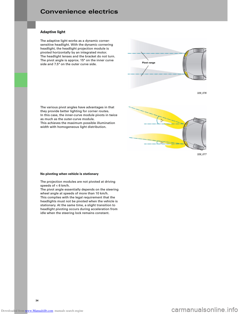
The adaptive light works as a dynamic corner-
sensitive headlight. With the dynamic cornering
headlight, the headlight projection module is
pivoted horizontally by an integrated motor.
The headlight lenses and the bracket do not turn.
The pivot angle is approx. 15° on the inner curve
side and 7.5° on the outer curve side.
The various pivot angles have advantages in that
they provide better lighting for corner routes.
In this case, the inner-curve module pivots in twice
as much as the outer-curve module.
This achieves the maximum possible illumination
width with homogeneous light distribution.
No pivoting when vehicle is stationary
The projection modules are not pivoted at driving
speeds of < 6 km/h.
The pivot angle essentially depends on the steering
wheel angle at speeds of more than 10 km/h.
This complies with the legal requirement that the
headlights must not be pivoted when the vehicle is
stationary. At the same time, a slight transition to
headlight pivoting occurs during acceleration from
idle when the steering lock remains constant.
Convenience electrics
326_077
Pivot range
326_076
Page 33 of 92
Downloaded from www.Manualslib.com manuals search engine 35
Internal structure
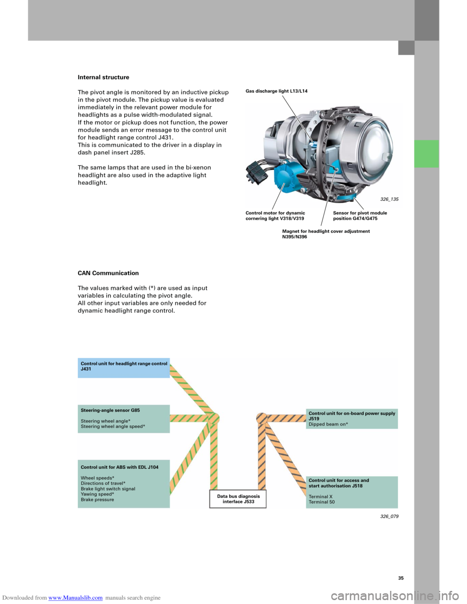
The pivot angle is monitored by an inductive pickup
in the pivot module. The pickup value is evaluated
immediately in the relevant power module for
headlights as a pulse width-modulated signal.
If the motor or pickup does not function, the power
module sends an error message to the control unit
for headlight range control J431.
This is communicated to the driver in a display in
dash panel insert J285.
The same lamps that are used in the bi-xenon
headlight are also used in the adaptive light
headlight.
CAN Communication
The values marked with (*) are used as input
variables in calculating the pivot angle.
All other input variables are only needed for
dynamic headlight range control.
326_079 Data bus diagnosis
interface J533 Co n t ro l u n it fo r h e a d li g h t ra n g e c o n t ro l
J431
Steering-angle sensor G85
Steering wheel angle*
Steering wheel angle speed*
Control unit for ABS with EDL J104
Wheel speeds*
Directions of travel*
Brake light switch signal
Yawing speed*
Brake pressureControl unit for on-board power supply
J519
Dipped beam on*
Control unit for access and
start authorisation J518
Te r m i n a l X
Te r m i n a l 5 0
Gas discharge light L13/L14
326_135
Control motor for dynamic
cornering light V318/V319
Magnet for headlight cover adjustment
N395/N396Sensor for pivot module
position G474/G475