2005 AUDI A6 power steering
[x] Cancel search: power steeringPage 4 of 92
Downloaded from www.Manualslib.com manuals search engine 4
Overview
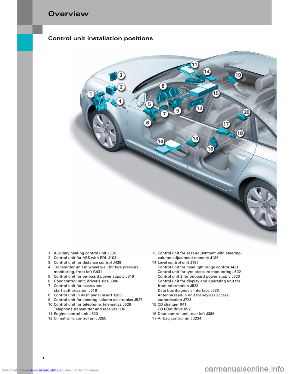
1 Auxiliary heating control unit J364
2 Control unit for ABS with EDL J104
3 Control unit for distance control J428
4 Transmitter unit in wheel well for tyre pressure
monitoring, front left G431
5 Control unit for on-board power supply J519
6 Door control unit, driver's side J386
7 Control unit for access and
start authorisation J518
8 Control unit in dash panel insert J285
9 Control unit for steering column electronics J527
10 Control unit for telephone, telematics J526
Telephone transmitter and receiver R36
11 Engine control unit J623
12 Climatronic control unit J25513 Control unit for seat adjustment with steering-
column adjustment memory J136
14 Level control unit J197
Control unit for headlight range control J431
Control unit for tyre pressure monitoring J502
Control unit 2 for onboard power supply J520
Control unit for display and operating unit for
front information J523
Data bus diagnosis interface J533
Antenna read-in unit for keyless access
authorisation J723
15 CD changer R41
CD ROM drive R92
16 Door control unit, rear left J388
17 Airbag control unit J234
Control unit installation positions
Page 6 of 92
Downloaded from www.Manualslib.com manuals search engine 6
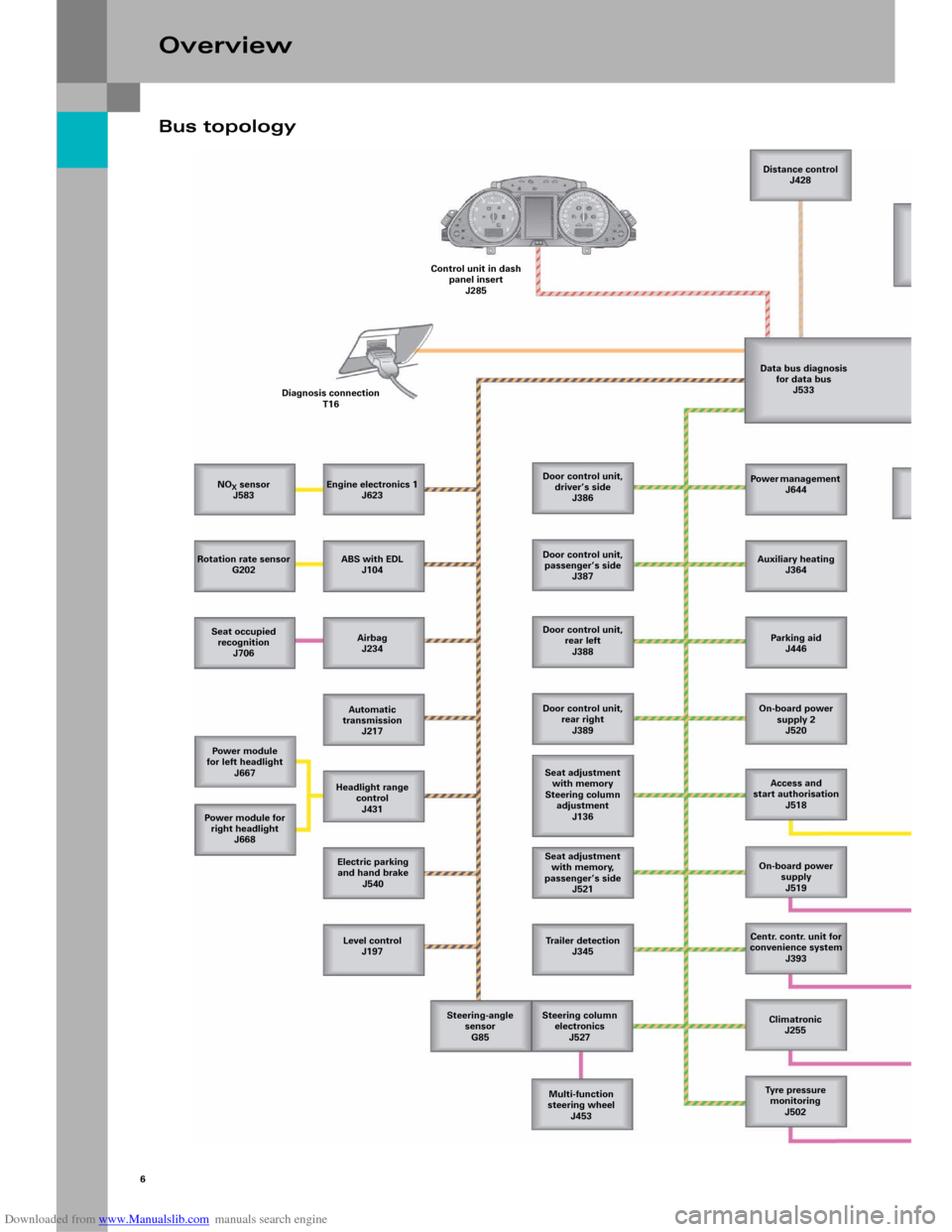
Bus topology
Overview
NOX sensor
J583
Rotation rate sensor
G202
Seat occupied
recognition
J706
Power module
for left headlight
J667
Power m odule for
right headlight
J668
Level control
J197 Electric parking
and hand brake
J540 Headlight range
control
J431 Automatic
transmission
J217 Airbag
J234 ABS with EDL
J104 Engine electronics 1
J623 Diagnosis connection
T16Control unit in dash
panel insert
J285Distance control
J428
Data bus diagnosis
for data bus
J533
Door control unit,
driver’s side
J386
Door control unit,
passenger’s side
J387
Door control unit,
rear left
J388
Door control unit,
rear right
J389
Seat adjustment
with memory
Steering column
adjustment
J136
Seat adjustment
with memory,
passenger’s side
J521
Trailer detection
J345
Steering column
electronics
J527
Multi-function
steering wheel
J453 Steering-angle
sensor
G85Power management
J644
Auxiliary heating
J364
Parking aid
J446
On-board power
supply 2
J520
Access and
start authorisation
J518
On-board power
supply
J519
Centr. contr. unit for
convenience system
J393
Climatronic
J255
Tyre pressure
monitoring
J502
Page 33 of 92
Downloaded from www.Manualslib.com manuals search engine 35
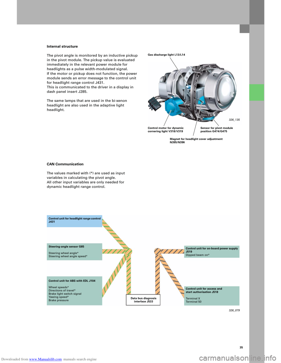
Internal structure
The pivot angle is monitored by an inductive pickup
in the pivot module. The pickup value is evaluated
immediately in the relevant power module for
headlights as a pulse width-modulated signal.
If the motor or pickup does not function, the power
module sends an error message to the control unit
for headlight range control J431.
This is communicated to the driver in a display in
dash panel insert J285.
The same lamps that are used in the bi-xenon
headlight are also used in the adaptive light
headlight.
CAN Communication
The values marked with (*) are used as input
variables in calculating the pivot angle.
All other input variables are only needed for
dynamic headlight range control.
326_079 Data bus diagnosis
interface J533 Co n t ro l u n it fo r h e a d li g h t ra n g e c o n t ro l
J431
Steering-angle sensor G85
Steering wheel angle*
Steering wheel angle speed*
Control unit for ABS with EDL J104
Wheel speeds*
Directions of travel*
Brake light switch signal
Yawing speed*
Brake pressureControl unit for on-board power supply
J519
Dipped beam on*
Control unit for access and
start authorisation J518
Te r m i n a l X
Te r m i n a l 5 0
Gas discharge light L13/L14
326_135
Control motor for dynamic
cornering light V318/V319
Magnet for headlight cover adjustment
N395/N396Sensor for pivot module
position G474/G475
Page 34 of 92
Downloaded from www.Manualslib.com manuals search engine 36
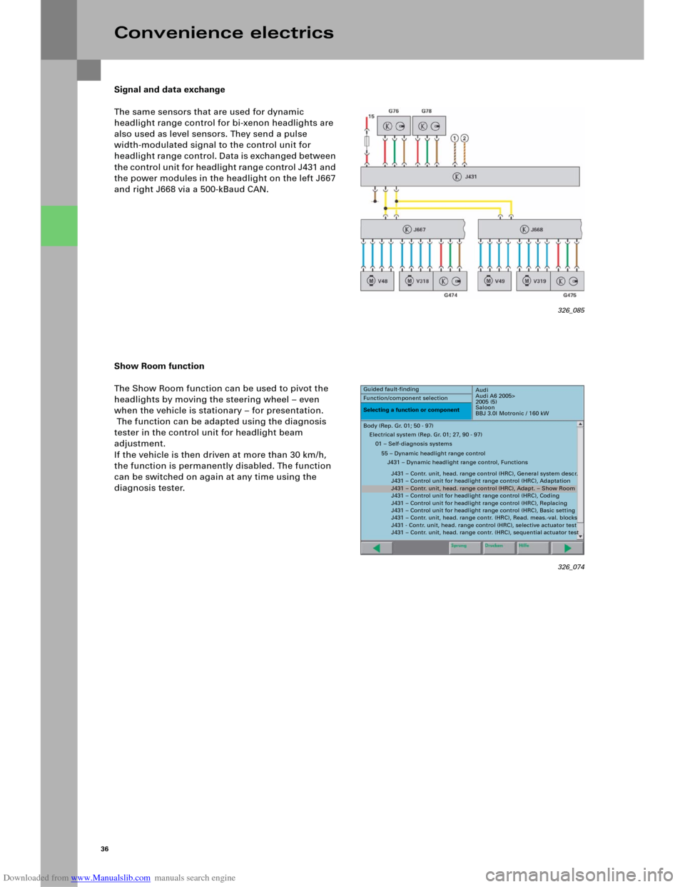
Signal and data exchange
The same sensors that are used for dynamic
headlight range control for bi-xenon headlights are
also used as level sensors. They send a pulse
width-modulated signal to the control unit for
headlight range control. Data is exchanged between
t h e c o n t ro l u n i t fo r h e ad l i gh t ra n g e c o n tro l J 4 3 1 an d
the power modules in the headlight on the left J667
and right J668 via a 500-kBaud CAN.
Show Room function
The Show Room function can be used to pivot the
headlights by moving the steering wheel – even
when the vehicle is stationary – for presentation.
The function can be adapted using the diagnosis
tester in the control unit for headlight beam
adjustment.
If the vehicle is then driven at more than 30 km/h,
the function is permanently disabled. The function
can be switched on again at any time using the
diagnosis tester.
Convenience electrics
326_074
Audi
Audi A6 2005>
2005 (5)
Saloon
BBJ 3.0l Motronic / 160 kW Guided fault-finding
Function/component selection
Selecting a function or component
Body (Rep. Gr. 01; 50 - 97)
Electrical system (Rep. Gr. 01; 27, 90 - 97)
01 – Self-diagnosis systems
55 – Dynamic headlight range control
J431 – Dynamic headlight range control, Functions
J431 – Contr. unit, head. range control (HRC), General system descr.
J431 – Control unit for headlight range control (HRC), Adaptation
J431 – Contr. unit, head. range control (HRC), Adapt. – Show Room
J431 – Control unit for headlight range control (HRC), Coding
J431 – Control unit for headlight range control (HRC), Replacing
J431 – Control unit for headlight range control (HRC), Basic setting
J431 – Contr. unit, head. range contr. (HRC), Read. meas.-val. blocks
J431 - Contr. unit, head. range control (HRC), selective actuator test
J431 – Contr. unit, head. range contr. (HRC), sequential actuator test
326_085
Page 41 of 92
Downloaded from www.Manualslib.com manuals search engine 43
Emergency function
The software for the control unit for on-board power
supply can be used to implement emergency
functions. If a fault is detected in the rotary light
switch or if there is an open circuit in the line to the
rotary light switch, the control unit for on-board
power supply switches the driving light on.
Other functionalities
In addition to the master functions, the following
functions are also available in the control unit for
on-board power supply.
– Steering column adjustment
– Footwell lighting
– Selector gate lighting
– Direction indicator control, front and side
– Signal horn activation
– Windscreen washer pump activation
– Steering column memory
Versi on s
There are three functional versions of the control
unit for on-board power supply:
– Low-Line version (with no electric steering
column adjustment, no xenon, no daytime
driving lights)
– Mid-Line version (with no electric steering
column adjustment, with xenon and daytime
driving lights)
– High-Line version (with electric steering column
adjustment, xenon and daytime driving lights)
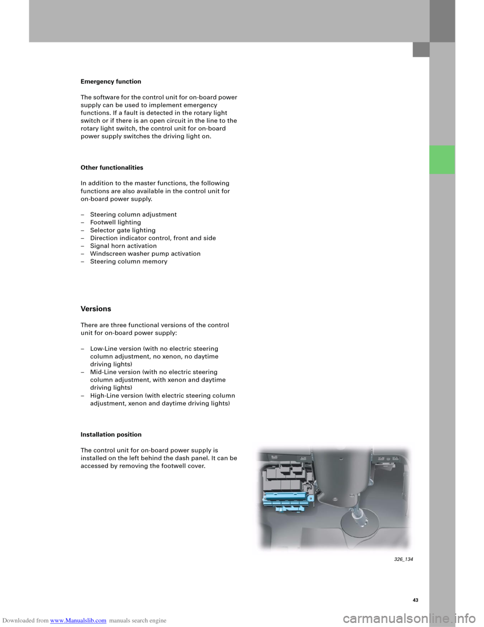
Installation position
The control unit for on-board power supply is
installed on the left behind the dash panel. It can be
accessed by removing the footwell cover.
326_134
Page 42 of 92
Downloaded from www.Manualslib.com manuals search engine 44
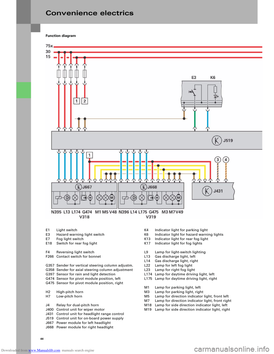
Function diagram
Convenience electrics
E1 Light switch
E3 Hazard warning light switch
E7 Fog light switch
E18 Switch for rear fog light
F4 Reversing light switch
F266 Contact switch for bonnet
G357 Sender for vertical steering column adjustm.
G358 Sender for axial steering column adjustment
G397 Sensor for rain and light detection
G474 Sensor for pivot module position, left
G475 Sensor for pivot module position, right
H2 High-pitch horn
H7 Low-pitch horn
J4 Relay for dual-pitch horn
J400 Control unit for wiper motor
J431 Control unit for headlight range control
J519 Control unit for on-board power supply
J667 Power module for left headlight
J668 Power module for right headlightK4 Indicator light for parking light
K6 Indicator light for hazard warning lights
K13 Indicator light for rear fog light
K17 Indicator light for fog lights
L9 Lamp for light-switch lighting
L13 Gas discharge light, left
L14 Gas discharge light, right
L22 Lamp for left fog light
L23 Lamp for right fog light
L174 Lamp for daytime driving light, left
L175 Lamp for daytime driving light, right
M1 Lamp for parking light, left
M3 Lamp for parking light, right
M5 Lamp for direction indicator light, front left
M7 Lamp for direction indicator light, front right
M18 Lamp for side direction indicator light, left
M19 Lamp for side direction indicator light, right
Page 44 of 92
Downloaded from www.Manualslib.com manuals search engine 46
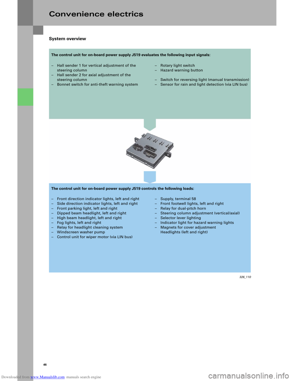
System overview
Convenience electrics
– Hall sender 1 for vertical adjustment of the
steering column
– Hall sender 2 for axial adjustment of the
steering column
– Bonnet switch for anti-theft warning system–Rotary light switch
–Hazard warning button
– Switch for reversing light (manual transmission)
– Sensor for rain and light detection (via LIN bus)
– Front direction indicator lights, left and right
– Side direction indicator lights, left and right
– Front parking light, left and right
– Dipped beam headlight, left and right
– High beam headlight, left and right
– Fog lights, left and right
– Relay for headlight cleaning system
– Windscreen washer pump
– Control unit for wiper motor (via LIN bus)– Supply, terminal 58
– Front footwell lights, left and right
– Relay for dual-pitch horn
– Steering column adjustment (vertical/axial)
– Selector lever lighting
– Indicator light for hazard warning lights
– Magnets for cover adjustment
Headlights (left and right)
326_110
The control unit for on-board power supply J519 evaluates the following input signals:
The control unit for on-board power supply J519 controls the following loads:
Page 45 of 92
Downloaded from www.Manualslib.com manuals search engine 47
Diagnosis
Basic settings
After the control unit for on-board power
supply J519 or the steering column or the switch for
steering column adjustment E167 is replaced, a
basic setting in axial and vertical position must be
implemented for the steering column.
Actuator test
An actuator test can be used to carry out the
following checks:
– Indicator light for hazard warning lights K6
– Lamp for parking light, left M1
– Lamp for parking light, right M3
– Lamp for dipped beam headlight, left M29
– Lamp for dipped beam headlight, right M31
– Lamp for high beam headlight, left M30
– Lamp for high beam headlight, right M32
– Lamp for left fog light L22
– Lamp for right fog light L23
– Lamp for daytime driving light, left L174
– Lamp for daytime driving light, right L175
– Direction indicator lights, left
– Direction indicator lights, right
– Footwell light, left W9
– Footwell light, right W10
– Wiper, top turning position
– Wiper, bottom turning position
– Windscreen washer pump V5
– Relay for dual-pitch horn
–Terminal 58
Coding
The control unit for on-board power supply J519 can
be coded for the functions
–Daytime driving light,
– Driving light assistant,
– Headlight type,
– Footwell lighting and
–Country versions
using the diagnosis tester.
Note
The actuator test can be performed either
sequentially (in sequence) or selectively
(individual selection).