2005 AUDI A6 brake sensor
[x] Cancel search: brake sensorPage 5 of 92
Downloaded from www.Manualslib.com manuals search engine 5
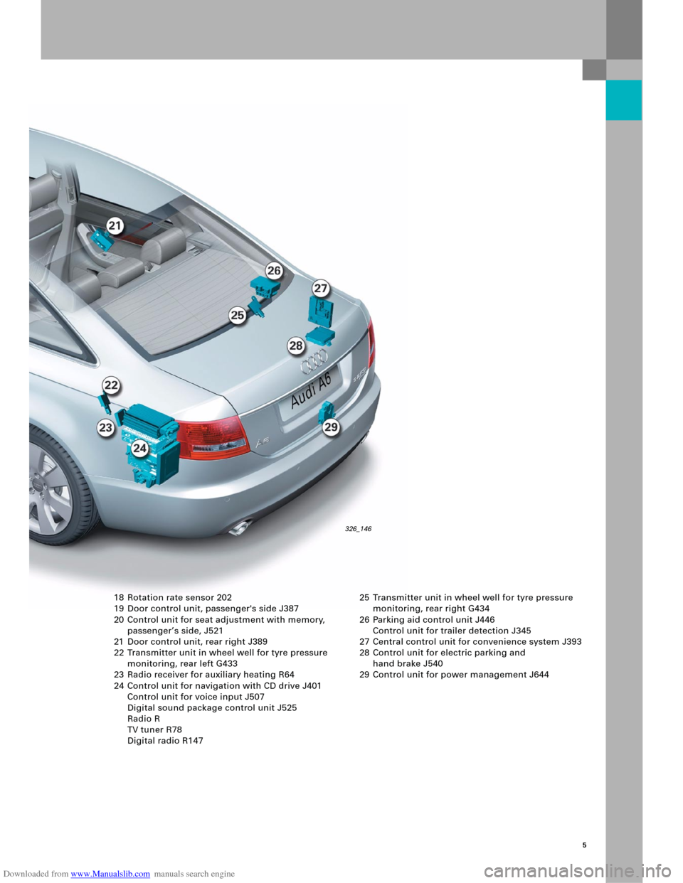
18 Rotation rate sensor 202
19 Door control unit, passenger's side J387
20 Control unit for seat adjustment with memory,
passenger’s side, J521
21 Door control unit, rear right J389
22 Transmitter unit in wheel well for tyre pressure
monitoring, rear left G433
23 Radio receiver for auxiliary heating R64
24 Control unit for navigation with CD drive J401
Control unit for voice input J507
Digital sound package control unit J525
Radio R
TV tuner R78
Digital radio R147 25 Transmitter unit in wheel well for tyre pressure
monitoring, rear right G434
26 Parking aid control unit J446
Control unit for trailer detection J345
27 Central control unit for convenience system J393
28 Control unit for electric parking and
hand brake J540
29 Control unit for power management J644
326_146
Page 6 of 92
Downloaded from www.Manualslib.com manuals search engine 6
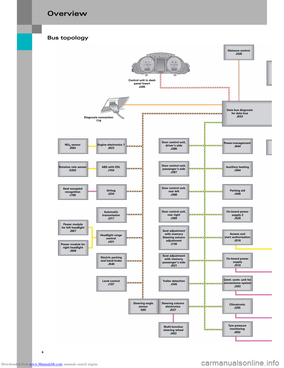
Bus topology
Overview
NOX sensor
J583
Rotation rate sensor
G202
Seat occupied
recognition
J706
Power module
for left headlight
J667
Power m odule for
right headlight
J668
Level control
J197 Electric parking
and hand brake
J540 Headlight range
control
J431 Automatic
transmission
J217 Airbag
J234 ABS with EDL
J104 Engine electronics 1
J623 Diagnosis connection
T16Control unit in dash
panel insert
J285Distance control
J428
Data bus diagnosis
for data bus
J533
Door control unit,
driver’s side
J386
Door control unit,
passenger’s side
J387
Door control unit,
rear left
J388
Door control unit,
rear right
J389
Seat adjustment
with memory
Steering column
adjustment
J136
Seat adjustment
with memory,
passenger’s side
J521
Trailer detection
J345
Steering column
electronics
J527
Multi-function
steering wheel
J453 Steering-angle
sensor
G85Power management
J644
Auxiliary heating
J364
Parking aid
J446
On-board power
supply 2
J520
Access and
start authorisation
J518
On-board power
supply
J519
Centr. contr. unit for
convenience system
J393
Climatronic
J255
Tyre pressure
monitoring
J502
Page 12 of 92
Downloaded from www.Manualslib.com manuals search engine Convenience electricsFunction diagramLegend
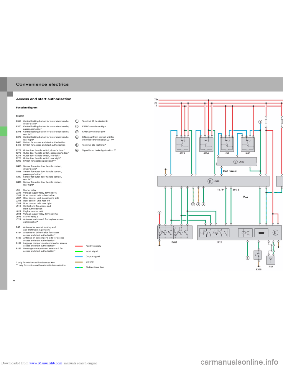
E369 Central locking button for outer door handle,
driver’s side*
E370 Central locking button for outer door handle,
passenger’s side*
E371 Central locking button for outer door handle,
rear left*
E372 Central locking button for outer door handle,
rear right*
E408 Button for access and start authorisation
E415 Switch for access and start authorisation
F272 Outer door handle switch, driver’s door*
F273 Outer door handle switch, passenger’s door*
F274 Outer door handle switch, rear left*
F275 Outer door handle switch, rear right*
F305 Switch for gearbox position P**
G415 Sensor for outer door handle contact,
driver’s side*
G416 Sensor for outer door handle contact,
passenger’s side*
G417 Sensor for outer door handle contact,
rear left*
G418 Sensor for outer door handle contact,
rear right*
J53 Starter relay
J329 Voltage supply relay, terminal 15
J386 Door control unit, driver's side
J387 Door control unit, passenger's side
J388 Door control unit, rear left
J389 Door control unit, rear right
J518 Control unit for access and
start authorisation
J623 Engine control unit
J694 Voltage supply relay, terminal 75x
J695 Starter relay 2
J723 Antenna read-in unit for keyless access
authorisation*
R47 Antenna for central locking and
anti-theft warning system
R134 Antenna on driver’s side for access
access and start authorisation*
R135 Antenna on passenger’s side for access
access and start authorisation*
R137 Luggage compartment antenna for access
access and start authorisation*
R138 Passenger compartment antenna 1 for
access and start authorisation*
* only for vehicles with Advanced Key
** only for vehicles with automatic transmission
1 Terminal 50 (to starter B)
2 CAN Convenience High
3 CAN Convenience Low
4 P/N signal from control unit for
automatic transmission J217**
5 Terminal 58s (lighting)*
6 Signal from brake light switch F*
Positive supply
Input signal
Output signal
Ground
Bi-directional line
13
Access and start authorisation
Start request
Ulock
Page 33 of 92
Downloaded from www.Manualslib.com manuals search engine 35
Internal structure
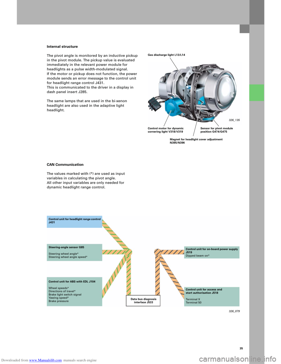
The pivot angle is monitored by an inductive pickup
in the pivot module. The pickup value is evaluated
immediately in the relevant power module for
headlights as a pulse width-modulated signal.
If the motor or pickup does not function, the power
module sends an error message to the control unit
for headlight range control J431.
This is communicated to the driver in a display in
dash panel insert J285.
The same lamps that are used in the bi-xenon
headlight are also used in the adaptive light
headlight.
CAN Communication
The values marked with (*) are used as input
variables in calculating the pivot angle.
All other input variables are only needed for
dynamic headlight range control.
326_079 Data bus diagnosis
interface J533 Co n t ro l u n it fo r h e a d li g h t ra n g e c o n t ro l
J431
Steering-angle sensor G85
Steering wheel angle*
Steering wheel angle speed*
Control unit for ABS with EDL J104
Wheel speeds*
Directions of travel*
Brake light switch signal
Yawing speed*
Brake pressureControl unit for on-board power supply
J519
Dipped beam on*
Control unit for access and
start authorisation J518
Te r m i n a l X
Te r m i n a l 5 0
Gas discharge light L13/L14
326_135
Control motor for dynamic
cornering light V318/V319
Magnet for headlight cover adjustment
N395/N396Sensor for pivot module
position G474/G475
Page 39 of 92
Downloaded from www.Manualslib.com manuals search engine 41
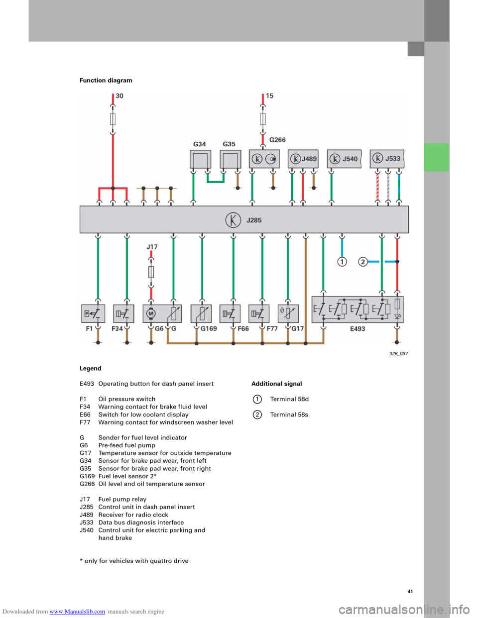
Function diagram
Legend
E493 Operating button for dash panel insert
F1 Oil pressure switch
F34 Warning contact for brake fluid level
E66 Switch for low coolant display
F77 Warning contact for windscreen washer level
G Sender for fuel level indicator
G6 Pre-feed fuel pump
G17 Temperature sensor for outside temperature
G34 Sensor for brake pad wear, front left
G35 Sensor for brake pad wear, front right
G169 Fuel level sensor 2*
G266 Oil level and oil temperature sensor
J17 Fuel pump relay
J285 Control unit in dash panel insert
J489 Receiver for radio clock
J533 Data bus diagnosis interface
J540 Control unit for electric parking and
hand brake
* only for vehicles with quattro drive
326_037
Additional signal
1 Terminal 58d
2 Terminal 58s
Page 54 of 92
Downloaded from www.Manualslib.com manuals search engine 56
326_121
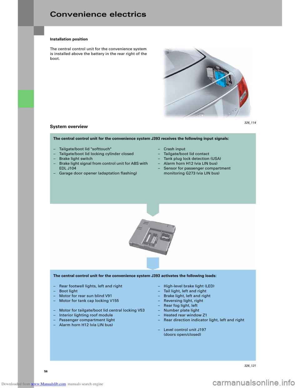
Installation position
The central control unit for the convenience system
is installed above the battery in the rear right of the
boot.
System overview
Convenience electrics
– Tailgate/boot lid "softtouch"
– Tailgate/boot lid locking cylinder closed
– Brake light switch
– B rake li ght signal from control u ni t fo r ABS with
EDL J104
– Garage door opener (adaptation flashing)– Crash input
– Tailgate/boot lid contact
–Tank plug lock detection (USA)
– Alarm horn H12 (via LIN bus)
– Sensor for passenger compartment
monitoring G273 (via LIN bus)
– Rear footwell lights, left and right
– Boot light
– Motor for rear sun blind V91
– Motor for tank cap locking V155
– Motor for tailgate/boot lid central locking V53
– Interior lighting roof module
– Passenger compartment light
– Alarm horn H12 (via LIN bus)– High-level brake light (LED)
– Tail light, left and right
–Brake light, left and right
– Reversing light, right
–Rear fog light, left
– Number plate light
– Heated rear window Z1
– Rear direction indicator light, left and right
– Level control unit J197
(doors open/closed) The central control unit for the convenience system J393 receives the following input signals:
The central control unit for the convenience system J393 activates the following loads:
326_114
Page 56 of 92
Downloaded from www.Manualslib.com manuals search engine 58
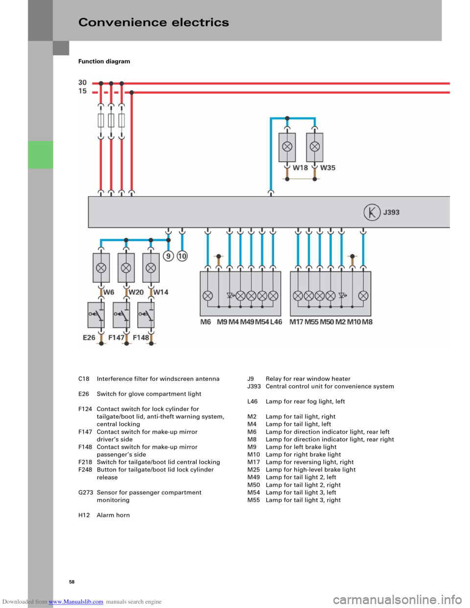
Function diagram
Convenience electrics
C18 Interference filter for windscreen antenna
E26 Switch for glove compartment light
F124 Contact switch for lock cylinder for
tailgate/boot lid, anti-theft warning system,
central locking
F147 Contact switch for make-up mirror
driver’s side
F148 Contact switch for make-up mirror
passenger’s side
F218 Switch for tailgate/boot lid central locking
F248 Button for tailgate/boot lid lock cylinder
release
G273 Sensor for passenger compartment
monitoring
H12 Alarm hornJ9 Relay for rear window heater
J393 Central control unit for convenience system
L46 Lamp for rear fog light, left
M2 Lamp for tail light, right
M4 Lamp for tail light, left
M6 Lamp for direction indicator light, rear left
M8 Lamp for direction indicator light, rear right
M9 Lamp for left brake light
M10 Lamp for right brake light
M17 Lamp for reversing light, right
M25 Lamp for high-level brake light
M49 Lamp for tail light 2, left
M50 Lamp for tail light 2, right
M54 Lamp for tail light 3, left
M55 Lamp for tail light 3, right
Page 58 of 92
Downloaded from www.Manualslib.com manuals search engine 60
Diagnosis
The central control unit for convenience
system, J393, has the usual diagnostic functions,
such as read fault memory, read measured value
blocks, adaptation, coding, as well as selective and
sequential actuator test at its disposal.
Actuator test
The selective actuator test initiated by the diagnosis
tester can be used to check the following actuators:
– Indicator light for safe central locking K133
(in door rim)
– Lock central locking signal (once)
– Activate safe locking for doors (once)
– Unlock central locking signal
– Lock filler flap
– Unlock filler flap
– Lamp for left brake light M9
– Lamp for right brake light M10
– Lamp for high-level brake light M25
– Lamps for tail light, left
– Lamp for parking light, left M43
– Lamps for tail light, right
– Lamp for parking light, right M44
– Lamp for reversing light, left M16
– Lamp for reversing light, right M17
– Lamp for direction indicator light, rear left M6
– Lamp for direction indicator light, rear right M8
– Lamp for rear fog light, left L46
– Lamp for rear fog light, right L47
Coding
This diagnostic option can be used to perform
coding, for example, for these functions:
– Anti-theft warning system
– Central locking (normal/selective)
–Tilt sensor
– Passenger compartment sensor
– Convenience function via radio
–Right-hand traffic
–Avant detection
–Rear sun blind
Convenience electrics
Note
In addition to the selective actuator test,
the diagnosis software also includes the option
of a sequential actuator test.
– Number plate light X
– Boot light W3
– Footwell light, rear left W45
– Footwell light, rear right W46
– Activation of rear lid remote unlocking
(rotary latch opens, closing aid moves up)
– Motor for rear sun blind (rear sun blind moves in
both directions)
– Signal for rear window heater activation
–Interior lighting
– Acknowledgement of anti-theft warning system
horn
–RoW/USA
–Light package
– Tank cap lock detection
– Equipment (Basic/High-Line)
–Sliding roof
– Multi-function control unit (taxi/emergency
doctor/fire brigade, installed/not installed)