2005 AUDI A6 bluetooth
[x] Cancel search: bluetoothPage 2 of 92
Downloaded from www.Manualslib.com manuals search engine The new Audi A6 – the most progressive vehicle
takes the lead.
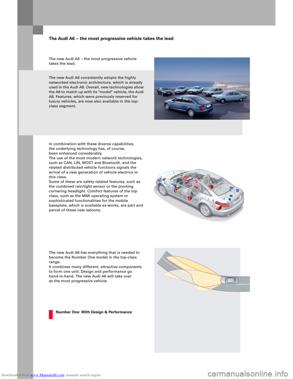
The new Audi A6 consistently adopts the highly
networked electronic architecture, which is already
used in the Audi A8. Overall, new technologies allow
the A6 to match up with its "model" vehicle, the Audi
A8. Features, which were previously reserved for
luxury vehicles, are now also available in the top-
class segment.
In combination with these diverse capabilities,
the underlying technology has, of course,
been enhanced considerably.
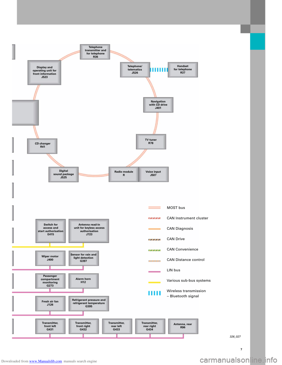
The use of the most modern network technologies,
such as CAN, LIN, MOST and Bluetooth, and the
related distributed vehicle functions signals the
arrival of a new generation of vehicle electrics in
this class.
Some of these are safety-related features, such as
the combined rain/light sensor or the pivoting
cornering headlight. Comfort features of the top
class, such as the MMI operating system or
sophisticated functionalities for the mobile
baseplate, which is available ex-works, are part and
parcel of these new saloons.
The new Audi A6 has everything that is needed to
become the Number One model in the top-class
range.
It combines many different, attractive components
to form one unit. Design and performance go
hand-in-hand. The new Audi A6 will take over
as the most progressive vehicle.
The Audi A6 – the most progressive vehicle takes the lead
Number One: With Design & Performance
Page 7 of 92
Downloaded from www.Manualslib.com manuals search engine 7
326_027
Display and
operating unit for
front information
J523Te l e p h o n e
transmitter and
for telephone
R36
CD changer
R41
Digital
sound package
J525
Switch for
access and
start authorisation
E415Antenna read-in
unit for keyless access
authorisation
J723
Wiper motor
J400Sensor for rain and
light detection
G397
Passenger
compartment
monitoring
G273Alarm horn
H12
Fresh air fan
J126Refrigerant pressure and
refrigerant temperature
G395
Tr a n s m i t t e r,
front left
G431Tr a n s m i t t e r,
front right
G432Tr a n s m i t t e r,
rear left
G433Transmitter,
rear right
G434Antenna, rear
R96 Te l e p h o n e /
telematics
J526Handset
for telephone
R37
Navigation
with CD drive
J401
TV tuner
R78
Radio module
RVoice input
J507
MOST bus
CAN Instrument cluster
CAN Diagnosis
CAN Drive
CAN Convenience
CAN Distance control
LIN bus
Various sub-bus systems
Wireless transmission
– Bluetooth signal
Page 66 of 92
Downloaded from www.Manualslib.com manuals search engine 68
Multimedia Interface (MMI)
Equipment versions
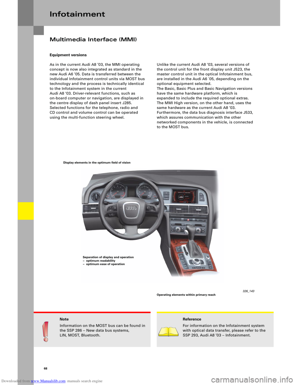
As in the current Audi A8 ’03, the MMI operating
concept is now also integrated as standard in the
new Audi A6 ’05. Data is transferred between the
individual Infotainment control units via MOST bus
technology and the process is technically identical
to the Infotainment system in the current
Audi A8 ‘03. Driver-relevant functions, such as
on-board computer or navigation, are displayed in
the centre display of dash panel insert J285.
Selected functions for the telephone, radio and
CD control and volume control can be operated
using the multi-function steering wheel.Unlike the current Audi A8 ‘03, several versions of
the control unit for the front display unit J523, the
master control unit in the optical Infotainment bus,
are installed in the Audi A6 ´05, depending on the
optional equipment selected.
The Basic, Basic Plus and Basic Navigation versions
have the same hardware platform, which is
expanded to include the required optional extras.
The MMI High version, on the other hand, uses the
same hardware as the current Audi A8 ‘03.
Furthermore, the data bus diagnosis interface J533,
which assures communication with the other
networked components in the vehicle, is connected
to the MOST bus.
Infotainment
Note
Information on the MOST bus can be found in
the SSP 286 – New data bus systems,
LIN, MOST, Bluetooth.Reference
For information on the Infotainment system
with optical data transfer, please refer to the
SSP 293, Audi A8 ’03 – Infotainment.
326_143 Display elements in the optimum field of vision
Separation of display and operation
– optimum readability
– optimum ease of operation
Operating elements within primary reach
Page 84 of 92
Downloaded from www.Manualslib.com manuals search engine 86
Available telephone systems
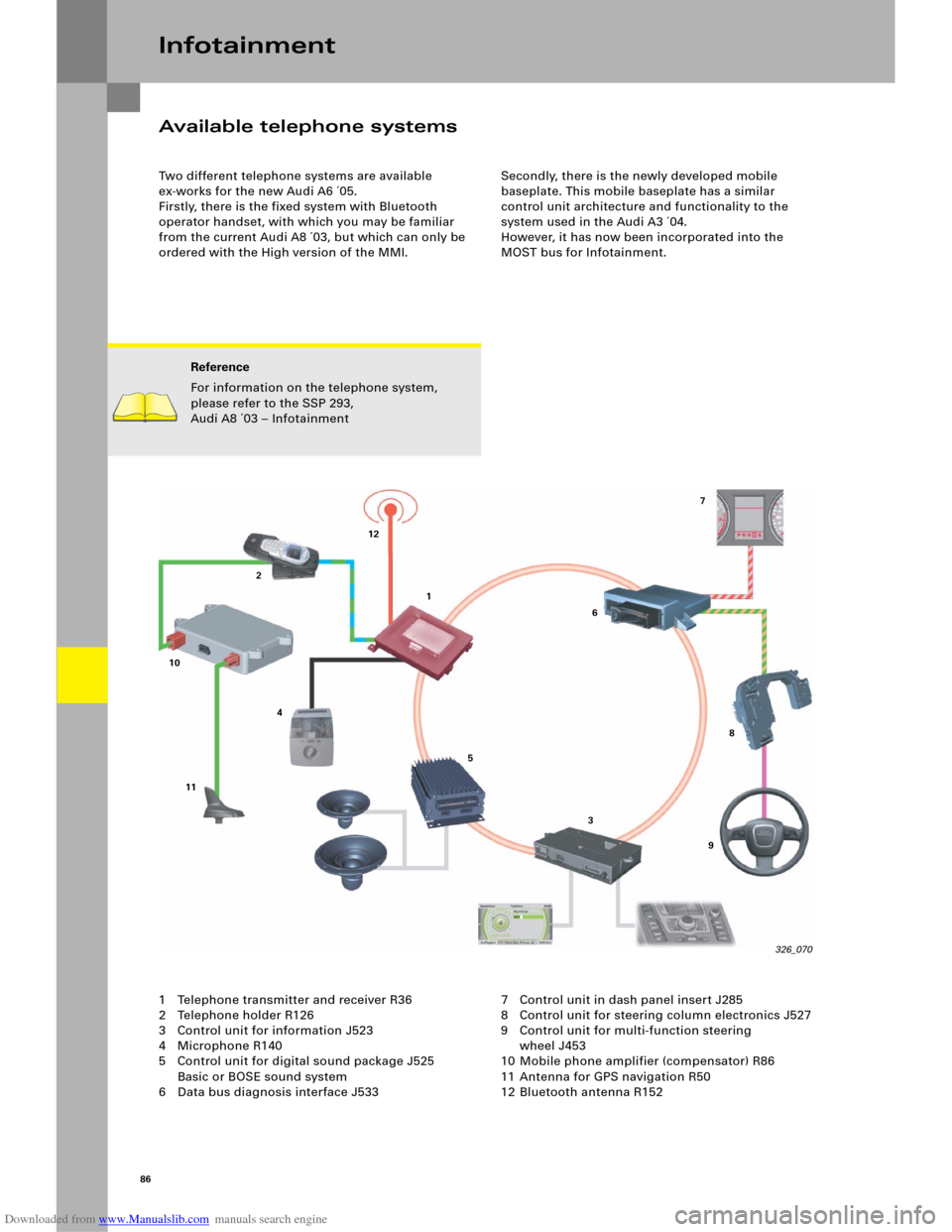
Two different telephone systems are available
ex-works for the new Audi A6 ´05.
Firstly, there is the fixed system with Bluetooth
operator handset, with which you may be familiar
from the current Audi A8 ´03, but which can only be
ordered with the High version of the MMI. Secondly, there is the newly developed mobile
baseplate. This mobile baseplate has a similar
control unit architecture and functionality to the
system used in the Audi A3 ´04.
However, it has now been incorporated into the
MOST bus for Infotainment.
Infotainment
1 Telephone transmitter and receiver R36
2 Telephone holder R126
3 Control unit for information J523
4 Microphone R140
5 Control unit for digital sound package J525
Basic or BOSE sound system
6 Data bus diagnosis interface J533 7 Control unit in dash panel insert J285
8 Control unit for steering column electronics J527
9 Control unit for multi-function steering
wheel J453
10 Mobile phone amplifier (compensator) R86
11 Antenna for GPS navigation R50
12 Bluetooth antenna R152
Reference
For information on the telephone system,
please refer to the SSP 293,
Audi A8 ´03 – Infotainment
326_070 11 10212
41
5
367
8
9
Page 85 of 92
Downloaded from www.Manualslib.com manuals search engine 87
The telephone transmitter and receiver R36 is fitted
as standard with a Bluetooth module.
In principle, the Bluetooth functionality
is always available, even if a mobile phone holder is
not connected. For reasons of electromagnetic
compatibility, Bluetooth is only active at present
when the mobile phone is inserted into the relevant
holder. The phonebook stored on the mobile phone
SIM card is read into the memory of the Telephone
transmitter and receiver R36 whenever the mobile
phone is inserted. Mobile-internal phonebooks
cannot be read in because the data formats differ
from model to model. The mobile baseplate is operated via the MMI in the
"TEL" menu. The telephone holder R126, which is
required for whichever type of mobile phone is to be
used, is available from the Parts Service. As you may
already know from the introduction of the new
mobile baseplate in other model series (Audi A3, A4,
TT), this mobile phone holder no longer has a
connection cable. It is connected to the telephone
transmitter and receiver R36 via a contact panel.
Voice operation
The new mobile baseplate can be voice-operated
using the operating unit in the steering wheel E221.
The handsfree volume can also be set using the
multi-function steering wheel and names or
telephone numbers can be dialled in the
phonebook. The operating unit in the steering
wheel E22 1 passes the data si gnals fo r this on to the
steering column electrics J527 as LIN signals.
This control unit converts the data into CAN
messages and transfers these messages to the data
bus diagnosis interface J533 on CAN Convenience.
Here, the digital data messages are converted into
MOST data records and are passed to the telephone
transmitter and receiver R36 via the MOST ring.
The adapter set always includes a Push-to-talk
button (PTT), which enables voice operation even
without the multi-function steering wheel option.
This button is included on every available mobile
phone adapter.
The PTT button has different functionalities,
depending on the MMI used:
– MMI High: Accept/Hang up
– MMI Basic/Basic Plus/Basic Navigation:
Accept/Hand up and also
Activate internal voice operation of the
telephone transmitter and receiver R36.
This internal voice operation function is only
available in the MMI Basic versions. Voice operation
in the MMI High version is implemented via the
optional control unit for voice input J507.
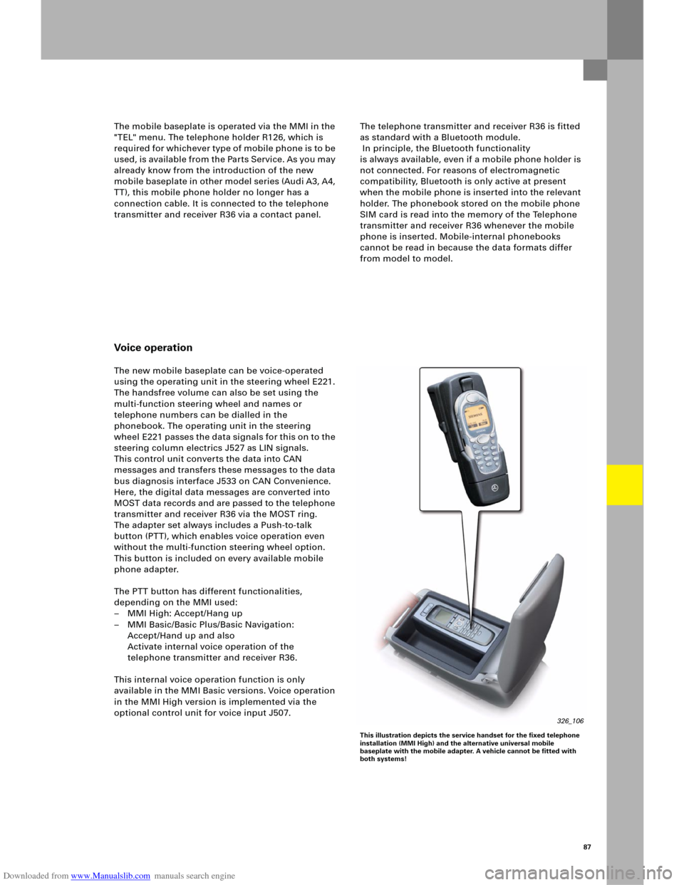
326_106
This illustration depicts the service handset for the fixed telephone
installation (MMI High) and the alternative universal mobile
baseplate with the mobile adapter. A vehicle cannot be fitted with
both systems!
Page 87 of 92
Downloaded from www.Manualslib.com manuals search engine 89
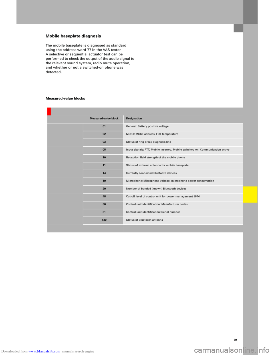
Mobile baseplate diagnosis
The mobile baseplate is diagnosed as standard
using the address word 77 in the VAS tester.
A selective or sequential actuator test can be
performed to check the output of the audio signal to
the relevant sound system, radio mute operation,
and whether or not a switched-on phone was
detected.
Measured-value blocks
Measured-value blockDesignation
01General: Battery positive voltage
02MOST: MOST address, FOT temperature
03Status of ring break diagnosis line
05Input signals: PTT, Mobile inserted, Mobile switched on, Communication active
10Reception field strength of the mobile phone
11Status of external antenna for mobile baseplate
14Currently connected Bluetooth devices
19Microphone: Microphone voltage, microphone power consumption
20Number of bonded (known) Bluetooth devices
48Cut-off level of control unit for power management J644
80Control unit identification: Manufacturer codes
81Control unit identification: Serial number
130Status of Bluetooth antenna
Page 88 of 92
Downloaded from www.Manualslib.com manuals search engine 90
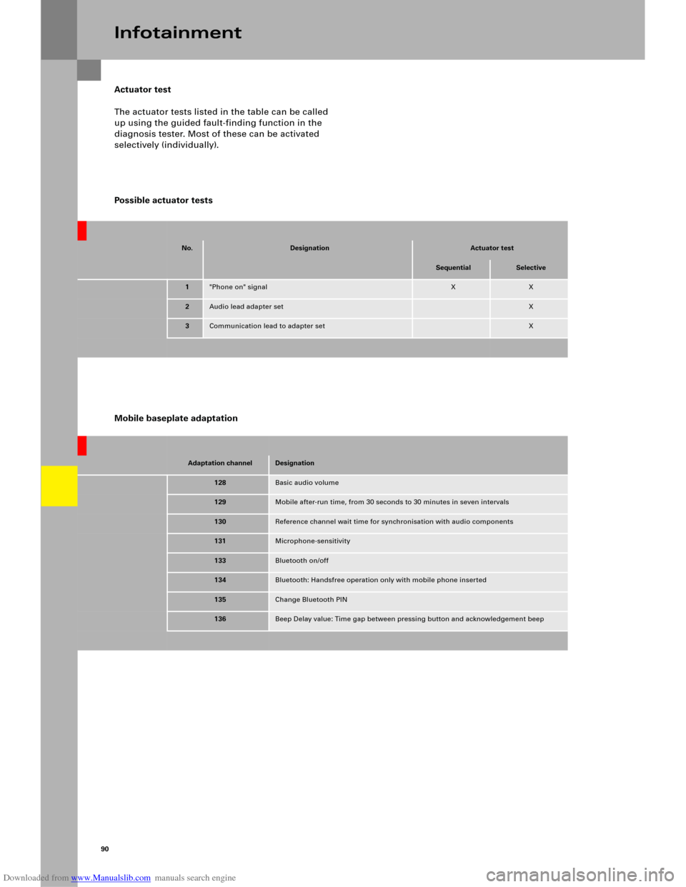
Actuator test
The actuator tests listed in the table can be called
up using the guided fault-finding function in the
diagnosis tester. Most of these can be activated
selectively (individually).
Possible actuator tests
Infotainment
Adaptation channelDesignation
128Basic audio volume
129Mobile after-run time, from 30 seconds to 30 minutes in seven intervals
130Reference channel wait time for synchronisation with audio components
131Microphone-sensitivity
133Bluetooth on/off
134Bluetooth: Handsfree operation only with mobile phone inserted
135Change Bluetooth PIN
136Beep Delay value: Time gap between pressing button and acknowledgement beep
Mobile baseplate adaptation
No.DesignationActuator test
SequentialSelective
1"Phone on" signalXX
2Audio lead adapter setX
3Communication lead to adapter setX