2005 AUDI A6 phone
[x] Cancel search: phonePage 3 of 92
Downloaded from www.Manualslib.com manuals search engine Note ReferenceNote Reference
Control unit installation positions . . . . . . . . . . . . . . . . . . . . . . . . . . . . . . . . . . . . . . . 4
Bus topology . . . . . . . . . . . . . . . . . . . . . . . . . . . . . . . . . . . . . . . . . . . . . . . . . . . . . . . . . . 6
Installation positions of fuses and relays . . . . . . . . . . . . . . . . . . . . . . . . . . . . . . . . . 8
Overview
Convenience electrics
Control unit for power management J644 . . . . . . . . . . . . . . . . . . . . . . . . . . . . . . . 10
Access and start authorisation . . . . . . . . . . . . . . . . . . . . . . . . . . . . . . . . . . . . . . . . . 13
Immobiliser and component protection . . . . . . . . . . . . . . . . . . . . . . . . . . . . . . . . . 30
External lights . . . . . . . . . . . . . . . . . . . . . . . . . . . . . . . . . . . . . . . . . . . . . . . . . . . . . . . . 32
Control unit in dash panel insert J285 . . . . . . . . . . . . . . . . . . . . . . . . . . . . . . . . . . 40
Control unit for on-board power supply J519 . . . . . . . . . . . . . . . . . . . . . . . . . . . . 42
Control unit 2 for on-board power supply J520 . . . . . . . . . . . . . . . . . . . . . . . . . . 52
Central control unit for convenience system J393 . . . . . . . . . . . . . . . . . . . . . . . . 55
Door control units J386 - J389 . . . . . . . . . . . . . . . . . . . . . . . . . . . . . . . . . . . . . . . . . 63
Control units for seat adjustment. . . . . . . . . . . . . . . . . . . . . . . . . . . . . . . . . . . . . . . 65
Infotainment
Multimedia interface . . . . . . . . . . . . . . . . . . . . . . . . . . . . . . . . . . . . . . . . . . . . . . . . . . 68
Antenna systems . . . . . . . . . . . . . . . . . . . . . . . . . . . . . . . . . . . . . . . . . . . . . . . . . . . . . 75
Control unit for front information J523 . . . . . . . . . . . . . . . . . . . . . . . . . . . . . . . . . . 76
Sound systems . . . . . . . . . . . . . . . . . . . . . . . . . . . . . . . . . . . . . . . . . . . . . . . . . . . . . . . 81
Available telephone systems . . . . . . . . . . . . . . . . . . . . . . . . . . . . . . . . . . . . . . . . . . . 86
The Self-Study Programme provides information on the fundamentals of design and function of new vehicle
models, new vehicle components or new technologies.
The Self-Study Programme is not a Workshop Manual!
Specified values serve only to make the information easier to understand and relate to the software version
that was valid at the time the Self-Study Programme (SSP) was created.
For maintenance and repair work, please make sure to use the current technical documentation.
Contents
Page 4 of 92
Downloaded from www.Manualslib.com manuals search engine 4
Overview
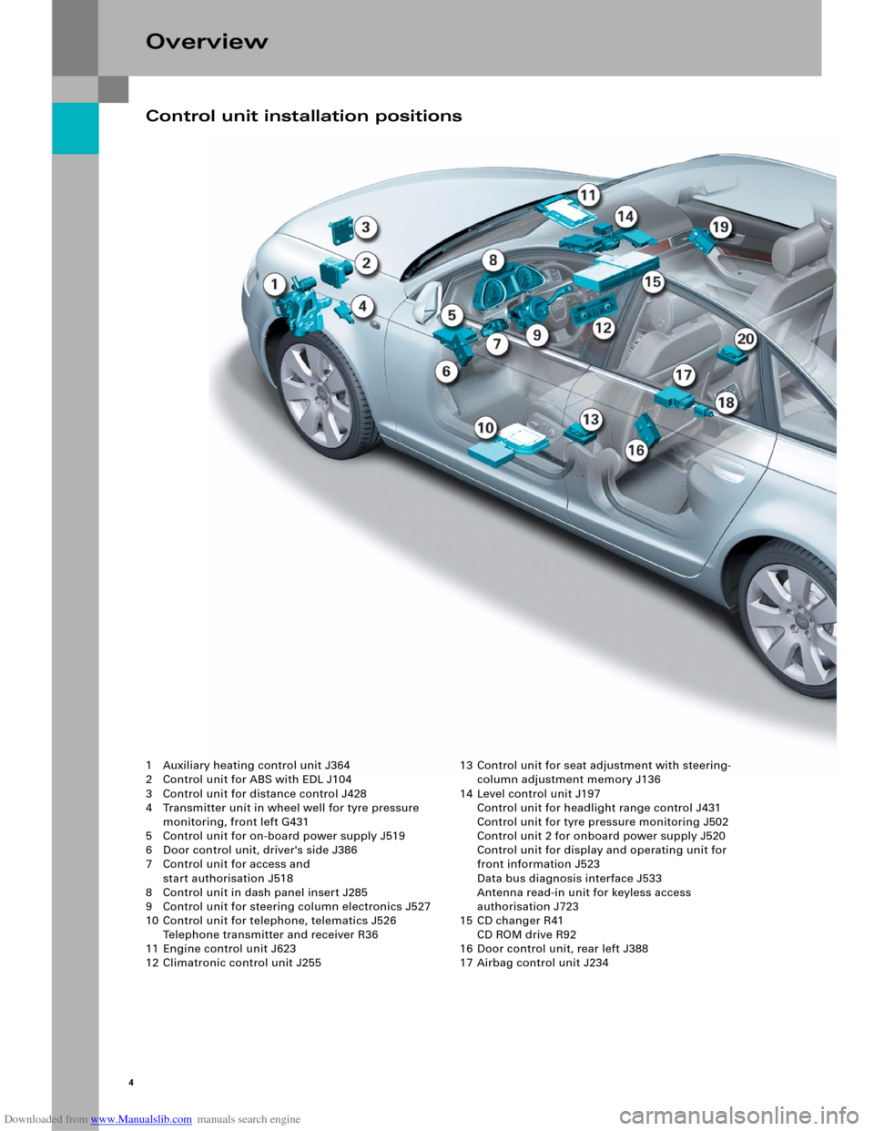
1 Auxiliary heating control unit J364
2 Control unit for ABS with EDL J104
3 Control unit for distance control J428
4 Transmitter unit in wheel well for tyre pressure
monitoring, front left G431
5 Control unit for on-board power supply J519
6 Door control unit, driver's side J386
7 Control unit for access and
start authorisation J518
8 Control unit in dash panel insert J285
9 Control unit for steering column electronics J527
10 Control unit for telephone, telematics J526
Telephone transmitter and receiver R36
11 Engine control unit J623
12 Climatronic control unit J25513 Control unit for seat adjustment with steering-
column adjustment memory J136
14 Level control unit J197
Control unit for headlight range control J431
Control unit for tyre pressure monitoring J502
Control unit 2 for onboard power supply J520
Control unit for display and operating unit for
front information J523
Data bus diagnosis interface J533
Antenna read-in unit for keyless access
authorisation J723
15 CD changer R41
CD ROM drive R92
16 Door control unit, rear left J388
17 Airbag control unit J234
Control unit installation positions
Page 7 of 92
Downloaded from www.Manualslib.com manuals search engine 7
326_027
Display and
operating unit for
front information
J523Te l e p h o n e
transmitter and
for telephone
R36
CD changer
R41
Digital
sound package
J525
Switch for
access and
start authorisation
E415Antenna read-in
unit for keyless access
authorisation
J723
Wiper motor
J400Sensor for rain and
light detection
G397
Passenger
compartment
monitoring
G273Alarm horn
H12
Fresh air fan
J126Refrigerant pressure and
refrigerant temperature
G395
Tr a n s m i t t e r,
front left
G431Tr a n s m i t t e r,
front right
G432Tr a n s m i t t e r,
rear left
G433Transmitter,
rear right
G434Antenna, rear
R96 Te l e p h o n e /
telematics
J526Handset
for telephone
R37
Navigation
with CD drive
J401
TV tuner
R78
Radio module
RVoice input
J507
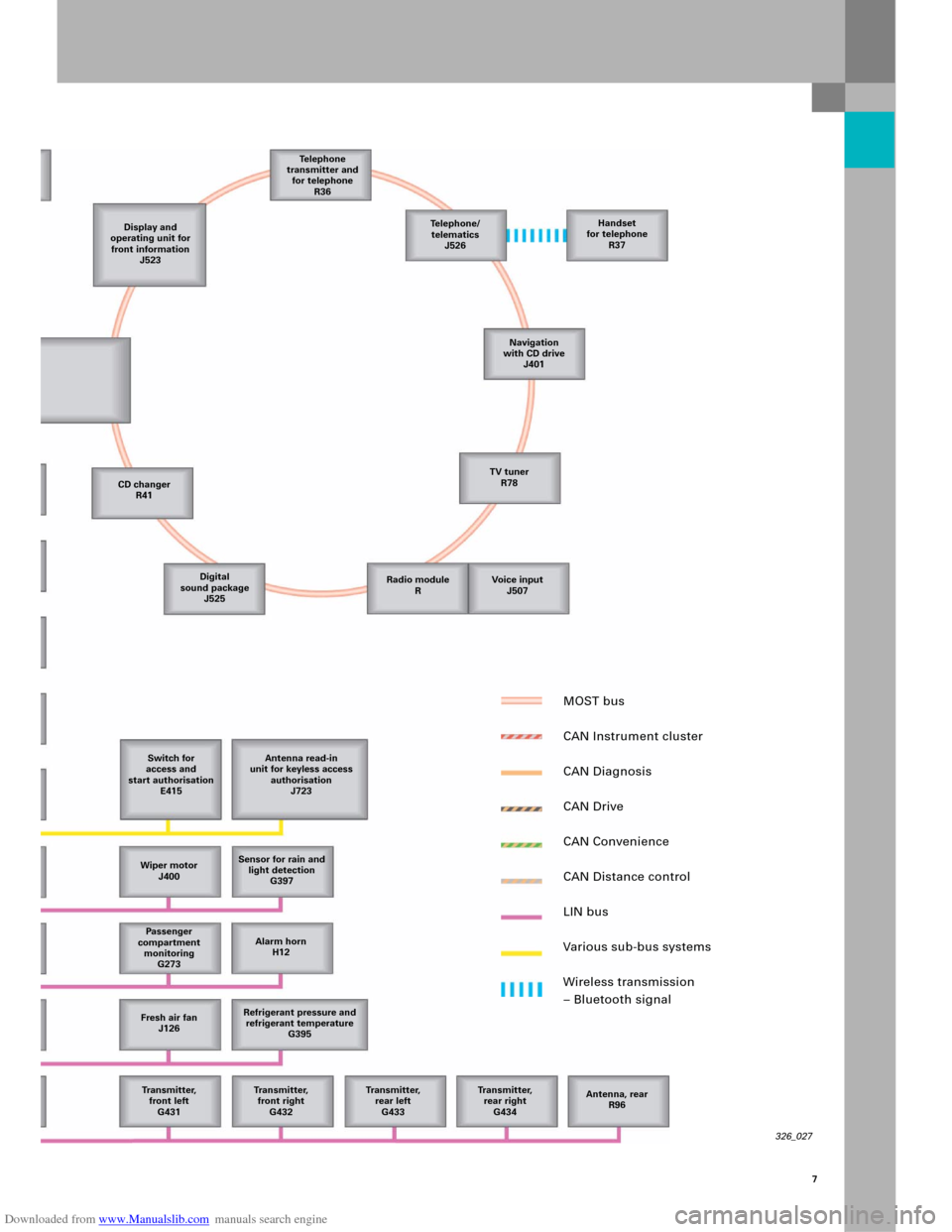
MOST bus
CAN Instrument cluster
CAN Diagnosis
CAN Drive
CAN Convenience
CAN Distance control
LIN bus
Various sub-bus systems
Wireless transmission
– Bluetooth signal
Page 21 of 92
Downloaded from www.Manualslib.com manuals search engine 23
Vehicl e ke y
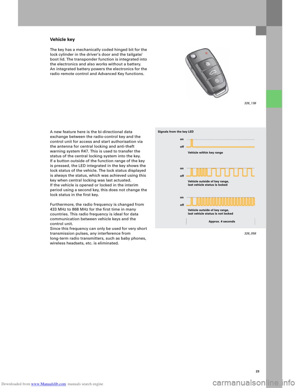
The key has a mechanically coded hinged bit for the
lock cylinder in the driver’s door and the tailgate/
boot lid. The transponder function is integrated into
the electronics and also works without a battery.
An integrated battery powers the electronics for the
radio remote control and Advanced Key functions.
A new feature here is the bi-directional data
exchange between the radio-control key and the
control unit for access and start authorisation via
the antenna for central locking and anti-theft
warning system R47. This is used to transfer the
status of the central locking system into the key.
If a button outside of the function range of the key
is pressed, the LED integrated in the key shows the
lock status of the vehicle. The lock status displayed
is always the status, which was achieved using this
key when central locking was last actuated.
If the vehicle is opened or locked in the interim
period using a second key, this does not change the
lock status in the first key.
Furthermore, the radio frequency is changed from
433 MHz to 868 MHz for the first time in many
countries. This radio frequency is ideal for data
communication between vehicle keys and the
control unit.
Since this frequency can only be used for very short
transmission pulses, any interference from
long-term radio transmitters, such as baby phones,
wireless headsets, etc. is eliminated.
326_138
326_058 Vehicle within key range
Vehicle outside of key range,
last vehicle status is locked Signals from the key LED
Vehicle outside of key range,
last vehicle status is not locked
Approx. 4 seconds on
off
on
off
on
off
Page 66 of 92
Downloaded from www.Manualslib.com manuals search engine 68
Multimedia Interface (MMI)
Equipment versions
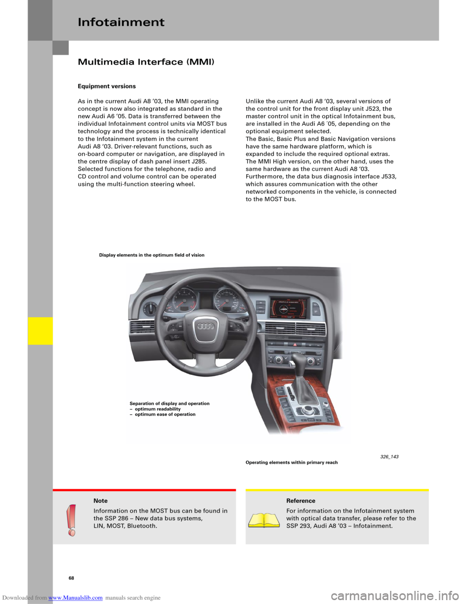
As in the current Audi A8 ’03, the MMI operating
concept is now also integrated as standard in the
new Audi A6 ’05. Data is transferred between the
individual Infotainment control units via MOST bus
technology and the process is technically identical
to the Infotainment system in the current
Audi A8 ‘03. Driver-relevant functions, such as
on-board computer or navigation, are displayed in
the centre display of dash panel insert J285.
Selected functions for the telephone, radio and
CD control and volume control can be operated
using the multi-function steering wheel.Unlike the current Audi A8 ‘03, several versions of
the control unit for the front display unit J523, the
master control unit in the optical Infotainment bus,
are installed in the Audi A6 ´05, depending on the
optional equipment selected.
The Basic, Basic Plus and Basic Navigation versions
have the same hardware platform, which is
expanded to include the required optional extras.
The MMI High version, on the other hand, uses the
same hardware as the current Audi A8 ‘03.
Furthermore, the data bus diagnosis interface J533,
which assures communication with the other
networked components in the vehicle, is connected
to the MOST bus.
Infotainment
Note
Information on the MOST bus can be found in
the SSP 286 – New data bus systems,
LIN, MOST, Bluetooth.Reference
For information on the Infotainment system
with optical data transfer, please refer to the
SSP 293, Audi A8 ’03 – Infotainment.
326_143 Display elements in the optimum field of vision
Separation of display and operation
– optimum readability
– optimum ease of operation
Operating elements within primary reach
Page 67 of 92
Downloaded from www.Manualslib.com manuals search engine 69
MMI Basic
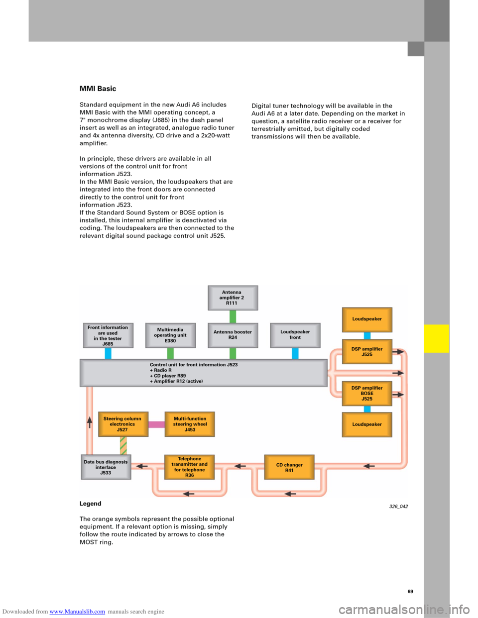
Standard equipment in the new Audi A6 includes
MMI Basic with the MMI operating concept, a
7" monochrome display (J685) in the dash panel
inser t as well as an integrated, analogue radio tuner
and 4x antenna diversity, CD drive and a 2x20-watt
amplifier.
In principle, these drivers are available in all
versions of the control unit for front
information J523.
In the MMI Basic version, the loudspeakers that are
integrated into the front doors are connected
directly to the control unit for front
information J523.
If the Standard Sound System or BOSE option is
installed, this internal amplifier is deactivated via
coding. The loudspeakers are then connected to the
relevant digital sound package control unit J525.Digital tuner technology will be available in the
Audi A6 at a later date. Depending on the market in
question, a satellite radio receiver or a receiver for
terrestrially emitted, but digitally coded
transmissions will then be available.
Legend
The orange symbols represent the possible optional
equipment. If a relevant option is missing, simply
follow the route indicated by arrows to close the
MOST ring.
326_042 Front information
are used
in the tester
J685Multimedia
operating unit
E380Antenna booster
R24Loudspeaker
front
Control unit for front information J523
+ Radio R
+ CD player R89
+ Amplifier R12 (active)Loudspeaker
DSP amplifier
J525
DSP amplifier
BOSE
J525
Loudspeaker
CD changer
R41 Te l e p h o n e
transmitter and
for telephone
R36 Data bus diagnosis
interface
J533Antenna
amplifier 2
R111
Steering column
electronics
J527Multi-function
steering wheel
J453
Page 68 of 92
Downloaded from www.Manualslib.com manuals search engine 70
MMI Basic Plus
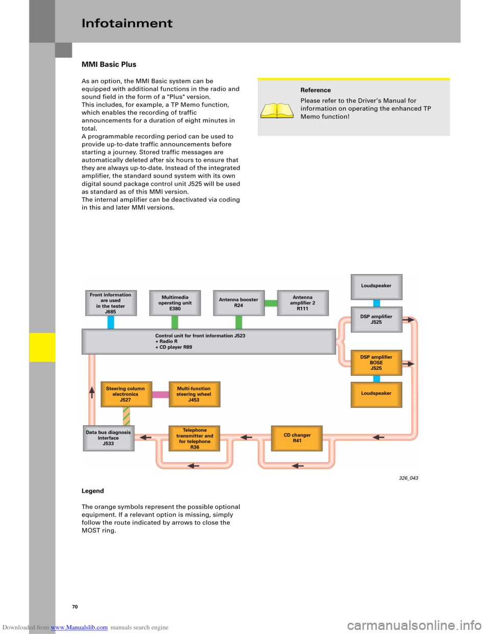
As an option, the MMI Basic system can be
equipped with additional functions in the radio and
sound field in the form of a "Plus" version.
This includes, for example, a TP Memo function,
which enables the recording of traffic
announcements for a duration of eight minutes in
total.
A programmable recording period can be used to
provide up-to-date traffic announcements before
starting a journey. Stored traffic messages are
automatically deleted after six hours to ensure that
they are always up-to -date. Instead of the integrated
amplifier, the standard sound system with its own
digital sound package control unit J525 will be used
as standard as of this MMI version.
The internal amplifier can be deactivated via coding
in this and later MMI versions.
Infotainment
Legend
The orange symbols represent the possible optional
equipment. If a relevant option is missing, simply
follow the route indicated by arrows to close the
MOST ring.
326_043 Front information
are used
in the tester
J685Multimedia
operating unit
E380Antenna booster
R24
Control unit for front information J523
+ Radio R
+ CD player R89Loudspeaker
DSP amplifier
J525
DSP amplifier
BOSE
J525
Loudspeaker
Te l e p h o n e
transmitter and
for telephone
R36 Data bus diagnosis
interface
J533CD changer
R41 Antenna
amplifier 2
R111
Reference
Please refer to the Driver’s Manual for
information on operating the enhanced TP
Memo function!
Steering column
electronics
J527Multi-function
steering wheel
J453
Page 69 of 92
Downloaded from www.Manualslib.com manuals search engine 71
MMI Basic Navigation
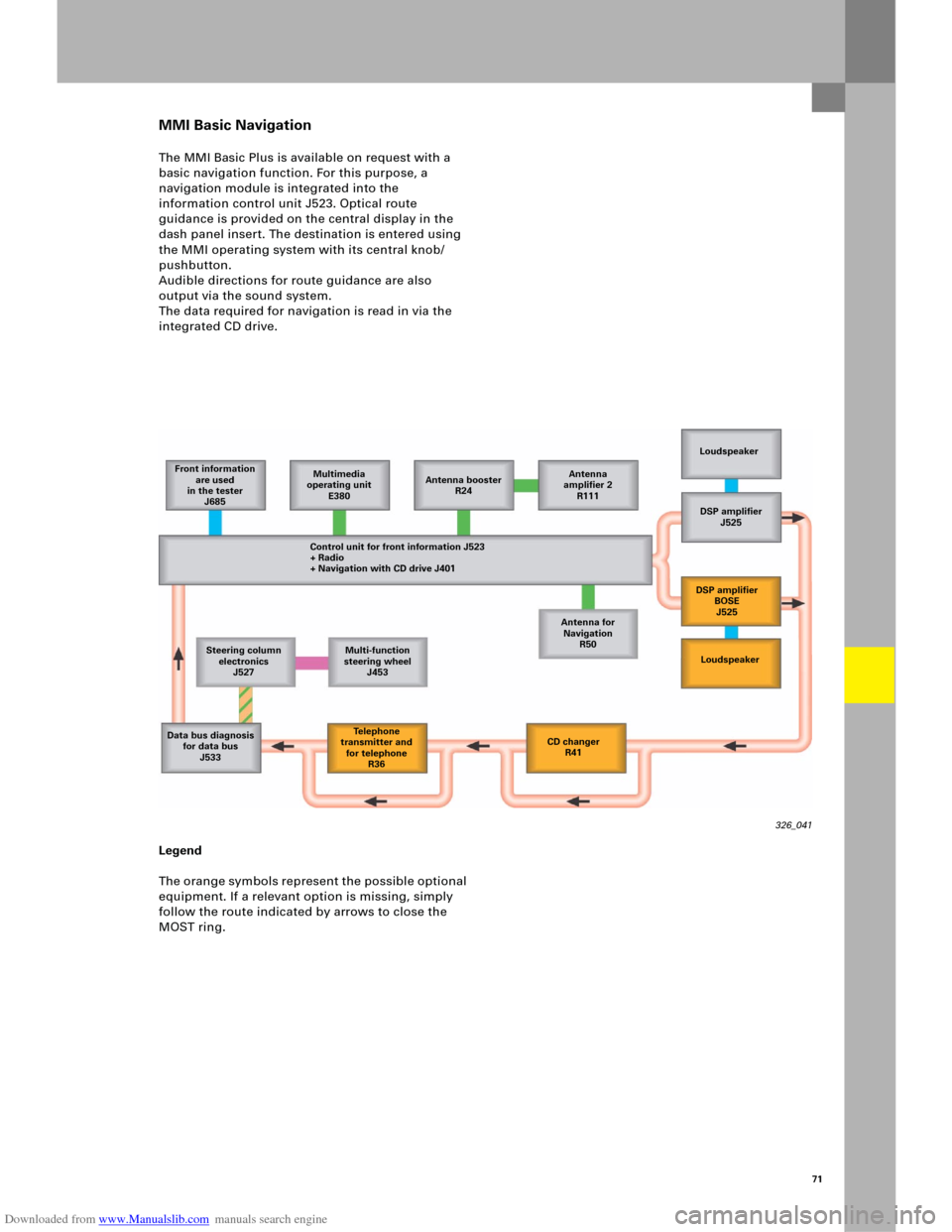
The MMI Basic Plus is available on request with a
basic navigation function. For this purpose, a
navigation module is integrated into the
information control unit J523. Optical route
guidance is provided on the central display in the
dash panel insert. The destination is entered using
the MMI operating system with its central knob/
pushbutton.
Audible directions for route guidance are also
output via the sound system.
The data required for navigation is read in via the
integrated CD drive.
Legend
The orange symbols represent the possible optional
equipment. If a relevant option is missing, simply
follow the route indicated by arrows to close the
MOST ring.
326_041
Front information
are used
in the tester
J685Multimedia
operating unit
E380Antenna booster
R24Antenna
amplifier 2
R111
Control unit for front information J523
+ Radio
+ Navigation with CD drive J401Loudspeaker
DSP amplifier
J525
Loudspeaker DSP amplifier
BOSE
J525
CD changer
R41 Te l e p h o n e
transmitter and
for telephone
R36 Data bus diagnosis
for data bus
J533Antenna for
Navigation
R50
Steering column
electronics
J527Multi-function
steering wheel
J453