2005 AUDI A6 relay
[x] Cancel search: relayPage 3 of 92
Downloaded from www.Manualslib.com manuals search engine Note ReferenceNote Reference
Control unit installation positions . . . . . . . . . . . . . . . . . . . . . . . . . . . . . . . . . . . . . . . 4
Bus topology . . . . . . . . . . . . . . . . . . . . . . . . . . . . . . . . . . . . . . . . . . . . . . . . . . . . . . . . . . 6
Installation positions of fuses and relays . . . . . . . . . . . . . . . . . . . . . . . . . . . . . . . . . 8
Overview
Convenience electrics
Control unit for power management J644 . . . . . . . . . . . . . . . . . . . . . . . . . . . . . . . 10
Access and start authorisation . . . . . . . . . . . . . . . . . . . . . . . . . . . . . . . . . . . . . . . . . 13
Immobiliser and component protection . . . . . . . . . . . . . . . . . . . . . . . . . . . . . . . . . 30
External lights . . . . . . . . . . . . . . . . . . . . . . . . . . . . . . . . . . . . . . . . . . . . . . . . . . . . . . . . 32
Control unit in dash panel insert J285 . . . . . . . . . . . . . . . . . . . . . . . . . . . . . . . . . . 40
Control unit for on-board power supply J519 . . . . . . . . . . . . . . . . . . . . . . . . . . . . 42
Control unit 2 for on-board power supply J520 . . . . . . . . . . . . . . . . . . . . . . . . . . 52
Central control unit for convenience system J393 . . . . . . . . . . . . . . . . . . . . . . . . 55
Door control units J386 - J389 . . . . . . . . . . . . . . . . . . . . . . . . . . . . . . . . . . . . . . . . . 63
Control units for seat adjustment. . . . . . . . . . . . . . . . . . . . . . . . . . . . . . . . . . . . . . . 65
Infotainment
Multimedia interface . . . . . . . . . . . . . . . . . . . . . . . . . . . . . . . . . . . . . . . . . . . . . . . . . . 68
Antenna systems . . . . . . . . . . . . . . . . . . . . . . . . . . . . . . . . . . . . . . . . . . . . . . . . . . . . . 75
Control unit for front information J523 . . . . . . . . . . . . . . . . . . . . . . . . . . . . . . . . . . 76
Sound systems . . . . . . . . . . . . . . . . . . . . . . . . . . . . . . . . . . . . . . . . . . . . . . . . . . . . . . . 81
Available telephone systems . . . . . . . . . . . . . . . . . . . . . . . . . . . . . . . . . . . . . . . . . . . 86
The Self-Study Programme provides information on the fundamentals of design and function of new vehicle
models, new vehicle components or new technologies.
The Self-Study Programme is not a Workshop Manual!
Specified values serve only to make the information easier to understand and relate to the software version
that was valid at the time the Self-Study Programme (SSP) was created.
For maintenance and repair work, please make sure to use the current technical documentation.
Contents
Page 8 of 92
Downloaded from www.Manualslib.com manuals search engine 8
Overview
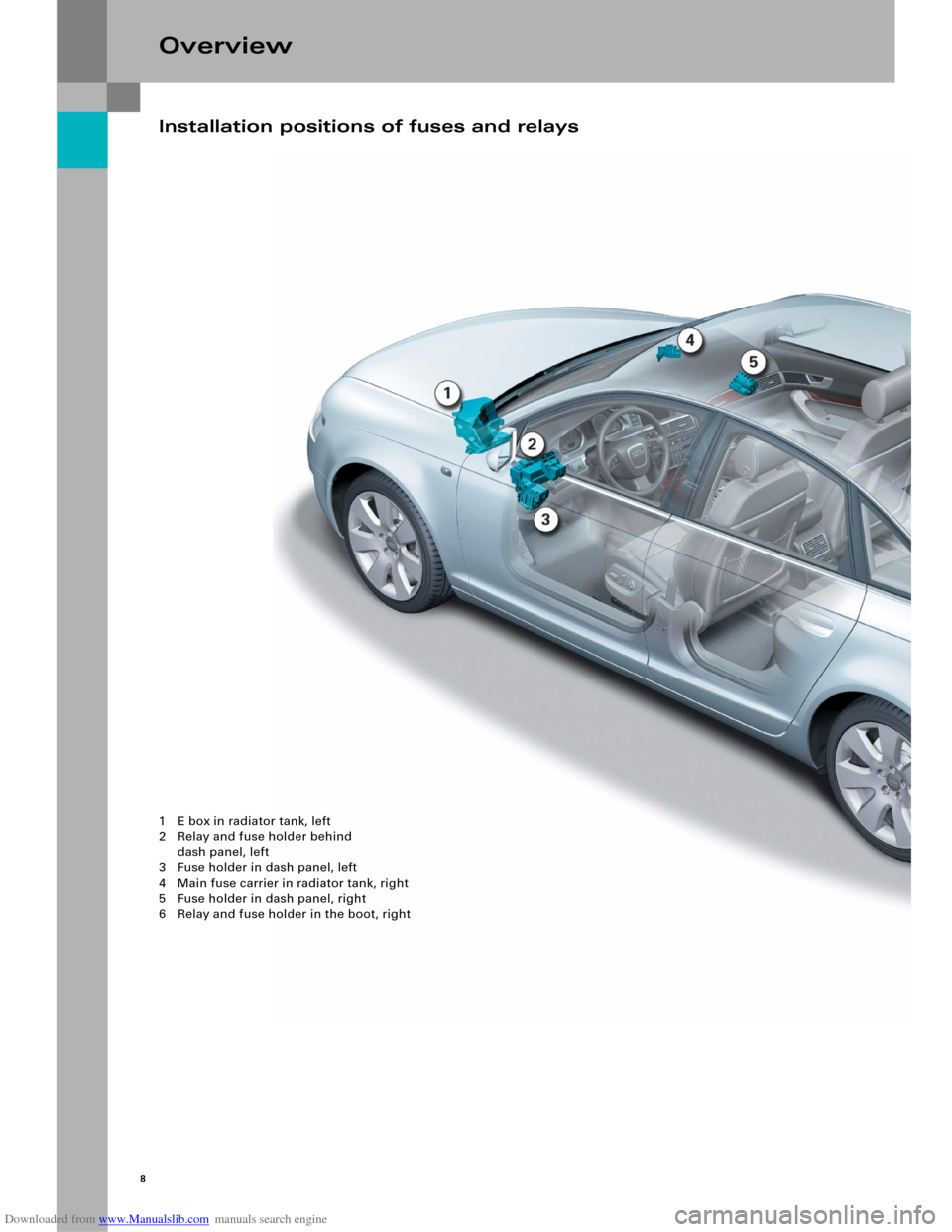
Installation positions of fuses and relays
1 E box in radiator tank, left
2 Relay and fuse holder behind
dash panel, left
3 Fuse holder in dash panel, left
4 Main fuse carrier in radiator tank, right
5 Fuse holder in dash panel, right
6 Relay and fuse holder in the boot, right
Page 12 of 92
Downloaded from www.Manualslib.com manuals search engine Convenience electricsFunction diagramLegend
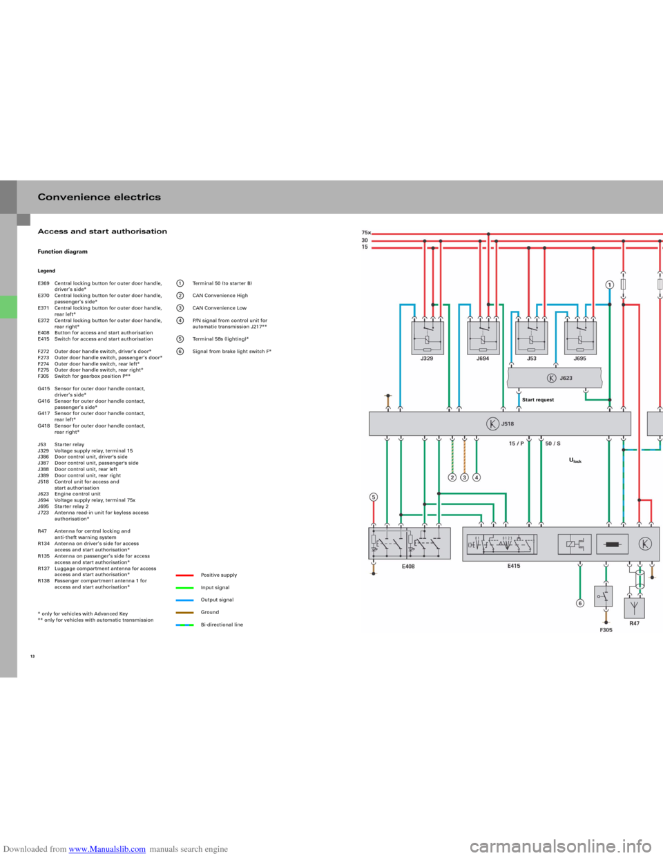
E369 Central locking button for outer door handle,
driver’s side*
E370 Central locking button for outer door handle,
passenger’s side*
E371 Central locking button for outer door handle,
rear left*
E372 Central locking button for outer door handle,
rear right*
E408 Button for access and start authorisation
E415 Switch for access and start authorisation
F272 Outer door handle switch, driver’s door*
F273 Outer door handle switch, passenger’s door*
F274 Outer door handle switch, rear left*
F275 Outer door handle switch, rear right*
F305 Switch for gearbox position P**
G415 Sensor for outer door handle contact,
driver’s side*
G416 Sensor for outer door handle contact,
passenger’s side*
G417 Sensor for outer door handle contact,
rear left*
G418 Sensor for outer door handle contact,
rear right*
J53 Starter relay
J329 Voltage supply relay, terminal 15
J386 Door control unit, driver's side
J387 Door control unit, passenger's side
J388 Door control unit, rear left
J389 Door control unit, rear right
J518 Control unit for access and
start authorisation
J623 Engine control unit
J694 Voltage supply relay, terminal 75x
J695 Starter relay 2
J723 Antenna read-in unit for keyless access
authorisation*
R47 Antenna for central locking and
anti-theft warning system
R134 Antenna on driver’s side for access
access and start authorisation*
R135 Antenna on passenger’s side for access
access and start authorisation*
R137 Luggage compartment antenna for access
access and start authorisation*
R138 Passenger compartment antenna 1 for
access and start authorisation*
* only for vehicles with Advanced Key
** only for vehicles with automatic transmission
1 Terminal 50 (to starter B)
2 CAN Convenience High
3 CAN Convenience Low
4 P/N signal from control unit for
automatic transmission J217**
5 Terminal 58s (lighting)*
6 Signal from brake light switch F*
Positive supply
Input signal
Output signal
Ground
Bi-directional line
13
Access and start authorisation
Start request
Ulock
Page 19 of 92
Downloaded from www.Manualslib.com manuals search engine 21
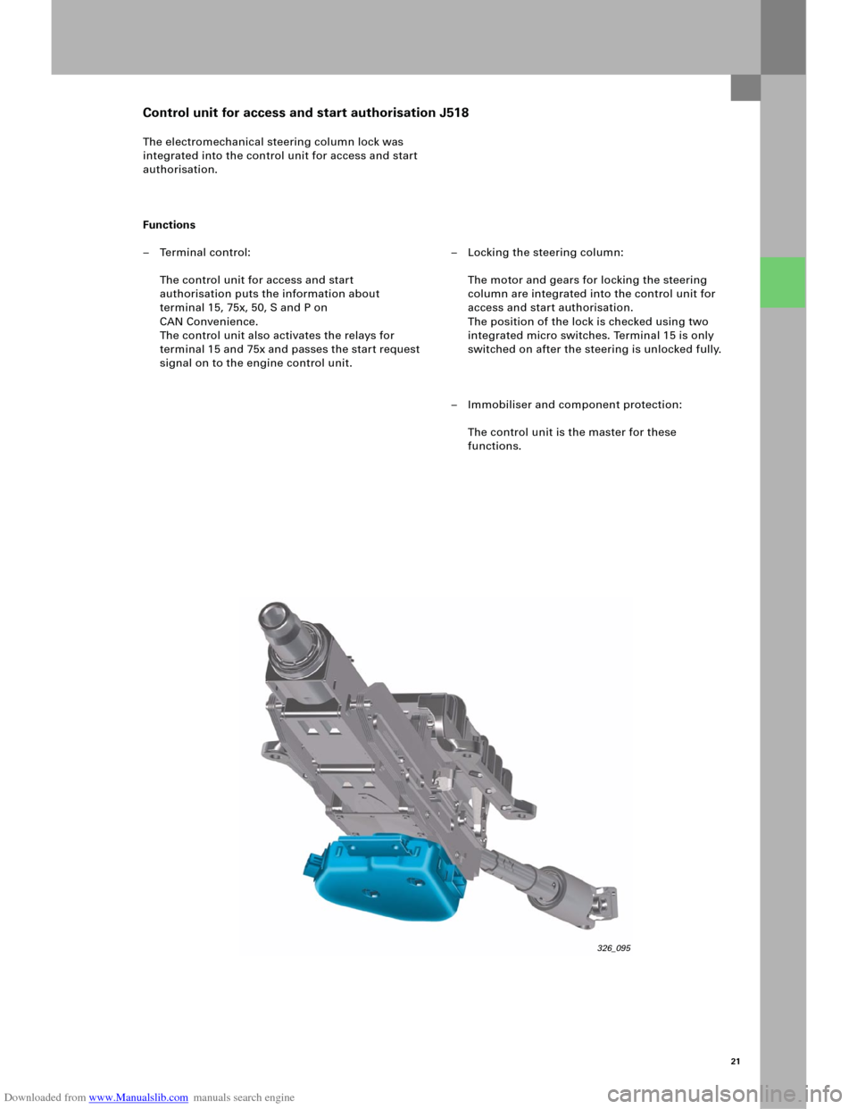
The electromechanical steering column lock was
integrated into the control unit for access and start
authorisation.
Functions
– Terminal control:
The control unit for access and start
authorisation puts the information about
terminal 15, 75x, 50, S and P on
CAN Convenience.
The control unit also activates the relays for
terminal 15 and 75x and passes the start request
signal on to the engine control unit.– Locking the steering column:
The motor and gears for locking the steering
column are integrated into the control unit for
access and start authorisation.
The position of the lock is checked using two
integrated micro switches. Terminal 15 is only
switched on after the steering is unlocked fully.
– Immobiliser and component protection:
The control unit is the master for these
functions.
Control unit for access and start authorisation J518
326_095
Page 39 of 92
Downloaded from www.Manualslib.com manuals search engine 41
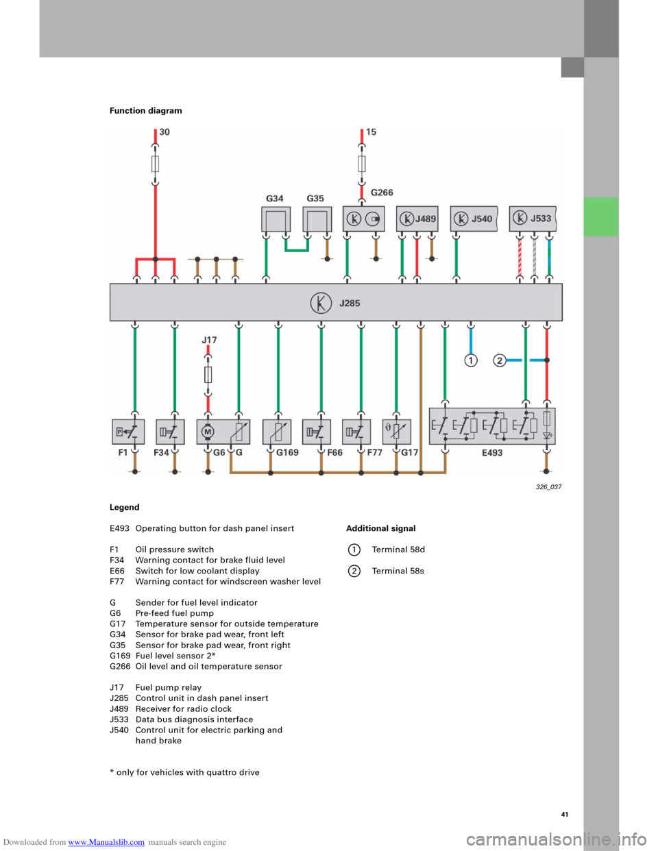
Function diagram
Legend
E493 Operating button for dash panel insert
F1 Oil pressure switch
F34 Warning contact for brake fluid level
E66 Switch for low coolant display
F77 Warning contact for windscreen washer level
G Sender for fuel level indicator
G6 Pre-feed fuel pump
G17 Temperature sensor for outside temperature
G34 Sensor for brake pad wear, front left
G35 Sensor for brake pad wear, front right
G169 Fuel level sensor 2*
G266 Oil level and oil temperature sensor
J17 Fuel pump relay
J285 Control unit in dash panel insert
J489 Receiver for radio clock
J533 Data bus diagnosis interface
J540 Control unit for electric parking and
hand brake
* only for vehicles with quattro drive
326_037
Additional signal
1 Terminal 58d
2 Terminal 58s
Page 42 of 92
Downloaded from www.Manualslib.com manuals search engine 44
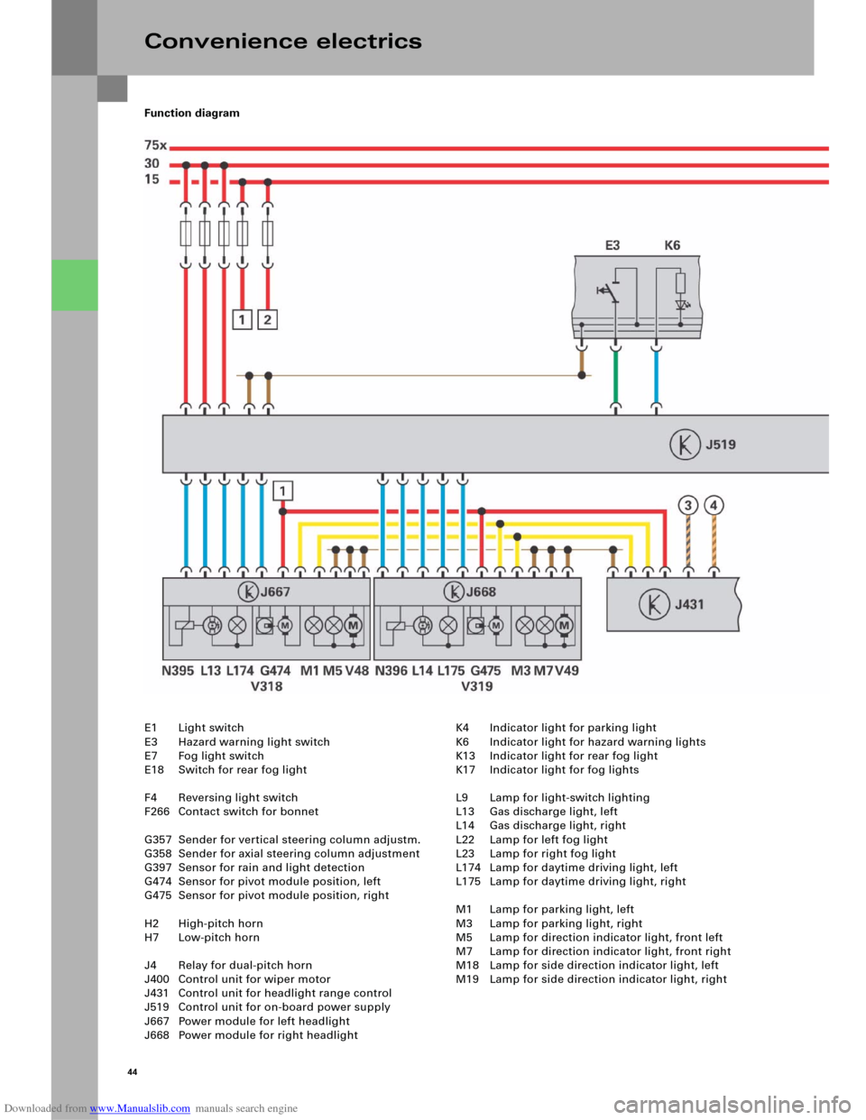
Function diagram
Convenience electrics
E1 Light switch
E3 Hazard warning light switch
E7 Fog light switch
E18 Switch for rear fog light
F4 Reversing light switch
F266 Contact switch for bonnet
G357 Sender for vertical steering column adjustm.
G358 Sender for axial steering column adjustment
G397 Sensor for rain and light detection
G474 Sensor for pivot module position, left
G475 Sensor for pivot module position, right
H2 High-pitch horn
H7 Low-pitch horn
J4 Relay for dual-pitch horn
J400 Control unit for wiper motor
J431 Control unit for headlight range control
J519 Control unit for on-board power supply
J667 Power module for left headlight
J668 Power module for right headlightK4 Indicator light for parking light
K6 Indicator light for hazard warning lights
K13 Indicator light for rear fog light
K17 Indicator light for fog lights
L9 Lamp for light-switch lighting
L13 Gas discharge light, left
L14 Gas discharge light, right
L22 Lamp for left fog light
L23 Lamp for right fog light
L174 Lamp for daytime driving light, left
L175 Lamp for daytime driving light, right
M1 Lamp for parking light, left
M3 Lamp for parking light, right
M5 Lamp for direction indicator light, front left
M7 Lamp for direction indicator light, front right
M18 Lamp for side direction indicator light, left
M19 Lamp for side direction indicator light, right
Page 44 of 92
Downloaded from www.Manualslib.com manuals search engine 46
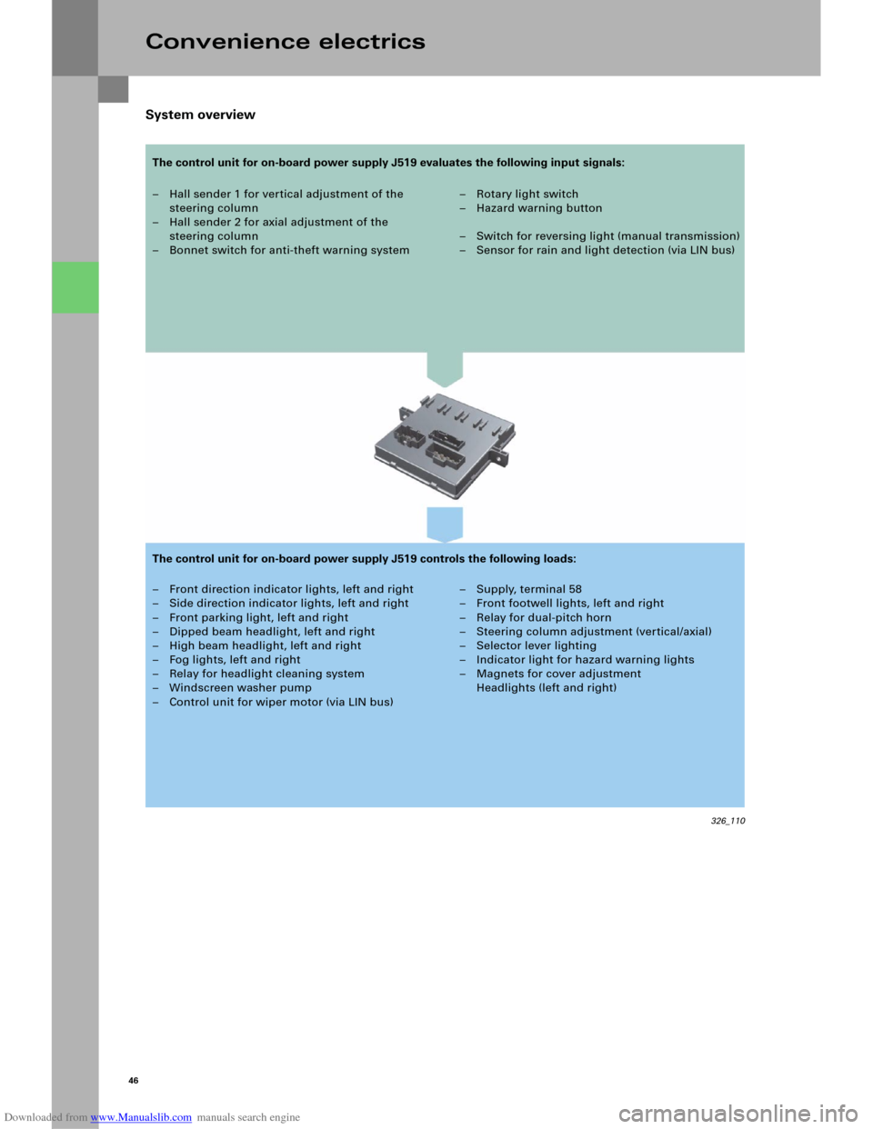
System overview
Convenience electrics
– Hall sender 1 for vertical adjustment of the
steering column
– Hall sender 2 for axial adjustment of the
steering column
– Bonnet switch for anti-theft warning system–Rotary light switch
–Hazard warning button
– Switch for reversing light (manual transmission)
– Sensor for rain and light detection (via LIN bus)
– Front direction indicator lights, left and right
– Side direction indicator lights, left and right
– Front parking light, left and right
– Dipped beam headlight, left and right
– High beam headlight, left and right
– Fog lights, left and right
– Relay for headlight cleaning system
– Windscreen washer pump
– Control unit for wiper motor (via LIN bus)– Supply, terminal 58
– Front footwell lights, left and right
– Relay for dual-pitch horn
– Steering column adjustment (vertical/axial)
– Selector lever lighting
– Indicator light for hazard warning lights
– Magnets for cover adjustment
Headlights (left and right)
326_110
The control unit for on-board power supply J519 evaluates the following input signals:
The control unit for on-board power supply J519 controls the following loads:
Page 45 of 92
Downloaded from www.Manualslib.com manuals search engine 47
Diagnosis
Basic settings
After the control unit for on-board power
supply J519 or the steering column or the switch for
steering column adjustment E167 is replaced, a
basic setting in axial and vertical position must be
implemented for the steering column.
Actuator test
An actuator test can be used to carry out the
following checks:
– Indicator light for hazard warning lights K6
– Lamp for parking light, left M1
– Lamp for parking light, right M3
– Lamp for dipped beam headlight, left M29
– Lamp for dipped beam headlight, right M31
– Lamp for high beam headlight, left M30
– Lamp for high beam headlight, right M32
– Lamp for left fog light L22
– Lamp for right fog light L23
– Lamp for daytime driving light, left L174
– Lamp for daytime driving light, right L175
– Direction indicator lights, left
– Direction indicator lights, right
– Footwell light, left W9
– Footwell light, right W10
– Wiper, top turning position
– Wiper, bottom turning position
– Windscreen washer pump V5
– Relay for dual-pitch horn
–Terminal 58
Coding
The control unit for on-board power supply J519 can
be coded for the functions
–Daytime driving light,
– Driving light assistant,
– Headlight type,
– Footwell lighting and
–Country versions
using the diagnosis tester.
Note
The actuator test can be performed either
sequentially (in sequence) or selectively
(individual selection).