2005 AUDI A6 door lock
[x] Cancel search: door lockPage 12 of 92
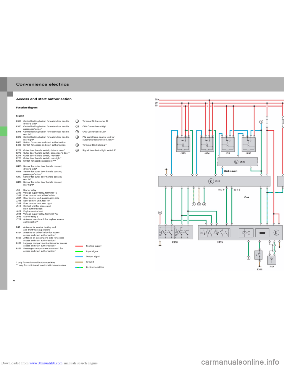
Downloaded from www.Manualslib.com manuals search engine Convenience electricsFunction diagramLegend
E369 Central locking button for outer door handle,
driver’s side*
E370 Central locking button for outer door handle,
passenger’s side*
E371 Central locking button for outer door handle,
rear left*
E372 Central locking button for outer door handle,
rear right*
E408 Button for access and start authorisation
E415 Switch for access and start authorisation
F272 Outer door handle switch, driver’s door*
F273 Outer door handle switch, passenger’s door*
F274 Outer door handle switch, rear left*
F275 Outer door handle switch, rear right*
F305 Switch for gearbox position P**
G415 Sensor for outer door handle contact,
driver’s side*
G416 Sensor for outer door handle contact,
passenger’s side*
G417 Sensor for outer door handle contact,
rear left*
G418 Sensor for outer door handle contact,
rear right*
J53 Starter relay
J329 Voltage supply relay, terminal 15
J386 Door control unit, driver's side
J387 Door control unit, passenger's side
J388 Door control unit, rear left
J389 Door control unit, rear right
J518 Control unit for access and
start authorisation
J623 Engine control unit
J694 Voltage supply relay, terminal 75x
J695 Starter relay 2
J723 Antenna read-in unit for keyless access
authorisation*
R47 Antenna for central locking and
anti-theft warning system
R134 Antenna on driver’s side for access
access and start authorisation*
R135 Antenna on passenger’s side for access
access and start authorisation*
R137 Luggage compartment antenna for access
access and start authorisation*
R138 Passenger compartment antenna 1 for
access and start authorisation*
* only for vehicles with Advanced Key
** only for vehicles with automatic transmission
1 Terminal 50 (to starter B)
2 CAN Convenience High
3 CAN Convenience Low
4 P/N signal from control unit for
automatic transmission J217**
5 Terminal 58s (lighting)*
6 Signal from brake light switch F*
Positive supply
Input signal
Output signal
Ground
Bi-directional line
13
Access and start authorisation
Start request
Ulock
Page 15 of 92
Downloaded from www.Manualslib.com manuals search engine 17
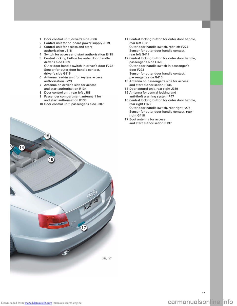
326_147
1 Door control unit, driver's side J386
2 Control unit for on-board power supply J519
3 Control unit for access and start
authorisation J518
4 Switch for access and start authorisation E415
5 Central locking button for outer door handle,
driver's side E369
Outer door handle switch in driver’s door F272
Sensor for outer door handle contact,
driver’s side G415
6 Antenna read-in unit for keyless access
authorisation J723
7 Antenna on driver’s side for access
and start authorisation R134
8 Door control unit, rear left J388
9 Passenger compartment antenna 1 for
and start authorisation R138
10 Door control unit, passenger's side J38711 Central locking button for outer door handle,
rear left E371
Outer door handle switch, rear left F274
Sensor for outer door handle contact,
rear left G417
12 Central locking button for outer door handle,
passenger’s side E370
Outer door handle switch in passenger’s
door F273
Sensor for outer door handle contact,
passenger's side G416
13 Antenna on passenger’s side for access
and start authorisation R135
14 Door control unit, rear right J389
15 Antenna for central locking and
anti-theft warning system R47
16 Central locking button for outer door handle,
rear right E372
Outer door handle switch, rear right F275
Sensor for outer door handle contact, rear
right G418
17 Boot antenna for access
and start authorisation R137
Page 21 of 92
Downloaded from www.Manualslib.com manuals search engine 23
Vehicl e ke y
The key has a mechanically coded hinged bit for the
lock cylinder in the driver’s door and the tailgate/
boot lid. The transponder function is integrated into
the electronics and also works without a battery.
An integrated battery powers the electronics for the
radio remote control and Advanced Key functions.
A new feature here is the bi-directional data
exchange between the radio-control key and the
control unit for access and start authorisation via
the antenna for central locking and anti-theft
warning system R47. This is used to transfer the
status of the central locking system into the key.
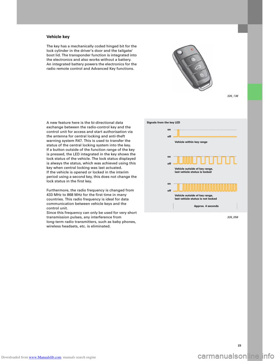
If a button outside of the function range of the key
is pressed, the LED integrated in the key shows the
lock status of the vehicle. The lock status displayed
is always the status, which was achieved using this
key when central locking was last actuated.
If the vehicle is opened or locked in the interim
period using a second key, this does not change the
lock status in the first key.
Furthermore, the radio frequency is changed from
433 MHz to 868 MHz for the first time in many
countries. This radio frequency is ideal for data
communication between vehicle keys and the
control unit.
Since this frequency can only be used for very short
transmission pulses, any interference from
long-term radio transmitters, such as baby phones,
wireless headsets, etc. is eliminated.
326_138
326_058 Vehicle within key range
Vehicle outside of key range,
last vehicle status is locked Signals from the key LED
Vehicle outside of key range,
last vehicle status is not locked
Approx. 4 seconds on
off
on
off
on
off
Page 22 of 92
Downloaded from www.Manualslib.com manuals search engine 24
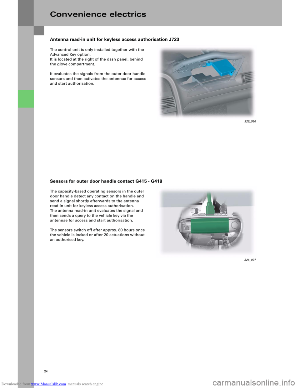
The control unit is only installed together with the
Advanced Key option.
It is located at the right of the dash panel, behind
the glove compartment.
It evaluates the signals from the outer door handle
sensors and then activates the antennae for access
and start authorisation.
The capacity-based operating sensors in the outer
door handle detect any contact on the handle and
send a signal shortly afterwards to the antenna
read-in unit for keyless access authorisation.
The antenna read-in unit evaluates the signal and
then sends a query to the vehicle key via the
antennae for access and start authorisation.
The sensors switch off after approx. 80 hours once
the vehicle is locked or after 20 actuations without
an authorised key.
Convenience electrics
326_097
Antenna read-in unit for keyless access authorisation J723
Sensors for outer door handle contact G415 - G418
326_096
Page 24 of 92
Downloaded from www.Manualslib.com manuals search engine 26
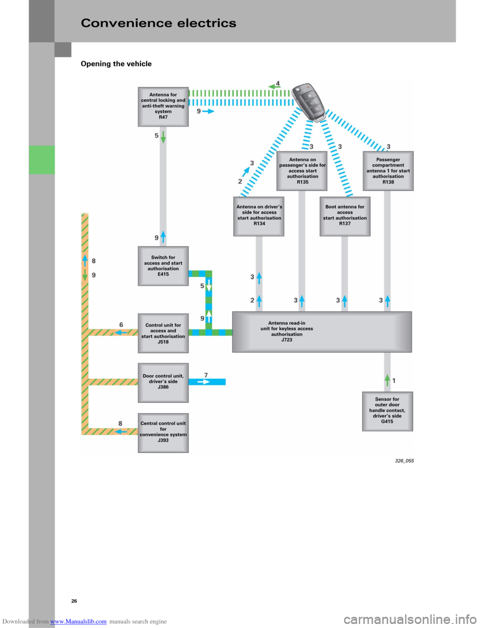
Opening the vehicle
Convenience electrics
326_055 Antenna for
central locking and
anti-theft warning
system
R47
Antenna on driver’s
side for access
start authorisation
R134Antenna on
passenger’s side for
access start
authorisation
R135Passeng er
compartment
antenna 1 for start
authorisation
R138
Boot antenna for
access
start authorisation
R137
Switch for
access and start
authorisation
E415
Antenna read-in
unit for keyless access
authorisation
J723 Control unit for
access and
start authorisation
J518
Door control unit,
driver’s side
J386
Central control unit
for
convenience system
J393Sensor for
outer door
handle contact,
driver’s side
G415
Page 25 of 92
Downloaded from www.Manualslib.com manuals search engine 27
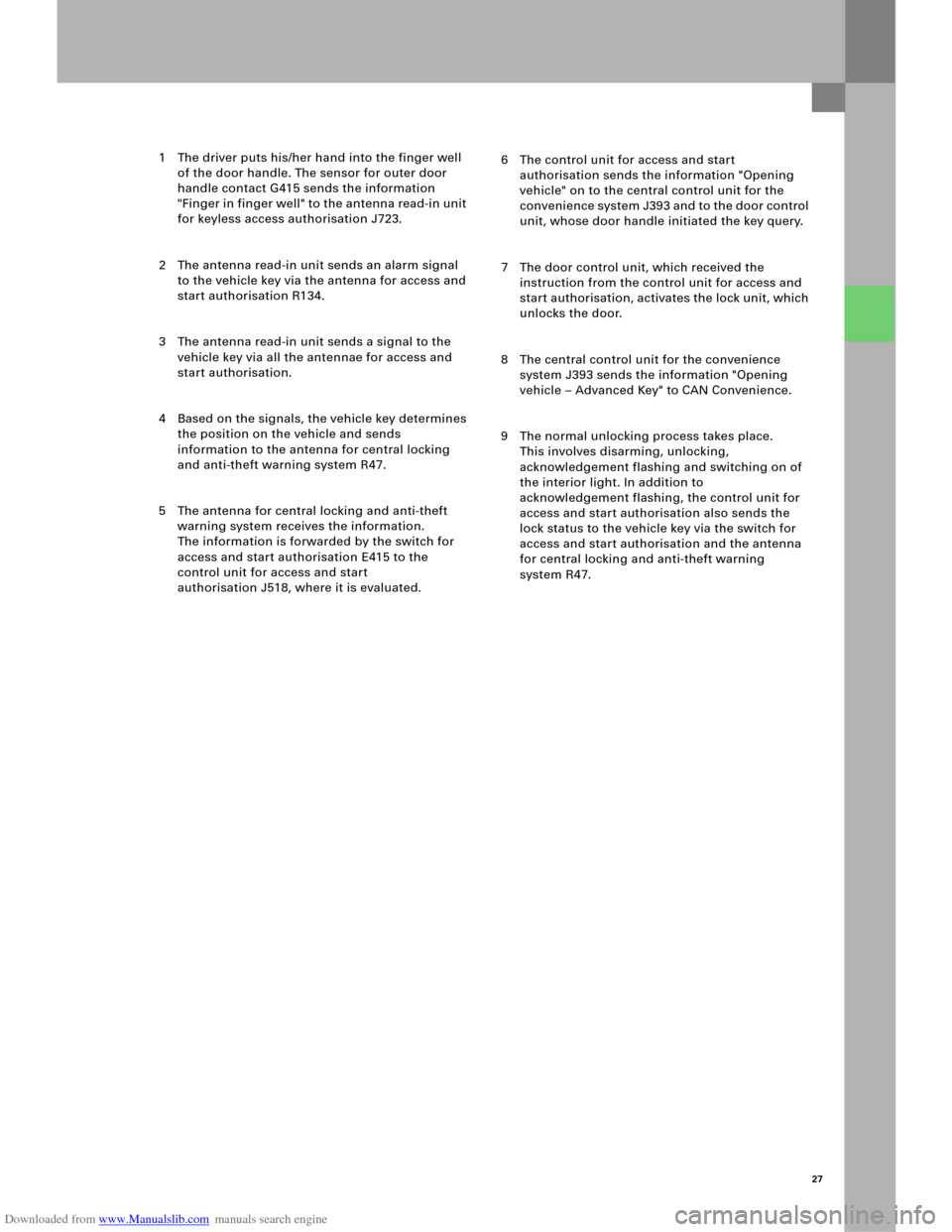
1 The driver puts his/her hand into the finger well
of the door handle. The sensor for outer door
handle contact G415 sends the information
"Finger in finger well" to the antenna read-in unit
for keyless access authorisation J723.
2 The antenna read-in unit sends an alarm signal
to the vehicle key via the antenna for access and
start authorisation R134.
3 The antenna read-in unit sends a signal to the
vehicle key via all the antennae for access and
start authorisation.
4 Based on the signals, the vehicle key determines
the position on the vehicle and sends
information to the antenna for central locking
and anti-theft warning system R47.
5 The antenna for central locking and anti-theft
warning system receives the information.
The information is forwarded by the switch for
access and start authorisation E415 to the
control unit for access and start
authorisation J518, where it is evaluated.6 The control unit for access and start
authorisation sends the information "Opening
vehicle" on to the central control unit for the
convenience system J393 and to the door control
unit, whose door handle initiated the key query.
7 The door control unit, which received the
instruction from the control unit for access and
start authorisation, activates the lock unit, which
unlocks the door.
8 The central control unit for the convenience
system J393 sends the information "Opening
vehicle – Advanced Key" to CAN Convenience.
9 The normal unlocking process takes place.
This involves disarming, unlocking,
acknowledgement flashing and switching on of
the interior light. In addition to
acknowledgement flashing, the control unit for
access and start authorisation also sends the
lock status to the vehicle key via the switch for
access and start authorisation and the antenna
for central locking and anti-theft warning
system R47.
Page 52 of 92
Downloaded from www.Manualslib.com manuals search engine 54
The tilt sensor for the anti-theft warning system is
integrated directly in control unit 2 for on-board
power supply J520 in the new Audi A6 ‘05.
The fluid-filled sensor registers changes in the
vehicle tilt both transversely and longitudinally,
thereby preventing incorrect triggering as a result of
shaking through viscous fluid and electronic delay.
The current tilt values can be read out using
measured-value blocks.
Diagnosis
– Measured-value blocks
Measured-value blocks are available for the
following functions:
– Servotronic
– Sliding roof
– Tilt angle
–Actuator test
Checks can be carried out for the following
functions, depending on the version:
– Glove compartment release
– Servotronic valve
– Sliding roof activation (can be measured
using a multimeter on the on-board power
supply control unit, sliding roof does not
open, however, if it is not released by the
central control unit for the convenience
system)
–Coding
The High-Line version of control unit 2 for
on-board power supply J520 must be coded for
the following functions:
– Tilt sensor (with or without)
– Sliding roof (with or without)
Convenience electrics
Note
The tilt sensor function can be switched off
using a button in the driver’s door panel.
Reference
For further information on the tilt sensor
function, please refer to the SSP 254,
Audi A4 ‘01 – Technology.
Tilt sensor for anti-theft warning system
Page 54 of 92
Downloaded from www.Manualslib.com manuals search engine 56
326_121
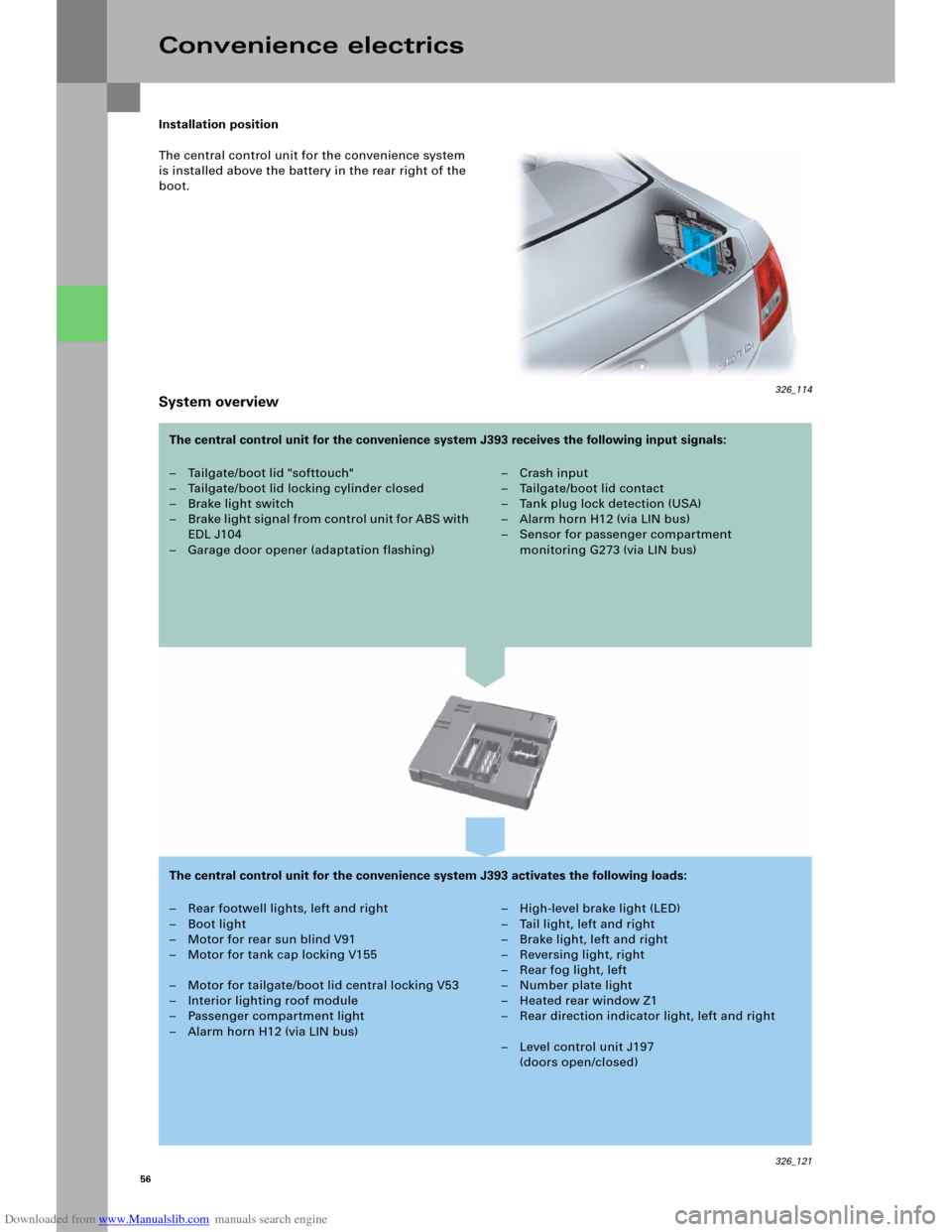
Installation position
The central control unit for the convenience system
is installed above the battery in the rear right of the
boot.
System overview
Convenience electrics
– Tailgate/boot lid "softtouch"
– Tailgate/boot lid locking cylinder closed
– Brake light switch
– B rake li ght signal from control u ni t fo r ABS with
EDL J104
– Garage door opener (adaptation flashing)– Crash input
– Tailgate/boot lid contact
–Tank plug lock detection (USA)
– Alarm horn H12 (via LIN bus)
– Sensor for passenger compartment
monitoring G273 (via LIN bus)
– Rear footwell lights, left and right
– Boot light
– Motor for rear sun blind V91
– Motor for tank cap locking V155
– Motor for tailgate/boot lid central locking V53
– Interior lighting roof module
– Passenger compartment light
– Alarm horn H12 (via LIN bus)– High-level brake light (LED)
– Tail light, left and right
–Brake light, left and right
– Reversing light, right
–Rear fog light, left
– Number plate light
– Heated rear window Z1
– Rear direction indicator light, left and right
– Level control unit J197
(doors open/closed) The central control unit for the convenience system J393 receives the following input signals:
The central control unit for the convenience system J393 activates the following loads:
326_114