Page 33 of 104

INSTRUMENT AND CONTROL FUNCTIONS
3-19
3
CAUTION:
ECA11600
Some helmets may contact the muf-
fler when secured to the right side
helmet holder because of their size
or shape. Be sure that your helmet
does not contact the muffler when itis secured to the helmet holder.
To release a helmet from a helmet
holder
Remove the passenger seat, remove
the helmet from the helmet holder, and
then install the seat.
EAU14431
Storage compartment The storage compartment is located
under the passenger seat. (See page
3-17.)
This storage compartment is designed
to hold a genuine Yamaha U-LOCK.
(Other locks may not fit.)
WARNING
EWA10961
�
Do not exceed the load limit of 3
kg (7 lb) for the storage com-
partment.
�
Do not exceed the maximum
load of 193 kg (425 lb) for the ve-hicle.
To place a U-LOCK in the storage
compartment
1. Remove the rubber cap from the
hole at the bottom of the storage
compartment, and then store it in a
safe place to prevent losing the
cap.
2. Insert the ends of the U-LOCK bar
into the holes at the bottom of the
storage compartment as shown.
3. Place the lock of the U-LOCK in
the location shown.
4. Securely fasten the U-LOCK bar
and lock with the strap as shown.
NOTE:�
When the U-LOCK is not in the
storage compartment, be sure to
cover the hole at the bottom of the
storage compartment with the rub-
ber cap.
1. U-LOCK bar (optional)
2. Lock of U-LOCK (optional)
3. Strap
4. Rubber cap
5SLE1.book Page 19 Friday, August 1, 2003 4:09 PM
Page 34 of 104

INSTRUMENT AND CONTROL FUNCTIONS
3-20
3
�
When storing items in the storage
compartment, be sure to wrap
them in a plastic bag to preventlosing them.
EAU14761
Adjusting the front fork This front fork is equipped with spring
preload adjusting bolts, rebound damp-
ing force adjusting screws and com-
pression damping force adjusting
screws.
WARNING
EWA10180
Always adjust both fork legs equal-
ly, otherwise poor handling and lossof stability may result.
Spring preload
To increase the spring preload and
thereby harden the suspension, turn
the adjusting bolt on each fork leg in di-
rection (a). To decrease the spring pre-load and thereby soften the
suspension, turn the adjusting bolt on
each fork leg in direction (b).
NOTE:Align the appropriate groove on the ad-
justing mechanism with the top of thefront fork cap bolt.
1. Spring preload adjusting bolt
1. Current setting
2. Front fork cap boltSpring preload setting:
Minimum (soft):
8
Standard:
7
Maximum (hard):
1
5SLE1.book Page 20 Friday, August 1, 2003 4:09 PM
Page 35 of 104
")
INSTRUMENT AND CONTROL FUNCTIONS
3-21
3 Rebound damping force
To increase the rebound damping force
and thereby harden the rebound damp-
ing, turn the adjusting screw on each
fork leg in direction (a). To decrease the
rebound damping force and thereby
soften the rebound damping, turn the
adjusting screw on each fork leg in di-
rection (b).Compression damping force
To increase the compression damping
force and thereby harden the compres-
sion damping, turn the adjusting screw
on each fork leg in direction (a). To de-
crease the compression damping force
and thereby soften the compression
damping, turn the adjusting screw on
each fork leg in direction (b).
CAUTION:
ECA10100
Never attempt to turn an adjusting
mechanism beyond the maximum orminimum settings.NOTE:Although the total number of clicks of a
damping force adjusting mechanism
may not exactly match the above spec-
ifications due to small differences in
production, the actual number of clicks
always represents the entire adjusting
range. To obtain a precise adjustment,
it would be advisable to check the num-
ber of clicks of each damping force ad-
justing mechanism and to modify thespecifications as necessary.
1. Rebound damping force adjusting screwRebound damping setting:
Minimum (soft):
10 click(s) in direction (b)*
Standard:
9 click(s) in direction (b)*
Maximum (hard):
1 click(s) in direction (b)*
* With the adjusting screw fully turned
in direction (a)
1. Compression damping force adjusting screw
Compression damping setting:
Minimum (soft):
9 click(s) in direction (b)*
Standard:
7 click(s) in direction (b)*
Maximum (hard):
1 click(s) in direction (b)*
* With the adjusting screw fully turned
in direction (a)
5SLE1.book Page 21 Friday, August 1, 2003 4:09 PM
Page 36 of 104

INSTRUMENT AND CONTROL FUNCTIONS
3-22
3
EAU15051
Adjusting the shock absorber
assembly This shock absorber assembly is
equipped with a spring preload adjust-
ing ring and rebound and compression
damping force adjusting screws.CAUTION:
ECA10100
Never attempt to turn an adjusting
mechanism beyond the maximum orminimum settings.
Spring preloadTo increase the spring preload and
thereby harden the suspension, turn
the adjusting ring in direction (a). To de-
crease the spring preload and thereby
soften the suspension, turn the adjust-
ing ring in direction (b).
Rebound damping force
To increase the rebound damping force
and thereby harden the rebound damp-
ing, turn the adjusting screw in direction(a). To decrease the rebound damping
force and thereby soften the rebound
damping, turn the adjusting screw in di-
rection (b).
Compression damping force
To increase the compression damping
force and thereby harden the compres-
sion damping, turn the adjusting screw1. Spring preload adjusting ring
2. Special wrench
3. Position indicator
Spring preload setting:
Minimum (soft):
1
Standard:
4
Maximum (hard):
91. Rebound damping force adjusting screw
Rebound damping setting:
Minimum (soft):
20 click(s) in direction (b)*
Standard:
10 click(s) in direction (b)*
Maximum (hard):
5 click(s) in direction (b)*
* With the adjusting screw fully turned
in direction (a)1. Compression damping force adjusting screw
5SLE1.book Page 22 Friday, August 1, 2003 4:09 PM
Page 37 of 104
. To decrease the com-
pression damping force and thereby
soften the compression damping, turn
the adjusting screw in direction (b).
NOTE:
Altho")
INSTRUMENT AND CONTROL FUNCTIONS
3-23
3 in direction (a). To decrease the com-
pression damping force and thereby
soften the compression damping, turn
the adjusting screw in direction (b).
NOTE:
Although the total number of clicks of a
damping force adjusting mechanism
may not exactly match the above spec-
ifications due to small differences in
production, the actual number of clicks
always represents the entire adjusting
range. To obtain a precise adjustment,
it would be advisable to check the num-
ber of clicks of each damping force ad-
justing mechanism and to modify thespecifications as necessary.
WARNING
EWA10220
This shock absorber contains highly
pressurized nitrogen gas. For prop-
er handling, read and understand
the following information before
handling the shock absorber. The
manufacturer cannot be held re-
sponsible for property damage or
personal injury that may result from
improper handling.�
Do not tamper with or attempt to
open the gas cylinder.
�
Do not subject the shock ab-
sorber to an open flame or other
high heat sources, otherwise it
may explode due to excessive
gas pressure.
�
Do not deform or damage the
gas cylinder in any way, as this
will result in poor damping per-
formance.
�
Always have a Yamaha dealerservice the shock absorber.
EAU15181
Luggage strap holders There are four luggage strap holders on
the bottom of the passenger seat. To
use the strap holders, remove the pas-
senger seat, unhook the straps from
the hooks, and then install the seat with
the straps hanging out from under the
passenger seat. (See page 3-17.)
Compression damping setting:
Minimum (soft):
20 click(s) in direction (b)*
Standard:
10 click(s) in direction (b)*
Maximum (hard):
1 click(s) in direction (b)*
* With the adjusting screw fully turned
in direction (a)
1. Luggage strap holder
2. Hook
5SLE1.book Page 23 Friday, August 1, 2003 4:09 PM
Page 38 of 104

INSTRUMENT AND CONTROL FUNCTIONS
3-24
3
EAU15300
Sidestand The sidestand is located on the left side
of the frame. Raise the sidestand or
lower it with your foot while holding the
vehicle upright.NOTE:The built-in sidestand switch is part of
the ignition circuit cut-off system, which
cuts the ignition in certain situations.
(See further down for an explanation ofthe ignition circuit cut-off system.)
WARNING
EWA10240
The vehicle must not be ridden with
the sidestand down, or if the side-
stand cannot be properly moved up
(or does not stay up), otherwise the
sidestand could contact the ground
and distract the operator, resulting
in a possible loss of control.
Yamaha’s ignition circuit cut-off
system has been designed to assist
the operator in fulfilling the respon-
sibility of raising the sidestand be-
fore starting off. Therefore, check
this system regularly as describedbelow and have a Yamaha dealer re-
pair it if it does not function proper-
ly.
EAU15311
Ignition circuit cut-off system The ignition circuit cut-off system (com-
prising the sidestand switch, clutch
switch and neutral switch) has the fol-
lowing functions.�
It prevents starting when the trans-
mission is in gear and the side-
stand is up, but the clutch lever is
not pulled.
�
It prevents starting when the trans-
mission is in gear and the clutch le-
ver is pulled, but the sidestand is
still down.
�
It cuts the running engine when the
transmission is in gear and the sid-
estand is moved down.
Periodically check the operation of the
ignition circuit cut-off system according
to the following procedure.WARNING
EWA10250
If a malfunction is noted, have a
Yamaha dealer check the system be-fore riding.
5SLE1.book Page 24 Friday, August 1, 2003 4:09 PM
Page 39 of 104

INSTRUMENT AND CONTROL FUNCTIONS
3-25
3
With the engine turned off:
1. Move the sidestand down.
2. Make sure that the engine stop switch is turned on.
3. Turn the key on.
4. Shift the transmission into the neutral position.
5. Push the start switch.
Does the engine start?
With the engine still running:
6. Move the sidestand up.
7. Keep the clutch lever pulled.
8. Shift the transmission into gear.
9. Move the sidestand down.
Does the engine stall?
After the engine has stalled:
10. Move the sidestand up.
11. Keep the clutch lever pulled.
12. Push the start switch.
Does the engine start?
The system is OK. The motorcycle can be ridden.
This check is most reliable if performed with
a warmed-up engine.The neutral switch may be defective.
The motorcycle should not be ridden until
checked by a Yamaha dealer.
The sidestand switch may be defective.
The motorcycle should not be ridden until
checked by a Yamaha dealer.
The clutch switch may be defective.
The motorcycle should not be ridden until
checked by a Yamaha dealer.
YES NO YES NO YES NONOTE:
5SLE1.book Page 25 Friday, August 1, 2003 4:09 PM
Page 40 of 104
PRE-OPERATION CHECKS
4-1
4
EAU15591
The condition of a vehicle is the owner’s responsibility. Vital components can start to deteriorate quickly and unexpectedly,
even if the vehicle remains unused (for example, as a result of exposure to the elements). Any damage, fluid leakage or loss
of tire air pressure could have serious consequences. Therefore, it is very important, in addition to a thorough visual inspec-
tion, to check the following points before each ride.NOTE:Pre-operation checks should be made each time the vehicle is used. Such an inspection can be accomplished in a very shorttime; and the added safety it assures is more than worth the time involved.
WARNING
EWA11150
If any item in the Pre-operation check list is not working properly, have it inspected and repaired before operatingthe vehicle.5SLE1.book Page 1 Friday, August 1, 2003 4:09 PM
 1
1 2
2 3
3 4
4 5
5 6
6 7
7 8
8 9
9 10
10 11
11 12
12 13
13 14
14 15
15 16
16 17
17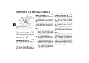 18
18 19
19 20
20 21
21 22
22 23
23 24
24 25
25 26
26 27
27 28
28 29
29 30
30 31
31 32
32 33
33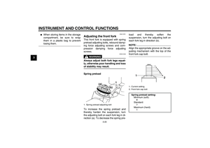 34
34 35
35 36
36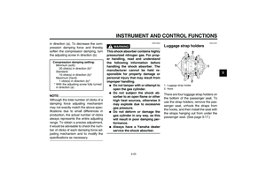 37
37 38
38 39
39 40
40 41
41 42
42 43
43 44
44 45
45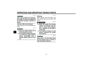 46
46 47
47 48
48 49
49 50
50 51
51 52
52 53
53 54
54 55
55 56
56 57
57 58
58 59
59 60
60 61
61 62
62 63
63 64
64 65
65 66
66 67
67 68
68 69
69 70
70 71
71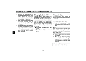 72
72 73
73 74
74 75
75 76
76 77
77 78
78 79
79 80
80 81
81 82
82 83
83 84
84 85
85 86
86 87
87 88
88 89
89 90
90 91
91 92
92 93
93 94
94 95
95 96
96 97
97 98
98 99
99 100
100 101
101 102
102 103
103