Page 57 of 104

PERIODIC MAINTENANCE AND MINOR REPAIR
6-11
6
NOTE:
Make sure that the O-ring is properlyseated.
8. Install the new oil filter cartridge
with an oil filter wrench, and then
tighten it to the specified torque
with a torque wrench.9. Install the cowling.
10. Install the coolant reservoir cover
by installing the bolts.
11. Install the engine oil drain bolt, and
then tighten it to the specified
torque.
NOTE:Check the washer for damage and re-place it if necessary.12. Add the specified amount of the
recommended engine oil, and then
install and tighten the oil filler cap.
CAUTION:
ECA11620
�
In order to prevent clutch slip-
page (since the engine oil also
lubricates the clutch), do not
mix any chemical additives. Do
not use oils with a diesel speci-
fication of “CD” or oils of a high-
er quality than specified. In
addition, do not use oils labeled
“ENERGY CONSERVING II” or
higher.
�
Make sure that no foreign mate-rial enters the crankcase.
1. O-ring
1. Torque wrench
Tightening torque:
Oil filter cartridge:
17 Nm (1.7 m·kgf, 12 ft·lbf)
Tightening torque:
Engine oil drain bolt:
43 Nm (4.3 m·kgf, 31 ft·lbf)
Recommended engine oil:
See page 8-1.
Oil quantity:
Without oil filter cartridge replace-
ment:
2.40 L (2.54 US qt) (2.11 Imp.qt)
With oil filter cartridge replacement:
2.60 L (2.75 US qt) (2.29 Imp.qt)
5SLE1.book Page 11 Friday, August 1, 2003 4:09 PM
Page 58 of 104

PERIODIC MAINTENANCE AND MINOR REPAIR
6-12
613. Start the engine, and then let it idle
for several minutes while checking
it for oil leakage. If oil is leaking, im-
mediately turn the engine off and
check for the cause.
NOTE:After the engine is started, the engine
oil level warning light should go off if theoil level is sufficient.CAUTION:
ECA10400
If the oil level warning light flickers
or remains on, immediately turn the
engine off and have a Yamaha dealercheck the vehicle.
14. Turn the engine off, and then
check the oil level and correct it if
necessary.
EAU20070
Coolant The coolant level should be checked
before each ride. In addition, the cool-
ant must be changed at the intervals
specified in the periodic maintenance
and lubrication chart.
EAU20111
To check the coolant level
1. Place the vehicle on a level sur-
face and hold it in an upright posi-
tion.NOTE:�
The coolant level must be checked
on a cold engine since the level
varies with engine temperature.
�
Make sure that the vehicle is posi-
tioned straight up when checking
the coolant level. A slight tilt to theside can result in a false reading.
2. Check the coolant level in the cool-
ant reservoir.
NOTE:The coolant should be between theminimum and maximum level marks.3. If the coolant is at or below the
minimum level mark, remove the
coolant reservoir cover by remov-
ing the bolts, remove the reservoir
cap, and then add coolant to the
maximum level mark.
1. Maximum level mark
2. Minimum level mark
1. Coolant reservoir cover
2. Bolt
5SLE1.book Page 12 Friday, August 1, 2003 4:09 PM
Page 59 of 104

PERIODIC MAINTENANCE AND MINOR REPAIR
6-13
6
CAUTION:
ECA10470
�
If coolant is not available, use
distilled water or soft tap water
instead. Do not use hard water
or salt water since it is harmful
to the engine.
�
If water has been used instead
of coolant, replace it with cool-
ant as soon as possible, other-
wise the engine may not be
sufficiently cooled and the cool-
ing system will not be protected
against frost and corrosion.
�
If water has been added to the
coolant, have a Yamaha dealer
check the antifreeze content of
the coolant as soon as possible,
otherwise the effectiveness ofthe coolant will be reduced.WARNING
EWA10380
Never attempt to remove the radiatorcap when the engine is hot.
4. Install the reservoir cap, and then
install the coolant reservoir cover
by installing the bolts.NOTE:�
The radiator fan is automatically
switched on or off according to the
coolant temperature in the radia-
tor.
�
If the engine overheats, see page6-43 for further instructions.
EAU20342
To change the coolant
1. Place the vehicle on a level sur-
face and let the engine cool if nec-
essary.2. Remove panel A and cowling A.
(See page 6-6.)
3. Place a container under the engine
to collect the used coolant.
4. Loosen the clamp screw, and then
disconnect the air intake duct.
5. Remove the radiator cap.
WARNING
EWA10380
Never attempt to remove the radiatorcap when the engine is hot.
1. Coolant reservoir capCoolant reservoir capacity (up to the
maximum level mark):
0.25 L (0.26 US qt) (0.22 Imp.qt)
1. Clamp screw
2. Air intake duct
5SLE1.book Page 13 Friday, August 1, 2003 4:09 PM
Page 60 of 104

PERIODIC MAINTENANCE AND MINOR REPAIR
6-14
66. Remove the coolant drain bolt to
drain the cooling system.
7. Loosen the clamp screw, and then
disconnect the radiator hose to
drain the radiator.8. Remove the coolant reservoir cov-
er by removing the bolts.
9. Remove cowling B. (See page
6-6.)
10. Pull the fuel hoses upward to re-
move them from the guide.11. Remove the coolant reservoir by
removing the bolts.
12. Remove the coolant reservoir cap,
and then turn the coolant reservoir
upside down to empty it.
13. After the coolant is completely
drained, thoroughly flush the cool-
ing system with clean tap water.
14. Install the coolant reservoir by in-
stalling the bolts.
15. Connect the radiator hose, and
then tighten the clamp screw.
16. Install the coolant drain bolt, and
then tighten it to the specified
torque.
1. Radiator cap
1. Coolant drain bolt
2. Clamp screw
1. Coolant reservoir cover
2. Bolt
1. Fuel tank breather hose
2. Fuel tank overflow hose
1. Coolant reservoir cap
2. Coolant reservoir
3. Bolt
5SLE1.book Page 14 Friday, August 1, 2003 4:09 PM
Page 61 of 104

PERIODIC MAINTENANCE AND MINOR REPAIR
6-15
6
NOTE:Check the washer for damage and re-place it if necessary.
17. Pour the recommended coolant
into the reservoir to the maximum
level mark, and then install the
coolant reservoir cap.
18. Install the coolant reservoir cover
by installing the bolts.
19. Insert the fuel hoses into the guide
and place them in their original po-
sition.20. Install cowling B.
21. Pour the recommended coolant
into the radiator until it is full.
CAUTION:
ECA10470
�
If coolant is not available, use
distilled water or soft tap water
instead. Do not use hard water
or salt water since it is harmful
to the engine.
�
If water has been used instead
of coolant, replace it with cool-
ant as soon as possible, other-
wise the engine may not besufficiently cooled and the cool-
ing system will not be protected
against frost and corrosion.
�
If water has been added to the
coolant, have a Yamaha dealer
check the antifreeze content of
the coolant as soon as possible,
otherwise the effectiveness ofthe coolant will be reduced.
22. Install the radiator cap, start the
engine, let it idle for several min-
utes, and then turn it off.
23. Remove the radiator cap to check
the coolant level in the radiator. If
necessary, add sufficient coolant
until it reaches the top of the radia-
tor, and then install the radiator
cap.
24. Start the engine, and then check
the vehicle for coolant leakage. If
coolant is leaking, have a Yamaha
dealer check the cooling system.
25. Connect the air intake duct, and
then tighten the clamp screw.
26. Install the panel and the cowling.
Tightening torque:
Coolant drain bolt:
10 Nm (1.0 m·kgf, 7.2 ft·lbf)1. Fuel tank breather hose
2. Fuel tank overflow hose
Antifreeze/water mixture ratio:
1:1
Recommended antifreeze:
High-quality ethylene glycol anti-
freeze containing corrosion inhibitors
for aluminum engines
Coolant quantity:
Radiator capacity (including all
routes):
2.15 L (2.27 US qt) (1.89 Imp.qt)
Coolant reservoir capacity (up to the
maximum level mark):
0.25 L (0.26 US qt) (0.22 Imp.qt)
5SLE1.book Page 15 Friday, August 1, 2003 4:09 PM
Page 62 of 104

PERIODIC MAINTENANCE AND MINOR REPAIR
6-16
6
EAU21161
Checking the air filter element The air filter element should be
checked at the intervals specified in the
periodic maintenance and lubrication
chart. Check the air filter element more
frequently if you are riding in unusually
wet or dusty areas.
1. Remove the rider seat. (See page
3-17.)
2. Remove the fuel tank bolts and
slightly lift the fuel tank.
3. Disconnect the fuel tank breather
hose and fuel tank overflow hose
from the fuel tank.
NOTE:Before disconnecting the fuel tank
breather hose and fuel tank overflow
hose, mark them to ensure that they willbe reinstalled in their correct positions.
4. Tilt the front of the fuel tank back to
position the tank away from the air
filter case, and then support the
tank as shown.
WARNING
EWA10410
�
Make sure that the fuel tank is
well supported.
�
Do not tilt or pull the fuel tank
too much, otherwise the fuel
hoses may come loose, whichcould cause fuel leakage.
5. Remove the air filter case cover by
removing the screws.
6. Pull the air filter element out.
1. Bolt
1. Fuel tank breather hose
2. Fuel tank overflow hose
1. Screw
2. Air filter case cover
5SLE1.book Page 16 Friday, August 1, 2003 4:09 PM
Page 63 of 104

PERIODIC MAINTENANCE AND MINOR REPAIR
6-17
6 7. Check the condition of the air filter
element and replace it if it is dam-
aged or excessively dusty.
8. Insert the element into the air filter
case.
CAUTION:
ECA10480
�
Make sure that the air filter ele-
ment is properly seated in the
air filter case.
�
The engine should never be op-
erated without the air filter ele-
ment installed, otherwise the
piston(s) and/or cylinder(s) maybecome excessively worn.
9. Install the air filter case cover by in-
stalling the screws.10. Connect the fuel tank breather
hose and fuel tank overflow hose
to the fuel tank.
11. Place the fuel tank in the original
position, and then install the bolts.
WARNING
EWA11360
�
Before placing the fuel tank in
the original position, make sure
that the fuel hoses are not dam-
aged. If any fuel hose is dam-
aged, do not start the engine but
have a Yamaha dealer replace
the hose, otherwise fuel may
leak.
�
Make sure that the fuel hoses
are properly connected and
routed, and not pinched.
�
Be sure to place the fuel tank
breather hose and the fuel tank
overflow hose in the original po-sition.
12. Install the rider seat.
1. Air filter element
1. Fuel tank breather hose
2. Fuel tank overflow hose
1. Fuel tank breather hose
2. Fuel tank overflow hose
5SLE1.book Page 17 Friday, August 1, 2003 4:09 PM
Page 64 of 104
PERIODIC MAINTENANCE AND MINOR REPAIR
6-18
6
EAU21210
Air intake duct Check that the screen of the intake duct
is not blocked. Clean the screen if nec-
essary.
EAU21320
Adjusting the engine idling
speed The engine idling speed must be
checked and, if necessary, adjusted as
follows at the intervals specified in the
periodic maintenance and lubrication
chart.
The engine should be warm before
making this adjustment.NOTE:
The engine is warm when it quickly re-sponds to the throttle.
Check the engine idling speed and, if
necessary, adjust it to specification by
turning the throttle stop screw. To in-
crease the engine idling speed, turn the
screw in direction (a). To decrease the
engine idling speed, turn the screw in
direction (b).
NOTE:
If the specified idling speed cannot be
obtained as described above, have aYamaha dealer make the adjustment.
1. Air intake duct
1. Throttle stop screwEngine idling speed:
1250–1350 r/min
5SLE1.book Page 18 Friday, August 1, 2003 4:09 PM
 1
1 2
2 3
3 4
4 5
5 6
6 7
7 8
8 9
9 10
10 11
11 12
12 13
13 14
14 15
15 16
16 17
17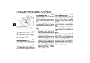 18
18 19
19 20
20 21
21 22
22 23
23 24
24 25
25 26
26 27
27 28
28 29
29 30
30 31
31 32
32 33
33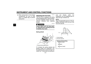 34
34 35
35 36
36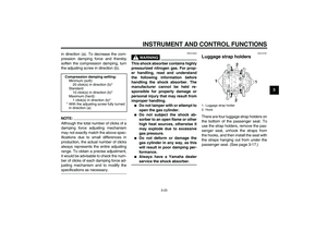 37
37 38
38 39
39 40
40 41
41 42
42 43
43 44
44 45
45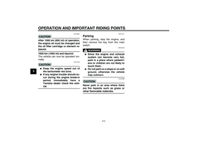 46
46 47
47 48
48 49
49 50
50 51
51 52
52 53
53 54
54 55
55 56
56 57
57 58
58 59
59 60
60 61
61 62
62 63
63 64
64 65
65 66
66 67
67 68
68 69
69 70
70 71
71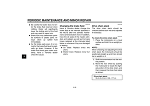 72
72 73
73 74
74 75
75 76
76 77
77 78
78 79
79 80
80 81
81 82
82 83
83 84
84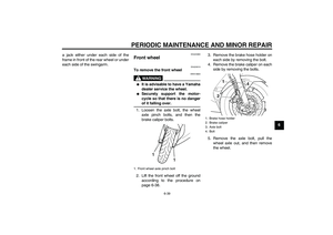 85
85 86
86 87
87 88
88 89
89 90
90 91
91 92
92 93
93 94
94 95
95 96
96 97
97 98
98 99
99 100
100 101
101 102
102 103
103