Page 25 of 104

INSTRUMENT AND CONTROL FUNCTIONS
3-11
3 4. Push the “RESET” button to select
the desired display brightness lev-
el.
5. Push the “SELECT” button to con-
firm the selected display bright-
ness level. The control mode
changes to the shift timing indica-
tor light activity function.
To set the shift timing indicator light ac-
tivity function1. Push the “RESET” button to select
one of the following indicator light
activity settings:
�
The indicator light will stay on
when activated. (This setting
is selected when the indicator
light stays on.)
�
The indicator light will flash
when activated. (This setting
is selected when the indicator
light flashes four times per
second.)
�
The indicator light is deacti-
vated; in other words, it will
not come on or flash. (This
setting is selected when the
indicator light flashes once
every two seconds.)2. Push the “SELECT” button to con-
firm the selected indicator light ac-
tivity. The control mode changes to
the shift timing indicator light acti-
vation function.
To set the shift timing indicator light ac-
tivation functionNOTE:The shift timing indicator light activation
function can be set between 10000
r/min and 16000 r/min. From 10000
r/min to 12000 r/min, the indicator light
can be set in increments of 500 r/min.
From 12000 r/min to 16000 r/min, the
indicator light can be set in incrementsof 200 r/min.
1. Push the “RESET” button to select
the desired engine speed for acti-
vating the indicator light.
2. Push the “SELECT” button to con-
firm the selected engine speed.
The control mode changes to the
shift timing indicator light deactiva-
tion function.To set the shift timing indicator light de-
activation functionNOTE:�
The indicator light deactivation
function can be set between
10000 r/min and 16000 r/min.
From 10000 r/min to 12000 r/min,
the indicator light can be set in in-
crements of 500 r/min. From
12000 r/min to 16000 r/min, the in-
dicator light can be set in incre-
ments of 200 r/min.
�
Be sure to set the deactivation
function to a higher engine speed
than for the activation function,
otherwise the shift timing indicatorlight will remain deactivated.
1. Push the “RESET” button to select
the desired engine speed for deac-
tivating the indicator light.
2. Push the “SELECT” button to con-
firm the selected engine speed.
The control mode changes to the
shift timing indicator light bright-
ness function.
5SLE1.book Page 11 Friday, August 1, 2003 4:09 PM
Page 26 of 104
INSTRUMENT AND CONTROL FUNCTIONS
3-12
3To adjust the shift timing indicator light
brightness1. Push the “RESET” button to select
the desired indicator light bright-
ness level.
2. Push the “SELECT” button to con-
firm the selected indicator light
brightness level. The multi-func-
tion display will return to the odom-
eter, tripmeter or clock mode.
EAU12330
Anti-theft alarm (optional) This model can be equipped with an
optional anti-theft alarm by a Yamaha
dealer. Contact a Yamaha dealer for
more information.
EAU12342
Handlebar switches Left1. Pass switch “”
2. Dimmer switch “/”
3. Turn signal switch “/”
4. Horn switch “”
5. Hazard switch “”
5SLE1.book Page 12 Friday, August 1, 2003 4:09 PM
Page 27 of 104

INSTRUMENT AND CONTROL FUNCTIONS
3-13
3 Right
EAU12350
Pass switch “”
Press this switch to flash the headlight.
EAU12400
Dimmer switch “/”
Set this switch to “” for the high
beam and to “” for the low beam.
EAU12460
Turn signal switch “/”
To signal a right-hand turn, push this
switch to “”. To signal a left-hand
turn, push this switch to “”. When re-
leased, the switch returns to the centerposition. To cancel the turn signal
lights, push the switch in after it has re-
turned to the center position.
EAU12500
Horn switch “”
Press this switch to sound the horn.
EAU12660
Engine stop switch “/”
Set this switch to “” before starting
the engine. Set this switch to “” to
stop the engine in case of an emergen-
cy, such as when the vehicle overturns
or when the throttle cable is stuck.
EAU12710
Start switch “”
Push this switch to crank the engine
with the starter.CAUTION:
ECA10050
See page 5-1 for starting instruc-tions prior to starting the engine.
EAU12730
Hazard switch “”
With the key in the “ON” or “” posi-
tion, use this switch to turn on the haz-
ard light (simultaneous flashing of all
turn signal lights).
The hazard light is used in case of an
emergency or to warn other drivers
when your vehicle is stopped where it
might be a traffic hazard.CAUTION:
ECA10060
Do not use the hazard light for an ex-
tended length of time, otherwise thebattery may discharge.
1. Engine stop switch “/”
2. Start switch “”
5SLE1.book Page 13 Friday, August 1, 2003 4:09 PM
Page 28 of 104

INSTRUMENT AND CONTROL FUNCTIONS
3-14
3
EAU12820
Clutch lever The clutch lever is located at the left
handlebar grip. To disengage the
clutch, pull the lever toward the handle-
bar grip. To engage the clutch, release
the lever. The lever should be pulled
rapidly and released slowly for smooth
clutch operation.
The clutch lever is equipped with a
clutch switch, which is part of the igni-
tion circuit cut-off system. (See page
3-24.)
EAU12870
Shift pedal The shift pedal is located on the left
side of the engine and is used in com-
bination with the clutch lever when
shifting the gears of the 6-speed con-
stant-mesh transmission equipped on
this motorcycle.
EAU12930
Brake lever The brake lever is located at the right
handlebar grip. To apply the front
brake, pull the lever toward the handle-
bar grip.
The brake lever is equipped with a po-
sition adjusting dial. To adjust the dis-
tance between the brake lever and the
handlebar grip, turn the adjusting dial
while holding the lever pushed away
from the handlebar grip. Make sure that
the appropriate setting on the adjusting
dial is aligned with the arrow mark on
the brake lever.
1. Clutch lever
1. Shift pedal
1. Brake lever
2. Arrow mark
3. Brake lever position adjusting dial
4. Distance between brake lever and handlebar
grip
5SLE1.book Page 14 Friday, August 1, 2003 4:09 PM
Page 29 of 104
INSTRUMENT AND CONTROL FUNCTIONS
3-15
3
EAU12941
Brake pedal The brake pedal is on the right side of
the motorcycle. To apply the rear
brake, press down on the brake pedal.
EAU13070
Fuel tank cap To open the fuel tank cap
Open the fuel tank cap lock cover, in-
sert the key into the lock, and then turn
it 1/4 turn clockwise. The lock will be re-
leased and the fuel tank cap can be
opened.
To close the fuel tank cap
1. Push the fuel tank cap into position
with the key inserted in the lock.
2. Turn the key counterclockwise to
the original position, remove it, and
then close the lock cover.
NOTE:The fuel tank cap cannot be closed un-
less the key is in the lock. In addition,
the key cannot be removed if the cap isnot properly closed and locked.
WARNING
EWA11090
Make sure that the fuel tank cap isproperly closed before riding.
1. Brake pedal
1. Fuel tank cap lock cover
2. Unlock.
5SLE1.book Page 15 Friday, August 1, 2003 4:09 PM
Page 30 of 104

INSTRUMENT AND CONTROL FUNCTIONS
3-16
3
EAU13210
Fuel Make sure that there is sufficient fuel in
the tank. Fill the fuel tank to the bottom
of the filler tube as shown.
WARNING
EWA10880
�
Do not overfill the fuel tank, oth-
erwise it may overflow when the
fuel warms up and expands.
�
Avoid spilling fuel on the hot en-gine.
CAUTION:
ECA10070
Immediately wipe off spilled fuel
with a clean, dry, soft cloth, since
fuel may deteriorate painted surfac-es or plastic parts.
EAU13390
CAUTION:
ECA11400
Use only unleaded gasoline. The use
of leaded gasoline will cause severe
damage to internal engine parts,
such as the valves and piston rings,as well as to the exhaust system.
Your Yamaha engine has been de-
signed to use premium unleaded gaso-
line with a research octane number of
95 or higher. If knocking (or pinging) oc-curs, use a gasoline of a different
brand. Use of unleaded fuel will extend
spark plug life and reduce maintenance
costs.
1. Fuel tank filler tube
2. Fuel level
Recommended fuel:
PREMIUM UNLEADED GASOLINE
ONLY
Fuel tank capacity:
17.0 L (4.49 US gal) (3.74 Imp.gal)
Fuel reserve amount (when the fuel
level warning light comes on):
3.5 L (0.92 US gal) (0.77 Imp.gal)
5SLE1.book Page 16 Friday, August 1, 2003 4:09 PM
Page 31 of 104

INSTRUMENT AND CONTROL FUNCTIONS
3-17
3
EAU13410
Fuel tank breather hose Before operating the motorcycle:�
Check the fuel tank breather hose
connection.
�
Check the fuel tank breather hose
for cracks or damage, and replace
it if damaged.
�
Make sure that the end of the fuel
tank breather hose is not blocked,
and clean it if necessary.
EAU13430
Catalytic converter This model is equipped with a catalytic
converter in the exhaust chamber.
WARNING
EWA10860
The exhaust system is hot after op-
eration. Make sure that the exhaust
system has cooled down before do-ing any maintenance work.CAUTION:
ECA10700
The following precautions must be
observed to prevent a fire hazard or
other damages.�
Use only unleaded gasoline.
The use of leaded gasoline will
cause unrepairable damage to
the catalytic converter.
�
Never park the vehicle near pos-
sible fire hazards such as grass
or other materials that easily
burn.
�
Do not allow the engine to idletoo long.
EAU14091
Seats Rider seat
To remove the rider seatPull back the rear of the rider seat as
shown, remove the bolts, and then pull
the seat off.
To install the rider seatInsert the projection on the front of the
rider seat into the seat holder as
shown, place the seat in the original po-
sition, and then install the bolts.
1. Fuel tank breather hose
1. Bolt
5SLE1.book Page 17 Friday, August 1, 2003 4:09 PM
Page 32 of 104

INSTRUMENT AND CONTROL FUNCTIONS
3-18
3
Passenger seat
To remove the passenger seat
1. Insert the key into the seat lock,
and then turn it counterclockwise.2. While holding the key in that posi-
tion, lift the front of the passenger
seat and pull it forward.
To install the passenger seat
1. Insert the projection on the rear of
the passenger seat into the seat
holder as shown, and then push
the front of the seat down to lock it
in place.
2. Remove the key.NOTE:Make sure that the seats are properlysecured before riding.
EAU14380
Helmet holders The helmet holders are located on the
bottom of the passenger seat.
To secure a helmet to a helmet hold-
er
1. Remove the passenger seat. (See
page 3-17.)
2. Attach the helmet to a helmet hold-
er, and then securely install the
passenger seat.
WARNING
EWA11040
Never ride with a helmet attached to
a helmet holder, since the helmet
may hit objects, causing loss of con-trol and possibly an accident.
1. Projection
2. Seat holder
1. Passenger seat lock
2. Unlock.
1. Projection
2. Seat holder
1. Helmet holder
5SLE1.book Page 18 Friday, August 1, 2003 4:09 PM
 1
1 2
2 3
3 4
4 5
5 6
6 7
7 8
8 9
9 10
10 11
11 12
12 13
13 14
14 15
15 16
16 17
17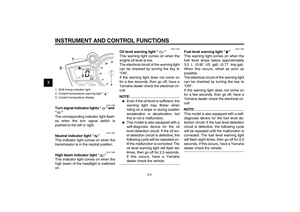 18
18 19
19 20
20 21
21 22
22 23
23 24
24 25
25 26
26 27
27 28
28 29
29 30
30 31
31 32
32 33
33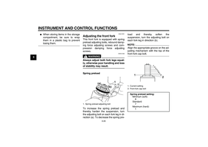 34
34 35
35 36
36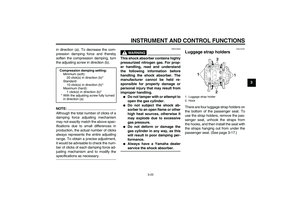 37
37 38
38 39
39 40
40 41
41 42
42 43
43 44
44 45
45 46
46 47
47 48
48 49
49 50
50 51
51 52
52 53
53 54
54 55
55 56
56 57
57 58
58 59
59 60
60 61
61 62
62 63
63 64
64 65
65 66
66 67
67 68
68 69
69 70
70 71
71 72
72 73
73 74
74 75
75 76
76 77
77 78
78 79
79 80
80 81
81 82
82 83
83 84
84 85
85 86
86 87
87 88
88 89
89 90
90 91
91 92
92 93
93 94
94 95
95 96
96 97
97 98
98 99
99 100
100 101
101 102
102 103
103
