Page 29 of 457
2-1
GENERAL SPECIFICATIONSSPEC
SPECIFICATIONS
GENERAL SPECIFICATIONS
ItemStandardLimit
Model code5VY4 (USA), 5VY5 (CAL)���
Dimensions
Overall length
Overall width
Overall height
Seat height
Wheelbase
Minimum ground clearance
Minimum turning radius
2,065 mm (8.13 in)
720 mm (28.3 in)
1,105 mm (43.5 in)
835 mm (32.9 in)
1,395 mm (54.9 in)
135 mm (5.31 in)
3,400 mm (133.9 in)���
���
���
���
���
���
���
Weight
Wet (with oil and a full fuel tank)
Maximum load (except motorcycle)
193 kg (425 lb) (USA)
194 kg (428 lb) (CAL)
202 kg (445 lb) (USA)
201 kg (443 lb) (CAL)���
���
ProCarManuals.com
Page 63 of 457
2-35
CABLE ROUTINGSPEC
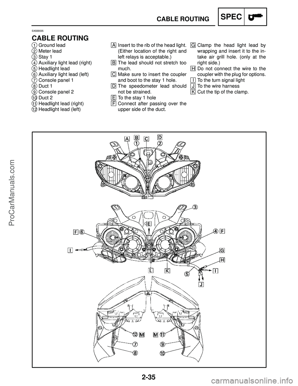
G Clamp the head light lead by
wrapping and insert it to the in-
take air grill hole. (only at the
right side.)
H Do not connect the wire to the
coupler with the plug for options.
I To the turn signal light
J To the wire harness
K Cut the tip of the clamp.A Insert to the rib of the head light.
(Either location of the right and
left relays is acceptable.)
B The lead should not stretch too
much.
C Make sure to insert the coupler
and boot to the stay 1 hole.
D The speedometer lead should
not be strained.
E To the stay 1 hole
F Connect after passing over the
upper side of the duct.1Ground lead
2Meter lead
3Stay 1
4Auxiliary light lead (right)
5Headlight lead
6Auxiliary light lead (left)
7Console panel 1
8Duct 1
9Console panel 2
10Duct 2
11Headlight lead (right)
12Headlight lead (left)
EAS00035
CABLE ROUTING
ProCarManuals.com
Page 71 of 457

2-43
33Throttle body side cap
34Mud guard
35Turn signal light lead
36License plate light lead
37Rear fender rib
38Speed sensor lead
39Rear brake light switch lead
40Rear frame
41Swingarm bracket
42Main fuse lead
43Starting circuit cut-off relay lead
44Turn signal light relay lead
45Starter relay lead
46Main fuse lead (To the battery
positive lead)
47Right handlebar switch lead
17Battery negative lead
18Starter motor lead
19A.C.magneto lead
20Oil level switch lead
21Sidestand switch lead
22Throttle body lead
23Coolant reservoir tank drain hose
24Fuel tank drain hose
25Cover 7
26Radiator fan motor lead (left)
27Radiator fan motor lead (right)
28Wire harness
29Pipe 3
30Frame
31Coolant reservoir tank hose
32Thermo stat assembly breather
hose
CABLE ROUTINGSPEC
1Heat protector
2Crankshaft position sensor lead
3Neutral switch lead
4Ground lead
5Coolant reservoir tank
6Battery positive lead
7Starter relay
8Turn signal relay
9Main fuse
10Lean angle cut-off switch
11Atmospheric pressure sensor
12Tail / brake light lead
13Rear fender
14Seat lock cable
15Anti safety alarm coupler
16Starting circuit cut-off relay
ProCarManuals.com
Page 72 of 457

2-44
K Pass the water hose lower side
of the thermostat, and between
the ground lead and the neutral
switch.
L Install the leads so that the en-
gine ground lead is positioned
lower and the battery negative
lead to be upper. Install the pro-
trusion of each lead to be above
the vehicle.
M Route the crankshaft position
sensor lead under the wire har-
ness.
N To the fuel pump
O Clamp the wire harness winding
in and insert it to the frame hole.A Pass the wire harness through
the clamp inserted to the radiator
stay.
B To the headlight lead
C Clamp the lead between three
protrusions of the pipe (the first
and second parts from the ve-
hicle front). Point the tip of the
clamp (excessive part) to the in-
side of the vehicle.
D To the vehicle right side diagram
E To the engine
F Clamp the lead between three
protrusions of the pipe (the in-
side and outside of the vehicle).G Point the tip of the clamp (exces-
sive part) to the inside of the ve-
hicle.
H All hoses and leads should be
routed over the vehicle’s upper
side above the heat protector.
I To the starter motor
J Fasten the wire harness, clank
shaft position sensor lead, rear
brake light switch lead and
speed sensor lead with a clamp.
Then, point the tip of the clamp
(cut the tip of the clamp leaving 2
to 4 mm (0.08 to 0.16 in).) to the
inside of the vehicle.
CABLE ROUTINGSPEC
ProCarManuals.com
Page 102 of 457
3-25
MEASURING THE COMPRESSION PRESSURE
CHK
ADJ
WARNING
NOTE: 4. Install:
�compression gauge
1
�adapter
Compression gauge
90890-03081, YU-33223
Adapter
90890-04136
5. Measure:
�compression pressure
Out of specification � Refer to steps (c) and
(d).
Compression pressure
(at sea level)
Minimum
1,290 kPa (12.90 kg / cm
2,
12.90 bar, 183.48 psi)
Standard
1,480 kPa (14.80 kg / cm
2,
14.80 bar, 210.5 psi)
Maximum
1,660 kPa (16.60 kg / cm
2,
16.60 bar, 236.11 psi)
a. Turn the main switch to “ON”.
b. With the throttle wide open, crank the engine
until the reading on the compression gauge
stabilizes.
To prevent sparking, ground all spark plug
leads before cranking the engine.
The difference in compression pressure be-
tween cylinders should not exceed 100 kPa (1
kg/cm
2, 1 bar, 14.22 psi).
c. If the compression pressure is above the
maximum specification, check the cylinder
head, valve surfaces and piston crown for
carbon deposits.
Carbon deposits � Eliminate.
ProCarManuals.com
Page 153 of 457

4-6
FRONT WHEEL AND BRAKE DISCSCHAS
NOTE:
91 Nm (9.1 m�kg, 66 ft�lb)
20 Nm (2.0 m�kg, 14 ft�lb)
CAUTION:
Brake disc bolt
Front : 18 Nm (1.8 m�kg, 13 ft�lb)
Rear : 30 Nm (3.0 m�kg, 22 ft�lb)
LOCTITE
d. Measure the brake disc deflection.
e. If out of specification, repeat the adjustment
steps until the brake disc deflection is within
specification.
f. If the brake disc deflection cannot be brought
within specification, replace the brake disc.
EAS00545
INSTALLING THE FRONT WHEEL
The following procedure applies to both brake
discs.
1. Lubricate:
�wheel axle
�oil seal lips
Recommended lubricant
Lithium-soap-based grease
2. Lift the wheel up between the fork legs.
3. Insert the wheel axle.
Install the tire and wheel with the mark
1 point-
ing in the direction of wheel rotation.
4. Lower the front wheel so that it is on the
ground.
5. Tighten:
�wheel axle
�wheel axle pinch bolt
Before tightening the wheel axle nut, push
down hard on the handlebars several times
and check if the front fork rebounds smooth-
ly.
ProCarManuals.com
Page 228 of 457
5-6
Order Job / Part Q’ty Remarks
3
4
5
6
7
8
9
10Clutch cable
Ground lead
Stator coil assembly coupler
Crankshaft position sensor lead coupler
Oil level switch connector
Neutral switch connector
Speed sensor coupler
Cylinder identification sensor coupler1
2
1
1
1
1
1
1First, disconnect the negative battery
lead, and then the positive battery lead.
For connecting, reverse the disconnec-
tion procedure.
Disconnect.
Disconnect.
Disconnect.
Disconnect.
Disconnect.
Disconnect.
For installation, reverse the removal
procedure.
CAUTION:
ENGINEENG
ProCarManuals.com
Page 363 of 457

7-19
FUEL INJECTION SYSTEMFI
Fault code No.15SymptomThrottle position sensor – open or shrt circuit detected.
Used diagnostic code No. 01 (throttle position sensor)
OrderInspection operation item and probable
causeOperation item and countermeasureReinstatement
method
1Installed condition of throttle position
sensor.Check the installed area for looseness or
pinching.
Check that it is installed in the specified
position.
Refer to “THROTTLE BODIES” section.Reinstated by
turning the
main switch
ON.
2Connected condition of connector
Inspect the coupler for any pins that
may have pulled out.
Check the locking condition of the
coupler.If there is a malfunction, repair it and connect it
securely.
Throttle position sensor coupler
Main wiring harness ECU coupler
Sub-wire harness coupler
3Open or short circuit in wiring harness
and / or sub lead.Repair or replace if there is an open or short
circuit.
Between sensor coupler and ECU coupler
Black / Blue – Black / Blue
Yellow – Yellow
Blue – Blue
4Throttle position sensor lead wire open
circuit output voltage check.Check for open circuit and replace the throttle
position sensor.
Black / Blue – Yellow
Open circuit item Output voltage
Ground wire open 5 V
circuit
Output wire open 0V
circuit
Power supply wire 0V
open circuit
5Defective throttle position sensor.Execute the diagnostic mode (Code No.01).
Replace if defective.
Refer to “THROTTLE BODIES” section.
Fault code No.16SymptomStuck throttle position sensor detected.
Used diagnostic code No.01 (throttle position sensor)
OrderInspection operation item and probable
causeOperation item and countermeasureReinstatement
method
1When detecting fault code No.15.Refer to “Fault code No.15”.Reinstated by
2Installed condition of throttle position
sensor.Check the installed area for looseness or pinching.
Check that it is installed in the specified position.
Refer to “THROTTLE BODIES” section.starting the
engine,
operating it at
idle and then3Defective throttle position sensorExecute the diagnostic mode (Code No.01).
Replace if defective.
Refer to “THROTTLE BODIES” section.idle, and then
racing it.
ProCarManuals.com