Page 426 of 754
4 - 63
ENGBALANCER
REMOVAL POINTS
Balancer drive gear and balancer driven
gear
1. Straighten the lock washer tab.
2. Loosen:
�Nut (primary drive gear) 1
�Nut (balancer) 2
NOTE:
Place an aluminum plate a between the teeth
of the balancer drive gear 3 and driven gear
4.
Balancer
1. Remove:
�Balancer 1
NOTE:
When removing the balancer shaft, align the
center of the balancer shaft weight a along
the line connecting the centers of the crank-
shaft and balancer shaft.
INSPECTION
Primary drive gear, balancer drive gear and
balancer driven gear
1. Inspect:
�Primary drive gear 1
�Balancer drive gear 2
�Balancer driven gear 3
Wear/damage → Replace.
Balancer
1. Inspect:
�Balancer
Cracks/damage → Replace.
Page 427 of 754
 ENG
4 - 63
BALANCIER
AUSGLEICHSWELLE
COMPENSADOR
AUSBAU
Ausgleichswellen-Antriebs- und -
Abtriebsräder
1. Die Lasche der Sicherungs-
scheibe umbiegen.
2. Lockern:
�Mutter (Primärantriebsrad) 1
�Mut")
ENG
4 - 63
BALANCIER
AUSGLEICHSWELLE
COMPENSADOR
AUSBAU
Ausgleichswellen-Antriebs- und -
Abtriebsräder
1. Die Lasche der Sicherungs-
scheibe umbiegen.
2. Lockern:
�Mutter (Primärantriebsrad) 1
�Mutter (Ausgleichswelle) 2
HINWEIS:
Ein Stückchen Aluminium a zwi-
schen die Zähne des Ausgleichswel-
len-Antriebsrades 3 und Aus-
gleichswellen-Abtriebrades 4 legen.
Ausgleichswelle
1. Demontieren:
�Ausgleichswelle 1
HINWEIS:
Beim Ausbau der Ausgleichswelle
muß sich das Ausgleichsgewicht mit-
tig a auf der Fluchtlinie zwischen
den Mittelpunkten der Nockenwellen-
und Ausgleichswellen-Enden befin-
den.
PRÜFUNG
Primär- und Ausgleichswellen-
Antriebs- und -Abtriebsräder
1. Kontrollieren:
�Primärantriebsrad 1
�Ausgleichswellen-Antriebs-
rad 2
�Ausgleichswellen-Abtriebs-
rad 3
Verschleiß/Beschädigung →
Erneuern.
Ausgleichswelle
1. Kontrollieren:
�Ausgleichswelle
Rißbildung/Beschädigung
→ Erneuern. POINTS DE DEPOSE
Pignon menant et pignon mené du
balancier
1. Redresser l’ongle de rondelle
d’arrêt.
2. Desserrer:
�Ecrou (pignon menant pri-
maire) 1
�Ecrou (balancier) 2
N.B.:
Placer une plaque en aluminium a entre
les dents du pignon menant 3 et le
pignon mené 4 du balancier.
Balancier
1. Déposer:
�Balancier 1
N.B.:
Avant de déposer l’arbre de balancier,
aligner le centre du poids de l’arbre de
balancier a avec l’axe reliant le centre
du vilebrequin et le centre de l’arbre de
balancier.
CONTROLE
Pignon menant primaire, pignon
menant et pignon mené du balancier
1. Contrôler:
�Pignon menant primaire 1
�Pignon menant du balancier 2
�Pignon mené du balancier 3
Usure/endommagements →
Remplacer.
Balancier
1. Contrôler:
�Balancier
Craquelures/endommagement
→ Remplacer.PUNTOS DE EXTRACCIÓN
Engranaje de accionamiento del com-
pensador y engranaje impulsor del
compensador
1. Enderece la lengüeta de la aran-
dela de freno.
2. Aflojar:
�Tuerca (engranaje de acciona-
miento primario) 1
�Tuerca (compensador) 2
NOTA:
Coloque una plancha de aluminio a
entre el diente del engranaje de acciona-
miento del compensador 3 y el engra-
naje impulsor 4.
Compensador
1. Extraer:
�Compensador 1
NOTA:
Cuando extraiga el eje del compensador,
alinee el centro del peso del eje del com-
pensador a a través de la línea conec-
tando los centros del cigüeñal y el eje del
compensador.
INSPECCIÓN
Engranaje de accionamiento prima-
rio, engranaje de accionamiento del
compensador y engranaje impulsor
del compensador
1. Inspeccionar:
�Engranaje de accionamiento
primario 1
�Engranaje de accionamiento
del compensador 2
�Engranaje de accionamiento
del compensador 3
Desgaste/daños → Reemplazar.
Compensador
1. Inspeccionar:
�Compensador
Grietas/daños → Reemplazar.
Page 428 of 754
 4 - 64
ENGBALANCER
ASSEMBLY AND INSTALLATION
Balancer, balancer drive gear and balancer
driven gear
1. Install:
�Balancer 1
NOTE:
When installing the balancer shaft, align the
center of the balancer")
4 - 64
ENGBALANCER
ASSEMBLY AND INSTALLATION
Balancer, balancer drive gear and balancer
driven gear
1. Install:
�Balancer 1
NOTE:
When installing the balancer shaft, align the
center of the balancer shaft weight a along
the line connecting the centers of the crank-
shaft and balancer shaft.
2. Install:
�Balancer driven gear 1
NOTE:
Install the balancer driven gear onto the bal-
ancer while aligning the punch mark a on the
balancer driven gear with the lower spline b
on the balancer end.
3. Install:
�Balancer drive gear 1
NOTE:
�Align the punched mark a on the balancer
drive gear with the punched mark b on the
balancer driven gear.
�Align the punched mark c on the balancer
drive gear with the lower spline d on the
crankshaft.
4. Install:
�Lock washer 1
�Nut (balancer) 2
�Primary drive gear 3
�Nut (primary drive gear) 4
NOTE:
�Apply the molybdenum disulfide grease on
the contact surface of the nut (primary drive
gear).
�Install the primary drive gear with its stepped
side b facing the engine.
�Place an aluminum plate a between the
teeth of the balancer drive gear 5 and
driven gear 6.
5. Bend the lock washer tab.
T R..50 Nm (5.0 m · kg, 36 ft · lb)
T R..85 Nm (8.5 m · kg, 61 ft · lb)
Page 442 of 754
4 - 71
ENGKICK AXLE AND SHIFT SHAFT
REMOVAL POINTS
EC4B3101
Kick axle assembly
1. Remove:
�Kick axle assembly 1
NOTE:
Unhook the torsion spring 2 from the hole a
in the crankcase.
EC4C3101
Shift guide and shift lever assembly
1. Remove:
�Bolt (shift guide)
�Shift guide 1
�Shift lever assembly 2
NOTE:
The shift lever assembly is disassembled at
the same time as the shift guide.
EC4N3100
Segment
1. Remove:
�Bolt (segment) 1
�Segment 2
NOTE:
Turn the segment counterclockwise until it
stops and loosen the bolt.
INSPECTION
EC4C4200
Kick axle and ratchet wheel
1. Check:
�Ratchet wheel 1 smooth movement
Unsmooth movement → Replace.
�Kick axle 2
Wear/damage → Replace.
�Spring 3
Broken → Replace.
EC4C4300
Kick gear, kick idle gear and ratchet wheel
1. Inspect:
�Kick gear 1
�Kick idle gear 2
�Ratchet wheel 3
�Gear teeth a
�Ratchet teeth b
Wear/damage → Replace.
Page 450 of 754
4 - 75
ENGKICK AXLE AND SHIFT SHAFT
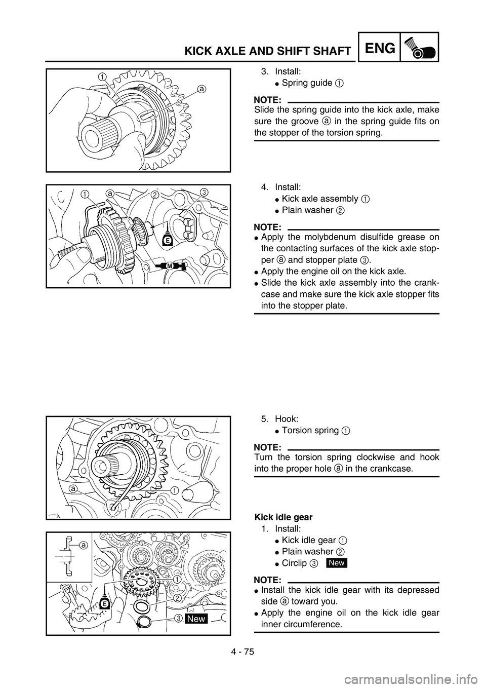
3. Install:
�Spring guide 1
NOTE:
Slide the spring guide into the kick axle, make
sure the groove a in the spring guide fits on
the stopper of the torsion spring.
4. Install:
�Kick axle assembly 1
�Plain washer 2
NOTE:
�Apply the molybdenum disulfide grease on
the contacting surfaces of the kick axle stop-
per a and stopper plate 3.
�Apply the engine oil on the kick axle.
�Slide the kick axle assembly into the crank-
case and make sure the kick axle stopper fits
into the stopper plate.
5. Hook:
�Torsion spring 1
NOTE:
Turn the torsion spring clockwise and hook
into the proper hole a in the crankcase.
Kick idle gear
1. Install:
�Kick idle gear 1
�Plain washer 2
�Circlip 3
NOTE:
�Install the kick idle gear with its depressed
side a toward you.
�Apply the engine oil on the kick idle gear
inner circumference.
New
Page 458 of 754
 4 - 79
ENGAC MAGNETO AND STARTER CLUTCH
Starter clutch
1. Check:
�Starter clutch
Damage/wear → Replace.
2. Check:
�Idle gear
�Idle gear shaft
�Starter clutch gear
Pitting/burrs/chips/roughness/wear")
4 - 79
ENGAC MAGNETO AND STARTER CLUTCH
Starter clutch
1. Check:
�Starter clutch
Damage/wear → Replace.
2. Check:
�Idle gear
�Idle gear shaft
�Starter clutch gear
Pitting/burrs/chips/roughness/wear →
Replace the defective parts.
3. Check:
�Starter clutch operation
�Install the starter clutch drive gear 1 onto
the starter clutch 2 and hold the starter
clutch.
�When turning the starter clutch drive gear
counterclockwise ı, the starter clutch and
the starter clutch drive gear should
engage. If the starter clutch drive gear and
starter clutch do not engage, the starter
clutch is faulty and must be replaced.
�When turning the starter clutch drive gear
clockwise Å, it should turn freely.
If the starter clutch drive gear does not
turn freely, the starter clutch is faulty and
must be replaced.
Torque limiter
1. Check:
�Torque limiter
Damage/wear → Replace.
EC4L5000
ASSEMBLY AND INSTALLATION
AC magneto and starter clutch
1. Install:
�Stator 1
�Bolt (stator) 2
�Pick-up coil 3
�Bolt (pick-up coil) 4
NOTE:
Pass the AC magneto lead 5 under the pick-
up coil.
T R..7 Nm (0.7 m · kg, 5.1 ft · lb)
T R..10 Nm (1.0 m · kg, 7.2 ft · lb)
Page 468 of 754
4 - 84
ENGENGINE REMOVAL
Extent of removal:1 Engine removal
Extent of removal Order Part name Q’ty Remarks
Crankcase cover (left) Refer to “AC MAGNETO AND
STARTER CLUTCH” section for remov-
ing the starter motor lead.
Disconnect the starter motor
lead.Refer to “ELECTRIC STARTING SYS-
TEM” section in the CHAPTER 6.
Negative battery lead Disconnect at the starter motor side.
1 Engine skid plate (front) 1
2 Neutral switch 1
3 Oil hose 2
4 Chain cover 1
5 Nut (drive sprocket) 1
Refer to “REMOVAL POINTS”. 6 Lock washer 1
7 Drive sprocket 1
8 Clip 1
9 Bolt (brake pedal) 1
10 Brake pedal 1
1
Page 472 of 754
4 - 86
ENGENGINE REMOVAL
EC4M3000
REMOVAL POINTS
EC4F3100
Drive sprocket
1. Remove:
�Nut (drive sprocket) 1
�Lock washer 2
NOTE:
�Straighten the lock washer tab.
�Loosen the nut while applying the rear brake.
2. Remove:
�Drive sprocket 1
�Drive chain 2
NOTE:
Remove the drive sprocket together with the
drive chain.
EC4M3301
Engine removal
1. Remove:
�Pivot shaft 1
NOTE:
If the pivot shaft is pulled all the way out, the
swingarm will come loose. If possible, insert a
shaft of similar diameter into the other side of
the swingarm to support it.
2. Remove:
�Engine 1
From right side.
NOTE:
Make sure that the couplers, hoses and cables
are disconnected.
1


 4 - 84
ENGENGINE REMOVAL
Extent of removal:1 Engine removal
Extent of removal Order Part name Q’ty Remarks
Crankcase cover (left) Refer to “AC MAGNETO AND
STARTER CLUTCH” section for remov-
ing")
