Page 26 of 754
GEN
INFO
1 - 1
DESCRIPTION
EC100000
GENERAL INFORMATION
EC110000
DESCRIPTION
1
Clutch lever
2
Hot starter lever
3
“ENGINE STOP” button
4
Trip meter
5
Main switch
6
Start switch
7
Front brake lever
8
Throttle grip
9
Radiator cap
0
Fuel tank cap
A
Taillight
B
Kickstarter
C
Fuel tank
D
Headlight
E
Radiator
F
Coolant drain bolt
G
Rear brake pedal
H
Valve joint
I
Fuel cock
J
Cold starter knob
K
Air cleaner
L
Drive chain
M
Shift pedal
N
Oil dipstick
O
Front fork
NOTE:
�
The machine you have purchased may differ
slightly from those shown in the following.
�
Designs and specifications are subject to
change without notice.
A
BCD
E
F G
1234
5
6
7
8
9 0
HI
J
K
L M
N O
Page 86 of 754
 SPEC
2 - 11
MAINTENANCE SPECIFICATIONS
Part to be tightened Thread size Q’tyTightening torque
Nm m·kg ft·lb
Spark plug M10S
×
1.0 1 13 1.3 9.4
Camshaft cap M6
×
1.0 10 10 1.0 7.2
Cyl")
SPEC
2 - 11
MAINTENANCE SPECIFICATIONS
Part to be tightened Thread size Q’tyTightening torque
Nm m·kg ft·lb
Spark plug M10S
×
1.0 1 13 1.3 9.4
Camshaft cap M6
×
1.0 10 10 1.0 7.2
Cylinder head blind plug screw M12
×
1.0 1 28 2.8 20
Cylinder head (stud bolt) M6
×
1.0 2 7 0.7 5.1
M8
×
1.25 1 15 1.5 11
(bolt) M10
×
1.25 4 Refer to NOTE.*
1
(nut) M6
×
1.0 2 10 1.0 7.2
Cylinder head cover M6
×
1.0 2 10 1.0 7.2
Cylinder M6
×
1.0 1 10 1.0 7.2
Timing chain tensioner M6
×
1.0 2 10 1.0 7.2
Tensioner cap bolt M6
×
1.0 1 7 0.7 5.1
Timing chain guide (rear) M6
×
1.0 2 10 1.0 7.2
Exhaust pipe (nut) M8
×
1.25 1 13 1.3 9.4
(bolt) M8
×
1.25 1 24 2.4 17
Silencer M8
×
1.25 2 35 3.5 25
Silencer clamp M8
×
1.25 1 16 1.6 11
Exhaust pipe protector M6
×
1.0 3 10 1.0 7.2
Spark arrester (for USA) M6
×
1.0 3 10 1.0 7.2
Silencer end pipe (for USA) M6
×
1.0 1 10 1.0 7.2
Carburetor joint clamp (cylinder head side) M5
×
0.8 1 3 0.3 2.2
Carburetor joint clamp (carburetor side) M4
×
0.7 1 3 0.3 2.2
Air filter case M6
×
1.0 2 8 0.8 5.8
Air filter joint clamp M6
×
1.0 1 3 0.3 2.2
Air filter joint and air filter case M5
×
0.8 1 4 0.4 2.9
Throttle cable (pull) M6
×
1.0 1 4 0.4 2.9
Throttle cable (return) M12
×
1.0 1 11 1.1 8.0
Throttle cable cover M5
×
0.8 2 4 0.4 2.9
Hot starter plunger M12
×
1.0 1 2 0.2 1.4
Radiator panel (upper) M6
×
1.0 2 10 1.0 7.2
Radiator M6
×
1.0 6 10 1.0 7.2
Radiator hose clamp M6
×
1.0 8 2 0.2 1.4
Radiator pipe 1, 2 M10
×
1.0 2 10 1.0 7.2
Impeller M8
×
1.25 1 14 1.4 10
Water pump housing cover M6
×
1.0 3 10 1.0 7.2
Coolant drain bolt M6
×
1.0 1 10 1.0 7.2
Oil pump cover M4
×
0.7 1 2 0.2 1.4
Oil pump M6 × 1.0 3 10 1.0 7.2
Engine oil drain bolt (oil filter) M6 × 1.0 1 10 1.0 7.2
Oil filter cover M6 × 1.0 2 10 1.0 7.2
Oil delivery pipe 1 M10 × 1.25 1 20 2.0 14
M8 × 1.25 2 18 1.8 13
Oil delivery pipe 2 M6 × 1.0 1 10 1.0 7.2
Oil hose M6 × 1.0 2 8 0.8 5.8
Page 87 of 754
 SPEC
2 - 12
MAINTENANCE SPECIFICATIONS
NOTE:
- marked portion shall be checked for torque tightening after break-in or before each race.
NOTE:
*1: Tighten the cylinder head bolts to 30 Nm (3.0 m · kg")
SPEC
2 - 12
MAINTENANCE SPECIFICATIONS
NOTE:
- marked portion shall be checked for torque tightening after break-in or before each race.
NOTE:
*1: Tighten the cylinder head bolts to 30 Nm (3.0 m · kg, 22 ft · lb) in the proper tightening sequence,
remove and retighten the cylinder head bolts to 20 Nm (2.0 m · kg, 14 ft · lb) in the proper tightening
sequence, and then tighten the cylinder head bolts further to reach the specified angle 180˚ in the
proper tightening sequence.Oil check bolt M6 × 1.0 1 10 1.0 7.2
Oil hose clamp–2 2 0.2 1.4
Clutch cover M6 × 1.0 7 10 1.0 7.2
Crankcase cover (right) M6 × 1.0 10 10 1.0 7.2
Crankcase cover (left) M6 × 1.0 9 10 1.0 7.2
Idle gear cover (starter motor) M6 × 1.0 2 10 1.0 7.2
Crankcase M6 × 1.0 12 12 1.2 8.7
Clutch cable holder M6 × 1.0 1 10 1.0 7.2
Oil drain bolt (crankcase rear) M10 × 1.25 1 20 2.0 14
(crankcase left) M6 × 1.0 1 10 1.0 7.2
Oil drain bolt (frame) M8 × 1.25 1 23 2.3 17
Oil strainer (frame) M14 × 1.5 1 70 7.0 50
Crankcase bearing stopper M6 × 1.0 15 10 1.0 7.2
Drive axle oil seal stopper M6 × 1.0 2 10 1.0 7.2
Ratchet wheel guide M6 × 1.0 2 12 1.2 8.7
Stopper plate M6 × 1.0 2 12 1.2 8.7
Kickstarter M8 × 1.25 1 33 3.3 24
Screw (kickstarter) M6 × 1.0 1 7 0.7 5.1
Starter clutch M6 × 1.0 6 16 1.6 11
Primary drive gear M20 × 1.0 1 85 8.5 61
Clutch boss M20 × 1.0 1 75 7.5 54
Push lever M6 × 1.0 1 10 1.0 7.2
Clutch spring M6 × 1.0 6 8 0.8 5.8
Balancer driven gear M14 × 1.0 1 50 5.0 36
Balancer weight plate M6 × 1.0 3 10 1.0 7.2
Drive sprocket M20 × 1.0 1 75 7.5 54
Drive sprocket cover M6 × 1.0 2 8 0.8 5.8
Shift pedal M6 × 1.0 1 12 1.2 8.7
Shift guide M6 × 1.0 2 10 1.0 7.2
Stopper lever M6 × 1.0 1 10 1.0 7.2
Segment M8 × 1.25 1 30 3.0 22 Part to be tightened Thread size Q’tyTightening torque
Nm m·kg ft·lb
Page 188 of 754
 3 - 5
INSP
ADJ
EC350000
ENGINE
COOLANT LEVEL INSPECTION
WARNING
Do not remove the radiator cap 1, drain
bolt and hoses when the engine and radia-
tor are hot. Scalding hot fluid and steam
may be blown")
3 - 5
INSP
ADJ
EC350000
ENGINE
COOLANT LEVEL INSPECTION
WARNING
Do not remove the radiator cap 1, drain
bolt and hoses when the engine and radia-
tor are hot. Scalding hot fluid and steam
may be blown out under pressure, which
could cause serious injury.
When the engine has cooled, place a thick
towel over the radiator cap, slowly rotate
the cap counterclockwise to the detent.
This procedure allows any residual pres-
sure to escape. When the hissing sound
has stopped, press down on the cap while
turning counterclockwise and remove it.
CAUTION:
Hard water or salt water is harmful to the
engine parts. You may use distilled water, if
you can’t get soft water.
1. Place the machine on a level place, and
hold it in an upright position.
2. Inspect:
�Coolant level
Coolant level should be between the
maximum a and minimum b marks.
Coolant level is below the “LOW” level
line → Add soft water (tap water) up to
the proper level.
3. Start the engine and let it warm up for
several minutes.
4. Turn off the engine and check the coolant
level again.
NOTE:
Before checking the coolant level, wait a few
minutes until the coolant settles.
LOWFULLCOOLANT
a
b
COOLANT REPLACEMENT
WARNING
Do not remove the radiator cap when the
engine is hot.
ENGINE/COOLANT LEVEL INSPECTION/
COOLANT REPLACEMENT
Page 190 of 754
3 - 6
INSP
ADJ
COOLANT REPLACEMENT
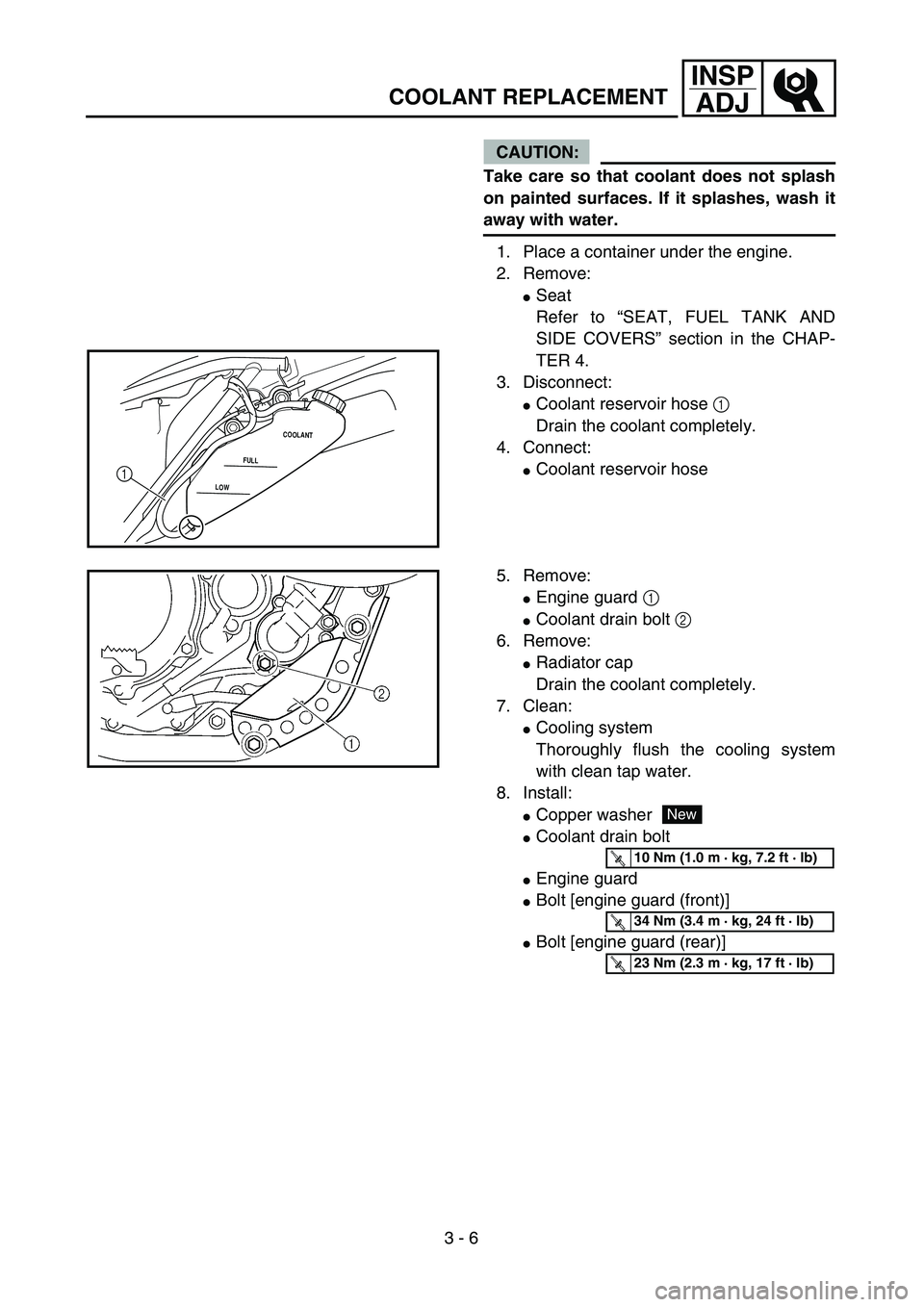
CAUTION:
Take care so that coolant does not splash
on painted surfaces. If it splashes, wash it
away with water.
1. Place a container under the engine.
2. Remove:
�Seat
Refer to “SEAT, FUEL TANK AND
SIDE COVERS” section in the CHAP-
TER 4.
3. Disconnect:
�Coolant reservoir hose 1
Drain the coolant completely.
4. Connect:
�Coolant reservoir hoseLOWFULLCOOLANT1
5. Remove:
�Engine guard 1
�Coolant drain bolt 2
6. Remove:
�Radiator cap
Drain the coolant completely.
7. Clean:
�Cooling system
Thoroughly flush the cooling system
with clean tap water.
8. Install:
�Copper washer
�Coolant drain bolt
�Engine guard
�Bolt [engine guard (front)]
�Bolt [engine guard (rear)]
New
T R..10 Nm (1.0 m · kg, 7.2 ft · lb)
T R..34 Nm (3.4 m · kg, 24 ft · lb)
T R..23 Nm (2.3 m · kg, 17 ft · lb)
Page 210 of 754
3 - 16
INSP
ADJ
ENGINE OIL REPLACEMENT
6. Idle the engine more than 10 seconds
while keeping the motorcycle upright.
Then stop the engine and add the oil to
the maximum level.
7. Install:
�Oil tank cap
ENGINE OIL REPLACEMENT
1. Start the engine and let it warm up for
several minutes.
2. Stop the engine and place an oil pan
under the drain bolt.
3. Remove:
�Oil tank plug 1
�Oil filler cap 2
�Drain bolt (with gasket) 3
�Oil filter drain bolt (O-ring) 4
�Drain bolt (with gasket) 5
�Drain bolt (with gasket) 6
Drain the crankcase and oil tank
(frame) of its oil.
4. Remove:
�Engine skid plate
�Engine oil hose clamp 1
�Bolt (engine oil hose) 2
�Engine oil hose 3
�Oil strainer (frame) 4
5. Clean:
�Oil strainer (frame)
Page 212 of 754
 3 - 17
INSP
ADJ
ENGINE OIL REPLACEMENT
6. If the oil filter is to be replaced during this
oil change, remove the following parts
and reinstall them.
7. Install:
�Plain washer 1
�Oil strainer (frame)")
3 - 17
INSP
ADJ
ENGINE OIL REPLACEMENT
6. If the oil filter is to be replaced during this
oil change, remove the following parts
and reinstall them.
7. Install:
�Plain washer 1
�Oil strainer (frame) 2
�Engine oil hose 3
�Bolt (engine oil hose) 4
�Engine oil hose clamp 5
�Engine skid plate
8. Install:
�Gaskets
�Oil filter drain bolt
�Drain bolt (crankcase rear)
�Drain bolt (crankcase left)
�Drain bolt (frame)
9. Fill:
�Crankcase Replacement steps:
�Remove the oil filter cover 1 and oil filter
element 2.
�Check the O-rings 3, if cracked or dam-
aged, replace them with a new one.
�Install the oil filter element and oil filter
cover.
T R..
Oil filter cover:
10 Nm (1.0 m • kg, 7.2 ft • lb)
Oil quantity:
Periodic oil change:
1.0 L (0.88 Imp qt, 1.06 US qt)
With oil filter replacement:
1.1 L (0.97 Imp qt, 1.16 US qt)
Total amount:
1.2 L (1.06 Imp qt, 1.27 US qt)
New
T R..70 Nm (7.0 m · kg, 50 ft · lb)
T R..8 Nm (0.8 m · kg, 5.8 ft · lb)
T R..2 Nm (0.2 m · kg, 1.4 ft · lb)
T R..10 Nm (1.0 m · kg, 7.2 ft · lb)
New
T R..10 Nm (1.0 m · kg, 7.2 ft · lb)
T R..20 Nm (2.0 m · kg, 14 ft · lb)
T R..10 Nm (1.0 m · kg, 7.2 ft · lb)
T R..23 Nm (2.3 m · kg, 17 ft · lb)
Page 238 of 754
3 - 29
INSP
ADJ
FRONT BRAKE PAD INSPECTION AND REPLACEMENT
�Loosen the pad pin 2.
�Remove the brake hose holder 3 and cal-
iper 4 from the front fork.
�Remove the pad pin and brake pads 5.
�Connect the transparent hose 6 to the
bleed screw 7 and place the suitable con-
tainer under its end.
�Loosen the bleed screw and push the cali-
per piston in.
CAUTION:
Do not reuse the drained brake fluid.
�Tighten the bleed screw.
T R..
Bleed screw:
6 Nm (0.6 m • kg, 4.3 ft • lb)
�Install the brake pads 8 and pad pin.
NOTE:
�Install the brake pads with their projections
a into the caliper recesses b.
�Temporarily tighten the pad pin at this
point.
�Install the brake hose holder 9 and cali-
per 0 and tighten the pad pin A.
NOTE:
Fit the brake hose holder cut c over the
projection d on the front fork and clamp the
brake hose.
T R..
Bolt (caliper):
23 Nm (2.3 m • kg, 17 ft • lb)
Pad pin:
18 Nm (1.8 m • kg, 13 ft • lb)
 GEN
INFO
1 - 1
DESCRIPTION
EC100000
GENERAL INFORMATION
EC110000
DESCRIPTION
1
Clutch lever
2
Hot starter lever
3
“ENGINE STOP” button
4
Trip meter
5
Main switch
6
Start sw")