Page 50 of 754

1 - 10
GEN
INFO
CONTROL FUNCTIONS
EC150000
CONTROL FUNCTIONS
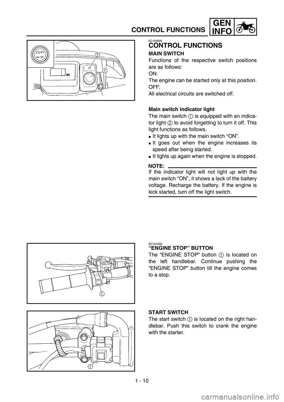
MAIN SWITCH
Functions of the respective switch positions
are as follows:
ON:
The engine can be started only at this position.
OFF:
All electrical circuits are switched off.
Main switch indicator light
The main switch 1 is equipped with an indica-
tor light 2 to avoid forgetting to turn it off. This
light functions as follows.
�It lights up with the main switch “ON”.
�It goes out when the engine increases its
speed after being started.
�It lights up again when the engine is stopped.
NOTE:
If the indicator light will not light up with the
main switch “ON”, it shows a lack of the battery
voltage. Recharge the battery. If the engine is
kick started, turn off the light switch.
EC151000
“ENGINE STOP” BUTTON
The “ENGINE STOP” button 1 is located on
the left handlebar. Continue pushing the
“ENGINE STOP” button till the engine comes
to a stop.
START SWITCH
The start switch 1 is located on the right han-
dlebar. Push this switch to crank the engine
with the starter.
Page 62 of 754

1 - 16
GEN
INFO
STARTING AND BREAK-IN
NOTE:
If the engine fails to start by pushing the start
switch, release the switch, wait a few seconds,
and then try again. Each starting attempt
should be as short as possible to preserve the
battery. Do not crank the engine more than
10 seconds on any one attempt. If the engine
does not start with the starter motor, try using
the kickstarter.
WARNING
�If the starter motor will not turn when
pushing the start switch, stop pushing it
immediately and kick start the engine in
order to avoid the load on the motor.
�Do not open the throttle while kicking the
kickstarter. Otherwise, the kickstarter
may kick back.
7. Return the cold starter knob to its original
position and run the engine at 3,000 ~
5,000 r/min for 1 or 2 minutes.
NOTE:
Since this model is equipped with an accelera-
tor pump, if the engine is raced (the throttle
opened and closed), the air/fuel mixture will be
too rich and the engine may stall. Also unlike a
two-stroke engine, this model can idle.
CAUTION:
Do not warm up the engine for extended
periods of time.
Page 78 of 754
SPEC
2 - 3
GENERAL SPECIFICATIONS
Brake:
Front brake type Single disc brake
Operation Right hand operation
Rear brake type Single disc brake
Operation Right foot operation
Suspension:
Front suspension Telescopic fork
Rear suspension Swingarm (link type monocross suspension)
Shock absorber:
Front shock absorber Coil spring/oil damper
Rear shock absorber Coil spring/gas, oil damper
Wheel travel:
Front wheel travel 300 mm (11.8 in)
Rear wheel travel 315 mm (12.4 in)
Electrical:
Ignition system CDI
Generator system AC magneto
Battery type YTZ7S
Battery voltage/capacity 12 V/6 AH
Specific gravity 1.310
Headlight type: Quartz bulb (halogen)
Bulb wattage
×
quantity:
Headlight 12 V 60/55 W
×
1
Taillight 12 V 21/5 W
×
1
Page 160 of 754

2 - 23
SPEC
CABLE ROUTING DIAGRAM
EC240000
CABLE ROUTING DIAGRAM
1
Fuel tank breather hose
2
Clamp
3
Diode
4
Wire harness
5
Hot starter cable
6
Negative battery lead
7
Starter motor lead
8
TPS (throttle position sen-
sor) lead
9
Neutral switch lead
0
Oil hose
A
Hose holder
B
Radiator hose 4
C
Cylinder head breather hose
D
AC magneto lead
E
Radiator hose 1
F
Oil tank breather hose
G
Brake hose
H
Hose guide
I
Carburetor breather hose
J
Overflow hose
K
Coolant reservoir tank breather
hose
Å
Insert the fuel tank breather
hose into the hole in the steering
shaft cap.
ı
Fasten the diode of the wire har-
ness and rectifier/regulator lead
(at its protecting tube) to the
frame at the white tape for the
diode with a plastic locking tie
and cut off the tie end.
Ç
Fasten the wire harness, recti-
fier/regulator lead, coolant res-
ervoir hose and hot starter cable
to the frame with a plastic lock-
ing tie and cut off the tie end.
Î
Fasten the wire harness, recti-
fier/regulator lead and coolant
reservoir hose to the frame with
a plastic locking tie and cut off
the tie end.
‰
Fasten the wire harness to the
frame at its white tape with a
plastic locking tie and cut off the
tie end.
Page 162 of 754

2 - 24
SPEC
CABLE ROUTING DIAGRAM
Ï
Fasten the wire harness, TPS
lead (in the wire harness),
starter motor lead and negative
battery lead to the frame with a
plastic locking tie and cut off
the tie end.
Ì
Make sure that the TPS cou-
pler does not go out the chas-
sis.
Ó
Fasten the TPS lead to the
frame with a plastic band.
È
Fasten the neutral switch lead
and oil hose together with the
plastic locking ties and cut off
the tie ends.
ÔPass the cylinder head
breather hose through the
hose holders.Fasten the neutral switch lead
to the frame with a plastic band
ends outward.
ÒFasten the neutral switch lead
and AC magneto lead to the
frame with a plastic band ends
outward.
˜Pass the cylinder head
breather hose on the outside of
the radiator hose 1 and on the
inside of the radiator pipe (radi-
ator hose 4).
ˆPass the oil tank breather hose
on the outside of the AC mag-
neto lead, neutral switch lead,
wire harness and cylinder head
breather hose.ØPass the wire harness on the
outside of the neutral switch
lead and AC magneto lead.
∏Fit the brake hose into the
guides on the protector.
ŒPass the wire harness through
the cable guide.
ÂFasten the AC magneto lead
and neutral switch lead to the
cable guide at their protecting
tube with a plastic locking tie
and cut off the tie end.
ÍPass the carburetor breather
hoses, overflow hose and cool-
ant reservoir tank breather
hose so that the hoses do not
contact the rear shock
absorber.
Page 164 of 754

2 - 25
SPECCABLE ROUTING DIAGRAM
1Hot starter cable
2Clutch cable
3Throttle cable (return)
4Throttle cable (pull)
5Ignition coil
6Negative battery lead
7Starter motor lead
8Coolant reservoir tank
breather hose
9Rectifier/regulator
0Cable holder
ACoolant reservoir hose
BRectifier/regulator lead
CClamp
DCDI unit lead
ECDI unit
FCDI unit band
GCDI unit stay (frame)
HCable bracketÅPass the throttle cables, clutch
cable and hot starter cable through
the cable guides.
ıPass the throttle cables, clutch
cable and hot starter cable between
the radiator and frame, then over
the middle radiator mounting boss.
ÇPass the throttle cables and clutch
cable on the outside of the ignition
coil.
ÎPass the carburetor breather hose
(throttle cable cover) through the
hose holder.
‰Fasten the coolant reservoir tank
breather hose and carburetor
breather hoses together with a
plastic locking tie.ÏFasten the grommet of the clutch
cable with the cable holder.
ÌFasten the rectifier/regulator lead to
the frame with a plastic locking tie
and cut off the tie end.
ÓFasten the CDI unit lead to the
frame with a plastic locking tie ends
at the lower of the frame and cut off
the tie end.
ÈInsert the CDI unit band over the
CDI unit stay (frame) as far as pos-
sible.
ÔFasten the starter motor lead and
negative battery lead to the cable
bracket in its slot with a plastic lock-
ing tie and cut off the tie end.
Do not allow the rectifier/regulator
lead to slacken.
Page 168 of 754
2 - 27
SPECCABLE ROUTING DIAGRAM
1Starter motor lead
2Negative battery lead
3Wire harness
4Clamp
5Taillight lead
6Coolant reservoir tank
breather hose
7Coolant reservoir hose
8Positive battery lead
9Starting circuit cut-off
relay
0BatteryÅPosition the starter motor lead,
negative battery lead and wire
harness in the tank damper slit.
ıFasten the wire harness to the
frame with a plastic locking tie and
cut off the tie end.
ÇDo not allow the taillight lead to
slacken.
ÎPass the starter motor lead and
negative battery lead over the car-
buretor.
‰Fasten the coolant reservoir tank
breather hose and coolant reser-
voir hose to the frame with a plas-
tic band.ÏPass the coolant reservoir hose
on the outside of the coolant res-
ervoir tank breather hose.
Page 174 of 754

3 - 3
INSP
ADJ
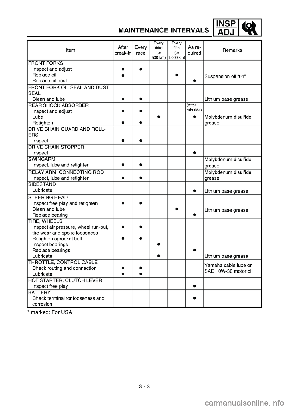
MAINTENANCE INTERVALS
* marked: For USA
FRONT FORKS
Inspect and adjust
Replace oil
Replace oil seal
●
●
●
●
●
Suspension oil “01”
FRONT FORK OIL SEAL AND DUST
SEAL
Clean and lube
●
●
Lithium base grease
REAR SHOCK ABSORBER
Inspect and adjust
Lube
Retighten
●
●
●
●
●
(After
rain ride)
● Molybdenum disulfide
grease
DRIVE CHAIN GUARD AND ROLL-
ERS
Inspect
● ●
DRIVE CHAIN STOPPER
Inspect
●
SWINGARM
Inspect, lube and retighten
● ● Molybdenum disulfide
grease
RELAY ARM, CONNECTING ROD
Inspect, lube and retighten
● ● Molybdenum disulfide
grease
SIDESTAND
Lubricate
●Lithium base grease
STEERING HEAD
Inspect free play and retighten
Clean and lube
Replace bearing
● ●
●
● Lithium base grease
TIRE, WHEELS
Inspect air pressure, wheel run-out,
tire wear and spoke looseness
Retighten sprocket bolt
Inspect bearings
Replace bearings
Lubricate
●
●
●
●
●
●
●
Lithium base grease
THROTTLE, CONTROL CABLE
Check routing and connection
Lubricate
●
●
●
● Yamaha cable lube or
SAE 10W-30 motor oil
HOT STARTER, CLUTCH LEVER
Inspect free play
●
BATTERY
Check terminal for looseness and
corrosion
●
ItemAfter
break-inEvery
race
Every
third
(or
500 km)Every
fifth
(or
1,000 km)As re-
quiredRemarks