Page 57 of 80

PERIODIC MAINTENANCE AND MINOR REPAIR
6-25
1
2
3
4
5
6
7
8
9
EAU23200
Checking and lubricating the
sidestand
The operation of the sidestand should
be checked before each ride, and the
sidestand pivot and metal-to-metal
contact surfaces should be lubricated if
necessary.
WARNING
EWA10730
If the sidestand does not move up
and down smoothly, have a Yamaha
dealer check or repair it.
EAU23250
Lubricating the rear
suspension
The pivoting points of the rear suspen-
sion must be lubricated at the intervals
specified in the periodic maintenance
and lubrication chart.
EAU23271
Checking the front fork
The condition and operation of the front
fork must be checked as follows at the
intervals specified in the periodic main-
tenance and lubrication chart.
To check the condition
WARNING
EWA10750
Securely support the vehicle so that
there is no danger of it falling over.
Check the inner tubes for scratches,
damage and excessive oil leakage.
To check the operation
1. Place the vehicle on a level sur-
face and hold it in an upright posi-
tion.
2. While applying the front brake,
push down hard on the handlebars
several times to check if the front
fork compresses and rebounds
smoothly.
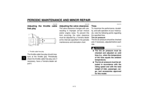
Recommended lubricant:
Lithium-soap-based grease
(all-purpose grease)
1. Grease nipple
Recommended lubricant:
Lithium-soap-based grease1(×2)
Page 58 of 80
PERIODIC MAINTENANCE AND MINOR REPAIR
6-26
2
3
4
5
67
8
9
CAUTION:
ECA10590
If any damage is found or the front
fork does not operate smoothly,
have a Yamaha dealer check or re-
pair it.
EAU23280
Checking the steering
Worn or loose steering bearings may
cause danger. Therefore, the operation
of the steering must be checked as fol-
lows at the intervals specified in the pe-
riodic maintenance and lubrication
chart.
1. Place a stand under the engine to
raise the front wheel off the
ground.
WARNING
EWA10750
Securely support the vehicle so that
there is no danger of it falling over.
2. Hold the lower ends of the front
fork legs and try to move them for-
ward and backward. If any free
play can be felt, have a Yamaha
dealer check or repair the steering.
Page 59 of 80

PERIODIC MAINTENANCE AND MINOR REPAIR
6-27
1
2
3
4
5
6
7
8
9
EAU23290
Checking the wheel bearings
The front and rear wheel bearings must
be checked at the intervals specified in
the periodic maintenance and lubrica-
tion chart. If there is play in the wheel
hub or if the wheel does not turn
smoothly, have a Yamaha dealer check
the wheel bearings.
EAU23361
Battery
A poorly maintained battery will corrode
and discharge quickly. The electrolyte
level, battery lead connections and
breather hose routing should be
checked before each ride and at the in-
tervals specified in the periodic mainte-
nance and lubrication chart.
To check the electrolyte level
1. Remove the seat. (See page 3-8.)
2. Disconnect the negative battery
lead from the battery.
3. Disconnect the positive battery
lead and the battery breather hose
from the battery.
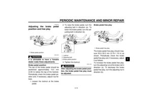
4. Unhook the battery band, and then
pull the battery out of the battery
compartment.5. Place the battery on a level sur-
face, and then check the electro-
lyte level in the battery.
NOTE:
The electrolyte should be between the
minimum and maximum level marks.
1. Battery
2. Negative battery lead
3. Positive battery lead (red)
4. Battery breather hose
5. Battery band
4
1
23 5
Page 60 of 80

PERIODIC MAINTENANCE AND MINOR REPAIR
6-28
2
3
4
5
67
8
9
6. If the electrolyte is at or below the
minimum level mark, add distilled
water to raise the electrolyte to the
maximum level mark.
WARNING
EWA10760
�
Electrolyte is poisonous and
dangerous since it contains sul-
furic acid, which causes severe
burns. Avoid any contact with
skin, eyes or clothing and al-
ways shield your eyes when
working near batteries. In case
of contact, administer the fol-lowing FIRST AID.
�
EXTERNAL: Flush with plenty
of water.
�
INTERNAL: Drink large quan-
tities of water or milk and im-
mediately call a physician.
�
EYES: Flush with water for
15 minutes and seek prompt
medical attention.
�
Batteries produce explosive hy-
drogen gas. Therefore, keep
sparks, flames, cigarettes, etc.,
away from the battery and pro-
vide sufficient ventilation when
charging it in an enclosed
space.
�
KEEP THIS AND ALL BATTER-
IES OUT OF THE REACH OF
CHILDREN.
CAUTION:
ECA10610
Use only distilled water, as tap water
contains minerals that are harmful
to the battery.
7. Place the battery in the battery
compartment, and then hook thebattery band onto the holder.
8. Connect the breather hose to the
battery and make sure that it is
properly routed.
9. Connect and tighten the positive
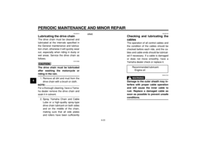
1. Maximum level mark
2. Minimum level mark
1
2
1. Battery breather hose
1. Battery
2. Battery breather hose
1
1
2
Page 61 of 80
 terminal.
10. Connect and tighten the negative
battery lead to the battery’s nega-
ti")
PERIODIC MAINTENANCE AND MINOR REPAIR
6-29
1
2
3
4
5
6
7
8
9
battery lead to the battery’s posi-
tive (+) terminal.
10. Connect and tighten the negative
battery lead to the battery’s nega-
tive (–) terminal.
11. Install the seat.
To store the battery
1. If the vehicle will not be used for
more than one month, remove the
battery, fully charge it, and then
place it in a cool, dry place.
2. If the battery will be stored for more
than two months, check the specif-
ic gravity of the electrolyte at least
once a month and fully charge the
battery whenever necessary.
3. Fully charge the battery before in-
stallation.
4. After installation, make sure that
the battery leads are properly con-
nected to the battery terminals and
that the breather hose is properly
routed, in good condition, and not
obstructed.
CAUTION:
ECA10600
If the breather hose is positioned insuch a way that the frame is ex-
posed to electrolyte or gas expelled
from the battery, the frame could
suffer structural and external dam-
ages.
EAU23500
Replacing the fuse
The fuse holder is located behind panel
B. (See page 6-5.)
If the fuse is blown, replace it as fol-
lows.
1. Turn the key to “OFF” and turn off
all electrical circuits.
2. Remove the blown fuse, and then
install a new fuse of the specified
amperage.
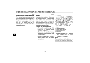
1. Fuse
2. Spare fuse
Specified fuse:
20.0 A
1 2
Page 62 of 80
PERIODIC MAINTENANCE AND MINOR REPAIR
6-30
2
3
4
5
67
8
9
CAUTION:
ECA10640
Do not use a fuse of a higher amper-
age rating than recommended to
avoid causing extensive damage to
the electrical system and possibly a
fire.
3. Turn the key to “ON” and turn on
the electrical circuits to check if the
devices operate.
4. If the fuse immediately blows
again, have a Yamaha dealer
check the electrical system.
EAU23811
Replacing the headlight bulb
This model is equipped with a quartz
bulb headlight. If the headlight bulb
burns out, replace it as follows.
1. Remove cowling A. (See
page 6-5.)
2. Remove the headlight unit by re-
moving the bolts.
3. Disconnect the headlight coupler,
and then remove the headlight
bulb cover.4. Remove the headlight bulb holder
by turning it counterclockwise, and
then remove the defective bulb.
1. Bolt
1(×2)
1. Headlight coupler
2. Headlight bulb cover
1
2
Page 63 of 80
PERIODIC MAINTENANCE AND MINOR REPAIR
6-31
1
2
3
4
5
6
7
8
9
WARNING
EWA10790
Headlight bulbs get very hot. There-
fore, keep flammable products away
from a lit headlight bulb, and do not
touch the bulb until it has cooled
down.
5. Place a new bulb into position, and
then secure it with the bulb holder.
CAUTION:
ECA10660
Do not touch the glass part of the
headlight bulb to keep it free from
oil, otherwise the transparency of
the glass, the luminosity of the bulb,
and the bulb life will be adversely af-fected. Thoroughly clean off any dirt
and fingerprints on the headlight
bulb using a cloth moistened with al-
cohol or thinner.
6. Install the bulb cover, and then
connect the coupler.
7. Install the headlight unit by install-
ing the bolts.8. Install the cowling.
9. Have a Yamaha dealer adjust the
headlight beam if necessary.
1. Headlight bulb holder
1
1. Do not touch the glass part of the bulb.
1
Page 64 of 80
PERIODIC MAINTENANCE AND MINOR REPAIR
6-32
2
3
4
5
67
8
9
EAU24131
Replacing the tail/brake light
bulb
1. Remove the tail/brake light lens by
removing the screws.
2. Remove the defective bulb by
pushing it in and turning it counter-
clockwise.3. Insert a new bulb into the socket,
push it in, and then turn it clock-
wise until it stops.
4. Install the lens by installing the
screws.
CAUTION:
ECA10680
Do not overtighten the screws, oth-
erwise the lens may break.
EAU24210
Replacing a turn signal light
bulb
1. Remove the turn signal lens by re-
moving the screws.
2. Remove the defective bulb by
pushing it in and turning it counter-
clockwise.
3. Insert a new bulb into the socket,
push it in, and then turn it clock-
wise until it stops.
4. Install the lens by installing the
screws.
1. Screw
1(×2)
1. Tail/brake light bulb
1
1. Screw
2. Bulb
3. Turn signal light lens
3
1
2