Page 17 of 80
INSTRUMENT AND CONTROL FUNCTIONS
3-4
1
2
3
4
5
6
7
8
9
EAU12820
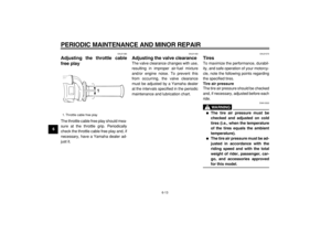
Clutch lever
The clutch lever is located at the left
handlebar grip. To disengage the
clutch, pull the lever toward the handle-
bar grip. To engage the clutch, release
the lever. The lever should be pulled
rapidly and released slowly for smooth
clutch operation.
The clutch lever is equipped with a
clutch switch, which is part of the igni-
tion circuit cut-off system. (See
page 3-11.)
EAU12870
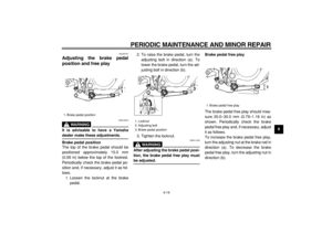
Shift pedal
The shift pedal is located on the left
side of the engine and is used in com-
bination with the clutch lever when
shifting the gears of the 5-speed con-
stant-mesh transmission equipped on
this motorcycle.
EAU12890
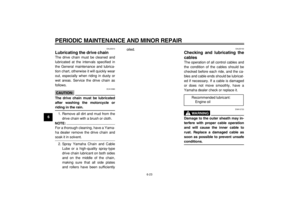
Brake lever
The brake lever is located at the right
handlebar grip. To apply the front
brake, pull the lever toward the handle-
bar grip.
1. Clutch lever
1
1. Shift pedal
1
1. Brake lever
1
Page 18 of 80
INSTRUMENT AND CONTROL FUNCTIONS
3-5
2
34
5
6
7
8
9
EAU12941
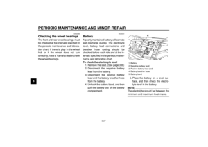
Brake pedal
The brake pedal is on the right side of
the motorcycle. To apply the rear
brake, press down on the brake pedal.
EAU32280
Fuel tank cap
To remove the fuel tank cap
1. Insert the key into the lock and turn
it 1/3 turn counterclockwise.
2. Turn the fuel tank cap 1/3 turn
counterclockwise and pull it off.
To install the fuel tank cap
1. Insert the fuel tank cap into the
tank opening with the key inserted
in the lock, and then turn the cap 1/
3 turn clockwise.
2. Turn the key 1/3 turn clockwise,
and then remove it.
NOTE:
The fuel tank cap cannot be installedunless the key is in the lock. In addition,
the key cannot be removed if the cap is
not properly installed and locked.
WARNING
EWA10120
Make sure that the fuel tank cap is
properly closed and locked before
riding.
1. Brake pedal
1
1. Fuel tank cap
2. Unlock.
1
2
Page 19 of 80

INSTRUMENT AND CONTROL FUNCTIONS
3-6
1
2
3
4
5
6
7
8
9
EAU13210
Fuel
Make sure that there is sufficient fuel in
the tank. Fill the fuel tank to the bottom
of the filler tube as shown.
WARNING
EWA10880
�
Do not overfill the fuel tank, oth-
erwise it may overflow when the
fuel warms up and expands.
�
Avoid spilling fuel on the hot en-
gine.
CAUTION:
ECA10070
Immediately wipe off spilled fuel
with a clean, dry, soft cloth, sincefuel may deteriorate painted surfac-
es or plastic parts.
EAU13241EAU13560
Fuel cock
The fuel cock supplies fuel from the
tank to the carburetor while filtering it al-
so.
The fuel cock has three positions:
OFF
With the lever in this position, fuel will
not flow. Always return the lever to this
position when the engine is not running.
1. Fuel tank filler tube
2. Fuel level
1
2
Recommended fuel:
Regular unleaded gasoline
only
Fuel tank capacity:
7.0 L (1.85 US gal)
(1.54 Imp.gal)
Fuel reserve amount:
1.7 L (0.45 US gal)
(0.37 Imp.gal)
1. Arrow mark positioned over “OFF”
RES
ONFUEL
OFF
1
Page 20 of 80
INSTRUMENT AND CONTROL FUNCTIONS
3-7
2
34
5
6
7
8
9 ON
With the lever in this position, fuel flows
to the carburetor. Normal riding is done
with the lever in this position.
RES
This indicates reserve. If you run out offuel while riding, move the lever to this
position. Fill the tank at the first oppor-
tunity. Be sure to set the lever back to
“ON” after refueling!
EAU13600
Starter (choke) knob “”
Starting a cold engine requires a richer
air-fuel mixture, which is supplied by
the starter (choke).
Move the knob in direction (a) to turn on
the starter (choke).
Move the knob in direction (b) to turn off
the starter (choke).
1. Arrow mark positioned over “ON”
1. Arrow mark positioned over “RES”
ON
FUEL
RES
OFF
1
ON
OFF
ONFUEL RES
1
RES
1. Starter (choke) knob “”
1(a) (b)
Page 21 of 80
INSTRUMENT AND CONTROL FUNCTIONS
3-8
1
2
3
4
5
6
7
8
9
EAU13660
Kickstarter
If the engine fails to start by pushing the
start switch, try to start it by using the
kickstarter. To start the engine, fold out
the kickstarter lever, move it down light-
ly with your foot until the gears engage,
and then push it down smoothly but
forcefully. This model is equipped with
a primary kickstarter, allowing the en-
gine to be started in any gear if the
clutch is disengaged. However, shifting
the transmission into the neutral posi-
tion before starting is recommended.
EAU13970
Seat
To remove the seat
Remove the bolts, and then pull the
seat off.
To install the seat
1. Insert the projection on the front of
the seat into the seat holder as
shown.2. Place the seat in the original posi-
tion, and then tighten the bolts.
NOTE:
Make sure that the seat is properly se-
cured before riding.
1. Kickstarter
1
1. Bolt1(×2)
1. Projection
2. Seat holder
1
2
Page 22 of 80

INSTRUMENT AND CONTROL FUNCTIONS
3-9
2
34
5
6
7
8
9
EAU14280
Helmet holder
To open the helmet holder, insert the
key into the lock, and then turn the key
as shown.
To lock the helmet holder, place it in the
original position, and then remove the
key.
WARNING
EWA10160
Never ride with a helmet attached to
the helmet holder, since the helmet
may hit objects, causing loss of con-
trol and possibly an accident.
EAU15090
Shock absorber
WARNING
EWA10220
This shock absorber contains highly
pressurized nitrogen gas. For prop-
er handling, read and understand
the following information before
handling the shock absorber. The
manufacturer cannot be held re-
sponsible for property damage or
personal injury that may result from
improper handling.
�
Do not tamper with or attempt to
open the gas cylinder.
�
Do not subject the shock ab-
sorber to an open flame or other
high heat sources, otherwise it
may explode due to excessive
gas pressure.
�
Do not deform or damage the
gas cylinder in any way, as this
will result in poor damping per-
formance.
�
Always have a Yamaha dealer
service the shock absorber.
EAU15110
Carrier
WARNING
EWA10170
�
Do not exceed the load limit of
3 kg (7 lb) for the carrier.
�
Do not exceed the maximum
load of 180 kg (397 lb) for the ve-
hicle.
1. Helmet holder
1
1. Carrier
1
Page 23 of 80

INSTRUMENT AND CONTROL FUNCTIONS
3-10
1
2
3
4
5
6
7
8
9
EAU15170
Luggage strap holders
There are four luggage strap holders
below the carrier.
EAU15300
Sidestand
The sidestand is located on the left side
of the frame. Raise the sidestand or
lower it with your foot while holding the
vehicle upright.
NOTE:
The built-in sidestand switch is part of
the ignition circuit cut-off system, which
cuts the ignition in certain situations.
(See further down for an explanation of
the ignition circuit cut-off system.)
WARNING
EWA10240
The vehicle must not be ridden with
the sidestand down, or if the side-
stand cannot be properly moved up
(or does not stay up), otherwise the
sidestand could contact the ground
and distract the operator, resulting
in a possible loss of control. Yama-
ha’s ignition circuit cut-off system
has been designed to assist the op-
erator in fulfilling the responsibility
of raising the sidestand before start-
ing off. Therefore, check this systemregularly as described below and
have a Yamaha dealer repair it if it
does not function properly.
1. Luggage strap holder
1(×2)
1(×2)
Page 24 of 80
INSTRUMENT AND CONTROL FUNCTIONS
3-11
2
34
5
6
7
8
9
EAU15311
Ignition circuit cut-off system
The ignition circuit cut-off system (com-
prising the sidestand switch, clutch
switch and neutral switch) has the fol-
lowing functions.
�
It prevents starting when the trans-
mission is in gear and the side-
stand is up, but the clutch lever is
not pulled.
�
It prevents starting when the trans-
mission is in gear and the clutch le-
ver is pulled, but the sidestand is
still down.
�
It cuts the running engine when the
transmission is in gear and the sid-
estand is moved down.
Periodically check the operation of the
ignition circuit cut-off system according
to the following procedure.
WARNING
EWA10250
If a malfunction is noted, have a
Yamaha dealer check the system be-
fore riding.