Page 41 of 80

PERIODIC MAINTENANCE AND MINOR REPAIR
6-9
1
2
3
4
5
6
7
8
9
NOTE:
Skip steps 4–9 if the oil filter element is
not being cleaned.
4. Remove the oil filter element drain
bolt to drain the oil from the oil filter
element.5. Remove the oil filter element cover
by removing the bolts.
6. Remove the oil filter element and
O-rings.7. Check the O-ring for damage and
replace it if necessary.
8. Clean the oil filter element with sol-
vent, and then install it.
NOTE:
Check the oil filter element for damage
and replace it if necessary.
9. Install the oil filter element cover by
installing the bolts and the drain
bolt, then tightening them to the
specified torques.
NOTE:
Make sure that the O-rings are properly
seated.
10. Clean the oil strainer with solvent,
and then check it for damage and
replace it if necessary.
11. Install the oil strainer, compression
spring, O-ring and engine oil drain
1. O-ring
2. Compression spring
3. Oil strainer
3
21
1. Oil filter element cover
2. Bolt
3. Oil filter element drain bolt
1. Oil filter element
2. O-ring
1
3
2(×2)
1 2
2
Tightening torques:
Oil filter element cover bolt:
10 Nm (1.0 m·kgf, 7.2 ft·lbf)
Oil filter element drain bolt:
10 Nm (1.0 m·kgf, 7.2 ft·lbf)
Page 42 of 80

PERIODIC MAINTENANCE AND MINOR REPAIR
6-10
2
3
4
5
67
8
9
bolt, and then tighten the drain bolt
to the specified torque.
12. Add the specified amount of the
recommended engine oil, and then
install and tighten the oil filler cap.
CAUTION:
ECA11620
�
In order to prevent clutch slip-
page (since the engine oil also
lubricates the clutch), do not
mix any chemical additives. Do
not use oils with a diesel speci-
fication of “CD” or oils of a high-er quality than specified. In
addition, do not use oils labeled
“ENERGY CONSERVING II” or
higher.
�
Make sure that no foreign mate-
rial enters the crankcase.
13. Start the engine, and then let it idle
for several minutes while checking
it for oil leakage. If oil is leaking, im-
mediately turn the engine off and
check for the cause.
14. Turn the engine off, and then
check the oil level and correct it if
necessary.
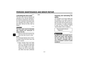
EAU20830
Cleaning the air filter element
and check hose
The air filter element should be cleaned
at the intervals specified in the periodic
maintenance and lubrication chart.
Clean the air filter element more fre-
quently if you are riding in unusually
wet or dusty areas. In addition, the air
filter check hose must be frequently
checked and cleaned if necessary.
To clean the air filter element
1. Remove panel A. (See page 6-5.)
2. Remove the air filter case cover by
removing the screws.
3. Pull the air filter element out.
Tightening torque:
Engine oil drain bolt:
43 Nm (4.3 m·kgf, 31 ft·lbf)
Recommended engine oil:
See page 8-1.
Oil quantity:
Without oil filter element removal:
1.00 L (1.06 US qt)
(0.88 Imp.qt)
With oil filter element removal:
1.10 L (1.16 US qt)
(0.97 Imp.qt)
1. Air filter case cover
2. Screw
1
2(×2)
2(×2)
Page 43 of 80

PERIODIC MAINTENANCE AND MINOR REPAIR
6-11
1
2
3
4
5
6
7
8
9
4. Remove the sponge material from
the air filter element frame, clean it
with solvent, and then squeeze the
remaining solvent out.
5. Apply oil of the recommended type
to the entire surface of the spongematerial, and then squeeze the ex-
cess oil out.
NOTE:
The sponge material should be wet but
not dripping.
6. Pull the sponge material over the
air filter element frame.
7. Insert the element into the air filter
case.
CAUTION:
ECA10480
�
Make sure that the air filter ele-
ment is properly seated in the
air filter case.
�
The engine should never be op-
erated without the air filter ele-
ment installed, otherwise the
piston(s) and/or cylinder(s) may
become excessively worn.
8. Install the air filter case cover by in-
stalling the screws.
9. Install the panel.
To clean the air filter check hose
1. Check the hose at the bottom of
the air filter case for accumulated
dirt or water.
2. If dirt or water is visible, remove
the hose, clean it, and then install
it.
1. Sponge material
2. Air filter element frame
1
2
Recommended oil:
Engine oil
1. Hose
1
Page 44 of 80

PERIODIC MAINTENANCE AND MINOR REPAIR
6-12
2
3
4
5
67
8
9
EAU21280
Adjusting the carburetor
The carburetor is an important part of
the engine and requires very sophisti-
cated adjustment. Therefore, most car-
buretor adjustments should be left to a
Yamaha dealer, who has the neces-
sary professional knowledge and expe-
rience. The adjustment described in the
following section, however, may be ser-
viced by the owner as part of routine
maintenance.
CAUTION:
ECA10550
The carburetor has been set and ex-
tensively tested at the Yamaha fac-
tory. Changing these settings
without sufficient technical knowl-
edge may result in poor perfor-
mance of or damage to the engine.
EAU21330
Adjusting the engine idling
speed
The engine idling speed must be
checked and, if necessary, adjusted as
follows at the intervals specified in the
periodic maintenance and lubrication
chart.
NOTE:
A diagnostic tachometer is needed to
make this adjustment.
1. Attach the tachometer to the spark
plug lead.
2. Start the engine and warm it up
for several minutes at
1,000–2,000 r/min while occa-
sionally revving it to
4,000–5,000 r/min.
NOTE:
The engine is warm when it quickly re-
sponds to the throttle.
3. Check the engine idling speed
and, if necessary, adjust it to spec-
ification by turning the throttle stop
screw. To increase the engine
idling speed, turn the screw in di-rection (a). To decrease the en-
gine idling speed, turn the screw in
direction (b).
NOTE:
If the specified idling speed cannot be
obtained as described above, have a
Yamaha dealer make the adjustment.
1. Throttle stop screw
Engine idling speed:
1350–1550 r/min
(a)
1
(b)
Page 45 of 80

PERIODIC MAINTENANCE AND MINOR REPAIR
6-13
1
2
3
4
5
6
7
8
9
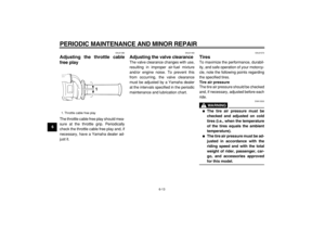
EAU21380
Adjusting the throttle cable
free play
The throttle cable free play should mea-
sure at the throttle grip. Periodically
check the throttle cable free play and, if
necessary, have a Yamaha dealer ad-
just it.
EAU21400
Adjusting the valve clearance
The valve clearance changes with use,
resulting in improper air-fuel mixture
and/or engine noise. To prevent this
from occurring, the valve clearance
must be adjusted by a Yamaha dealer
at the intervals specified in the periodic
maintenance and lubrication chart.
EAU21570
Tires
To maximize the performance, durabil-
ity, and safe operation of your motorcy-
cle, note the following points regarding
the specified tires.
Tire air pressure
The tire air pressure should be checked
and, if necessary, adjusted before each
ride.
WARNING
EWA10500
�
The tire air pressure must be
checked and adjusted on cold
tires (i.e., when the temperature
of the tires equals the ambient
temperature).
�
The tire air pressure must be ad-
justed in accordance with the
riding speed and with the total
weight of rider, passenger, car-
go, and accessories approved
for this model.
1. Throttle cable free play
1
Page 46 of 80

PERIODIC MAINTENANCE AND MINOR REPAIR
6-14
2
3
4
5
67
8
9
WARNING
EWA10530
Proper loading of your motorcycle is
important for several characteristics
of your motorcycle; such as han-
dling, braking, performance andsafety. Do not carry loosely packed
items that can shift. Securely pack
your heaviest items close to the cen-
ter of the motorcycle, and distribute
the weight evenly from side to side.
Check the condition and pressure of
your tires. NEVER OVERLOAD
YOUR MOTORCYCLE. Make sure
the total weight of the cargo, rider,
passenger, and accessories (fairing,
saddlebags, etc. if approved for this
model) does not exceed the maxi-
mum load of the motorcycle. Opera-
tion of an overloaded motorcycle
could cause tire damage, an acci-
dent, or even injury.Tire inspection
The tires must be checked before each
ride. If the tire shows crosswise lines
(minimum tread depth), if the tire has a
nail or glass fragments in it, or if the
sidewall is cracked, have a Yamaha
dealer replace the tire immediately.
NOTE:
The tire tread depth limits may differ
from country to country. Always comply
Tire air pressure (measured on
cold tires):
0–90 kg (0–198 lb) :
Front:
125 kPa (18 psi) (1.25 kgf/cm
2
)
Rear:
125 kPa (18 psi) (1.25 kgf/cm
2
)
90–180 kg (198–397 lb) :
Front:
150 kPa (22 psi) (1.50 kgf/cm
2
)
Rear:
175 kPa (25 psi) (1.75 kgf/cm
2
)
Off-road riding:
Front:
125 kPa (18 psi) (1.25 kgf/cm
2
)
Rear:
125 kPa (18 psi) (1.25 kgf/cm
2
)
Maximum load*:
180 kg (397 lb)
* Total weight of rider, passenger,
cargo and accessories
1. Tire sidewall
2. Tire wear indicator
3. Tire tread depth
Minimum tire tread depth (front
and rear):
1.0 mm (0.04 in)
123
Page 47 of 80

PERIODIC MAINTENANCE AND MINOR REPAIR
6-15
1
2
3
4
5
6
7
8
9
with the local regulations.
Tire information
This motorcycle is equipped with tube
tires.
WARNING
EWA10460
�
The front and rear tires should
be of the same make and de-
sign, otherwise the handling
characteristics of the vehicle
cannot be guaranteed.
�
After extensive tests, only the
tires listed below have been
approved for this model by
Yamaha Motor Co., Ltd.
WARNING
EWA10560
�
It is dangerous to ride with a
worn-out tire. When a tire tread
begins to show crosswise lines,
have a Yamaha dealer replace
the tire immediately.
�
The replacement of all wheel-
and brake-related parts, includ-
ing the tires, should be left to a
Yamaha dealer, who has the
necessary professional knowl-
edge and experience.
�
It is not recommended to patch
a punctured tube. If unavoid-
able, however, patch the tubevery carefully and replace it as
soon as possible with a
high-quality product. Front tire:
Size:
130/80-18M/C 66P
Manufacturer/model:
BRIDGESTONE/TW31
Rear tire:
Size:
180/80-14M/C 78P
Manufacturer/model:
BRIDGESTONE/TW34
Page 48 of 80

PERIODIC MAINTENANCE AND MINOR REPAIR
6-16
2
3
4
5
67
8
9
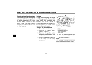
EAU21940
Spoke wheels
To maximize the performance, durabil-
ity, and safe operation of your motorcy-
cle, note the following points regarding
the specified wheels.
�
The wheel rims should be checked
for cracks, bends or warpage, and
the spokes for looseness or dam-
age before each ride. If any dam-
age is found, have a Yamaha
dealer replace the wheel. Do not
attempt even the smallest repair to
the wheel. A deformed or cracked
wheel must be replaced.
�
The wheel should be balanced
whenever either the tire or wheel
has been changed or replaced. An
unbalanced wheel can result in
poor performance, adverse han-
dling characteristics, and a short-
ened tire life.
�
Ride at moderate speeds after
changing a tire since the tire sur-
face must first be “broken in” for it
to develop its optimal characteris-
tics.
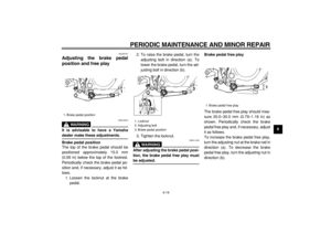
EAU22040
Adjusting the clutch lever free
play
The clutch lever free play should mea-
sure 10.0–15.0 mm (0.39–0.59 in) as
shown. Periodically check the clutch le-
ver free play and, if necessary, adjust it
as follows.
1. Loosen the locknut at the clutch le-
ver.
2. To increase the clutch lever free
play, turn the adjusting bolt in di-
rection (a). To decrease the clutch
lever free play, turn the adjusting
bolt in direction (b).3. If the specified clutch lever free
play could be obtained as de-
scribed above, tighten the locknut
and skip the rest of the procedure,
otherwise proceed as follows.
4. Fully turn the adjusting bolt at the
clutch lever in direction (a) to loos-
en the clutch cable.
5. Loosen the locknut at the crank-
case.
6. To increase the clutch lever free
play, turn the adjusting nut in direc-
tion (a). To decrease the clutch le-
ver free play, turn the adjusting nut
in direction (b).
1. Locknut (clutch lever)
2. Adjusting bolt
3. Clutch lever free play
1
2
3(a)
(b)
1. Locknut (crankcase)
2. Adjusting nut
(b)(a)
2
1