Page 9 of 80
. When loading within
this weight limit, keep the following in
mind:
�
Cargo and accessory weight
should be kept as")
SAFETY INFORMATION
1-3
1
not exceed the maximum load limit of
180 kg (397 lb). When loading within
this weight limit, keep the following in
mind:
�
Cargo and accessory weight
should be kept as low and close to
the motorcycle as possible. Make
sure to distribute the weight as
evenly as possible on both sides of
the motorcycle to minimize imbal-
ance or instability.
�
Shifting weights can create a sud-
den imbalance. Make sure that ac-
cessories and cargo are securely
attached to the motorcycle before
riding. Check accessory mounts
and cargo restraints frequently.
�
Never attach any large or heavy
items to the handlebar, front fork,
or front fender. These items, in-
cluding such cargo as sleeping
bags, duffel bags, or tents, can
create unstable handling or a slow
steering response.
Accessories
Genuine Yamaha accessories havebeen specifically designed for use on
this motorcycle. Since Yamaha cannot
test all other accessories that may be
available, you must personally be re-
sponsible for the proper selection, in-
stallation and use of non-Yamaha
accessories. Use extreme caution
when selecting and installing any ac-
cessories.
Keep the following guidelines in mind,
as well as those provided under “Load-
ing” when mounting accessories.
�
Never install accessories or carry
cargo that would impair the perfor-
mance of your motorcycle. Care-
fully inspect the accessory before
using it to make sure that it does
not in any way reduce ground
clearance or cornering clearance,
limit suspension travel, steering
travel or control operation, or ob-
scure lights or reflectors.
�
Accessories fitted to the handle-
bar or the front fork area can
create instability due to improper
weight distribution or aerody-namic changes. If accessories
are added to the handlebar or
front fork area, they must be as
lightweight as possible and
should be kept to a minimum.
�
Bulky or large accessories may
seriously affect the stability of
the motorcycle due to aerody-
namic effects. Wind may at-
tempt to lift the motorcycle, or
the motorcycle may become un-
stable in cross winds. These ac-
cessories may also cause
instability when passing or being
passed by large vehicles.
�
Certain accessories can dis-
place the operator from his or
her normal riding position. This
improper position limits the free-
dom of movement of the opera-
tor and may limit control ability,
therefore, such accessories are
not recommended.
�
Use caution when adding electri-
cal accessories. If electrical acces-
sories exceed the capacity of the
Page 10 of 80

SAFETY INFORMATION
1-4
1
motorcycle’s electrical system an
electric failure could result, which
could cause a dangerous loss of
lights or engine power.
Gasoline and exhaust gas
�
GASOLINE IS HIGHLY FLAMMA-
BLE:
�
Always turn the engine off when
refueling.
�
Take care not to spill any gaso-
line on the engine or exhaust
system when refueling.
�
Never refuel while smoking or in
the vicinity of an open flame.
�
Never start the engine or let it run
for any length of time in a closed
area. The exhaust fumes are poi-
sonous and may cause loss of
consciousness and death within a
short time. Always operate your
motorcycle in an area that has ad-
equate ventilation.
�
Always turn the engine off before
leaving the motorcycle unattended
and remove the key from the main
switch. When parking the motorcy-cle, note the following:
�
The engine and exhaust system
may be hot, therefore, park the
motorcycle in a place where pe-
destrians or children are not like-
ly to touch these hot areas.
�
Do not park the motorcycle on a
slope or soft ground, otherwise it
may fall over.
�
Do not park the motorcycle near
a flammable source (e.g., a ker-
osene heater, or near an open
flame), otherwise it could catch
fire.
�
When transporting the motorcycle
in another vehicle, make sure that
it is kept upright and that the fuel
cock(s) are turned to “ON” or
“RES” (for vacuum type)/“OFF”
(for manual type). If the motorcycle
should lean over, gasoline may
leak out of the carburetor or fuel
tank.
�
If you should swallow any gaso-
line, inhale a lot of gasoline vapor,
or allow gasoline to get into youreyes, see your doctor immediate-
ly. If any gasoline spills on your
skin or clothing, immediately wash
the affected area with soap and
water and change your clothes.
Page 11 of 80
2-1
1
2
3
4
5
6
7
8
9
DESCRIPTION
EAU10410
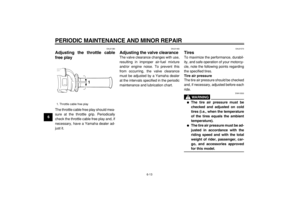
Left view
1
2
3
4 5 76
1. Fuel cock (page 3-6)
2. Helmet holder (page 3-9)
3. Luggage strap holder (page 3-10)
4. Drive chain slack adjusting plate
5. Air filter element (page 6-10)
6. Starter (choke) knob (page 3-7)
7. Shift pedal (page 3-4)
Page 12 of 80
DESCRIPTION
2-2
2
3
4
5
6
7
8
9
EAU10420
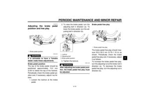
Right view
12
654 3
7
8
9
1. Carrier
2. Battery (page 6-27)
3. Kickstarter (page 3-8)
4. Engine oil filter element (page 6-7)
5. Engine oil level check window (page 6-7)
6. Brake pedal (page 3-5)
7. Owner’s tool kit (page 6-1)
8. Fuse (page 6-29)9. Luggage strap holder (page 3-10)
Page 13 of 80
DESCRIPTION
2-3
1
2
3
4
5
6
7
8
9
EAU10430
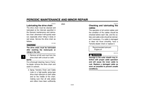
Controls and instruments
12 3 4
567
8
9
1. Clutch lever (page 3-4)
2. Left handlebar switches (page 3-3)
3. Speedometer unit (page 3-2)
4. Main switch/steering lock (page 3-1)
5. Indicator lights (page 3-2)
6. Right handlebar switches (page 3-3)
7. Brake lever (page 3-4)
8. Throttle grip (page 6-13)9. Fuel tank cap (page 3-5)
Page 14 of 80
INSTRUMENT AND CONTROL FUNCTIONS
3-1
2
34
5
6
7
8
9
EAU10460
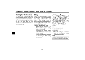
Main switch/steering lock
The main switch/steering lock controls
the ignition and lighting systems, and is
used to lock the steering. The various
positions are described below.
EAU10510
ON
All electrical systems are supplied with
power, and the headlight, meter light-
ing, taillight and position lights come
on, and the engine can be started. The
key cannot be removed.
EAU10660
OFF
All electrical systems are off. The key
can be removed.
EAU10710
LOCK
The steering is locked, and all electrical
systems are off. The key can be re-
moved.
To lock the steering
Turn the handlebars all the way to the
left or right.
1. Push the key in from the “OFF” po-
sition, release it, and then turn it to
“LOCK”.
2. Remove the key.To unlock the steering
Insert the key and turn it to “OFF”.
WARNING
EWA10070
Never turn the key to “LOCK” while
the motorcycle is moving.
LOCKOFFON
1. Push.
2. Release.
3. Turn.
12
3
Page 15 of 80

INSTRUMENT AND CONTROL FUNCTIONS
3-2
1
2
3
4
5
6
7
8
9
EAU10980
Indicator lights
EAU11020
Turn signal indicator light “”
This indicator light flashes when the
turn signal switch is pushed to the left or
right.
EAU11060
Neutral indicator light “”
This indicator light comes on when the
transmission is in the neutral position.
EAU11080
High beam indicator light “”
This indicator light comes on when the
high beam of the headlight is switched
on.
EAU11630
Speedometer unit
The speedometer unit is equipped with
a speedometer, an odometer and a
tripmeter. The speedometer shows
riding speed. The odometer shows the
total distance traveled. The tripmeter
shows the distance traveled since it
was last set to zero with the reset knob.
The tripmeter can be used to estimate
the distance that can be traveled with a
full tank of fuel. This information will en-
able you to plan future fuel stops.
1. Turn signal indicator light “ ”
2. High beam indicator light “ ”
3. Neutral indicator light “ ”
3
12
1. Speedometer
2. Odometer
3. Tripmeter
4. Reset knob
4
23 1
Page 16 of 80

INSTRUMENT AND CONTROL FUNCTIONS
3-3
2
34
5
6
7
8
9
EAU12341
Handlebar switches
LeftRight
EAU12400
Dimmer switch “/”
Set this switch to “ ” for the high
beam and to “ ” for the low beam.
EAU12460
Turn signal switch “/”
To signal a right-hand turn, push this
switch to “ ”. To signal a left-hand
turn, push this switch to “ ”. When re-
leased, the switch returns to the center
position. To cancel the turn signal
lights, push the switch in after it has re-
turned to the center position.
EAU12500
Horn switch “”
Press this switch to sound the horn.
EAU12660
Engine stop switch “/”
Set this switch to “ ” before starting
the engine. Set this switch to “ ” to
stop the engine in case of an emergen-
cy, such as when the vehicle overturns
or when the throttle cable is stuck.
EAU12710
Start switch “”
Push this switch to crank the engine
with the starter.
CAUTION:
ECA10050
See page 5-1 for starting instruc-
tions prior to starting the engine.
1. Dimmer switch “ / ”
2. Turn signal switch “ / ”
3. Horn switch “ ”
1
2
3
1. Engine stop switch “ / ”
2. Start switch “ ”
12


2. Helmet holder (page 3-9)
3. Luggage strap holder (page 3-10)
4. Drive chain slack adjusting plate")

3. Kickstarter (page 3-8)
4. Engine oil filter element (page 6-7)
5. Engine oil level che")

2. Left handlebar switches (page 3-3)
3. Speedometer unit (page 3-2)
4. Main swit")
