Page 81 of 136

A09514
Front Mark
(Protrusion)
A09493
90�
90�
A09490
Front
Painted Mark
A09495
± ENGINE MECHANICALCYLINDER BLOCK (1CD±FTV)
14±41
1CD±FTV ENGINE REPAIR MANUAL (RM927E)
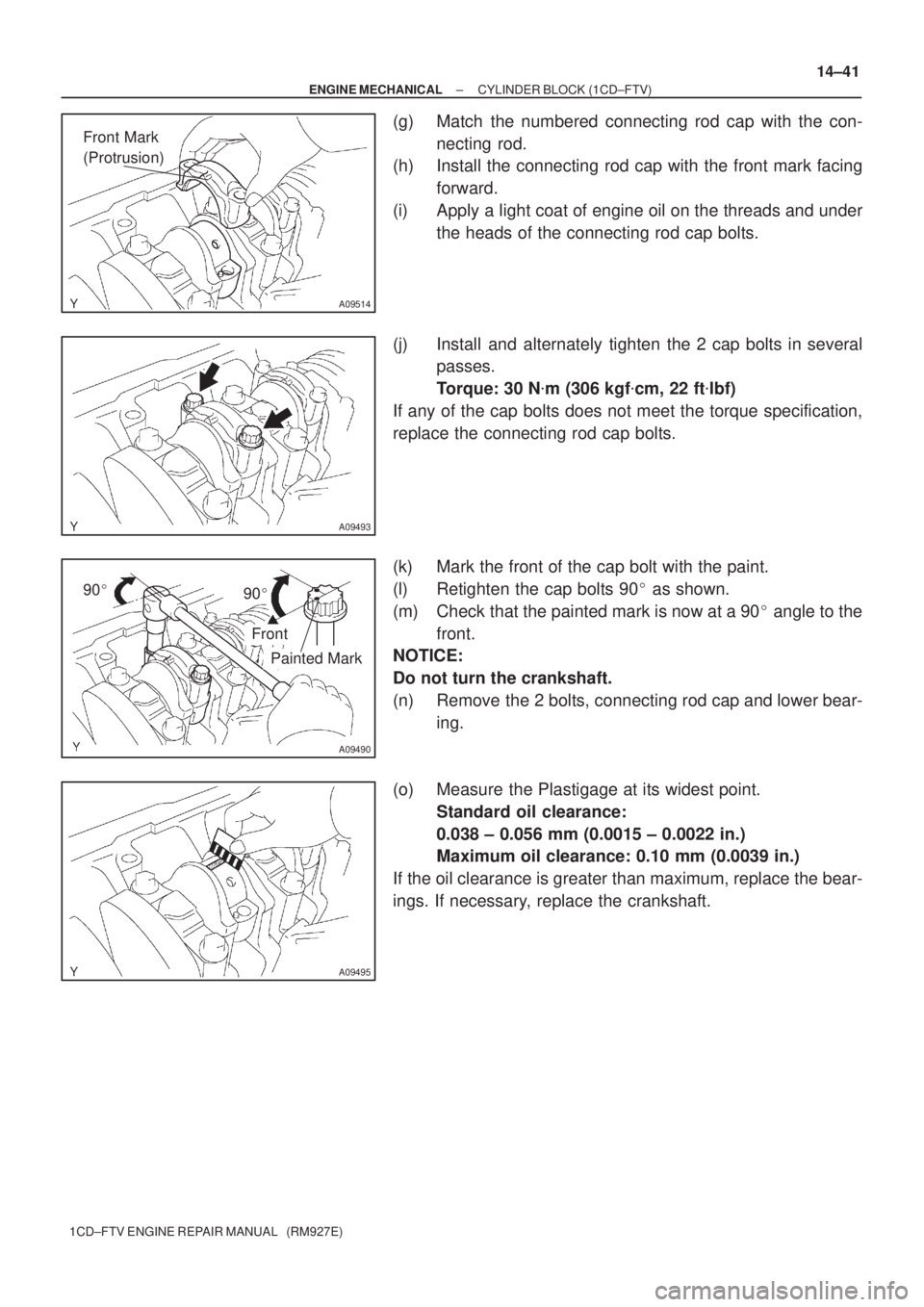
(g) Match the numbered connecting rod cap with the con-
necting rod.
(h) Install the connecting rod cap with the front mark facing
forward.
(i) Apply a light coat of engine oil on the threads and under
the heads of the connecting rod cap bolts.
(j) Install and alternately tighten the 2 cap bolts in several
passes.
Torque: 30 N�m (306 kgf�cm, 22 ft�lbf)
If any of the cap bolts does not meet the torque specification,
replace the connecting rod cap bolts.
(k) Mark the front of the cap bolt with the paint.
(l) Retighten the cap bolts 90� as shown.
(m) Check that the painted mark is now at a 90� angle to the
front.
NOTICE:
Do not turn the crankshaft.
(n) Remove the 2 bolts, connecting rod cap and lower bear-
ing.
(o) Measure the Plastigage at its widest point.
Standard oil clearance:
0.038 ± 0.056 mm (0.0015 ± 0.0022 in.)
Maximum oil clearance: 0.10 mm (0.0039 in.)
If the oil clearance is greater than maximum, replace the bear-
ings. If necessary, replace the crankshaft.
Page 82 of 136

A09472
No.1
No.2
No.3
No.4
Mark
0,1 or 2Mark
1, 2, 3, 4 or 5Mark
1, 2 or 3
A56037
Ridge reamer
14±42
± ENGINE MECHANICALCYLINDER BLOCK (1CD±FTV)
1CD±FTV ENGINE REPAIR MANUAL (RM927E)
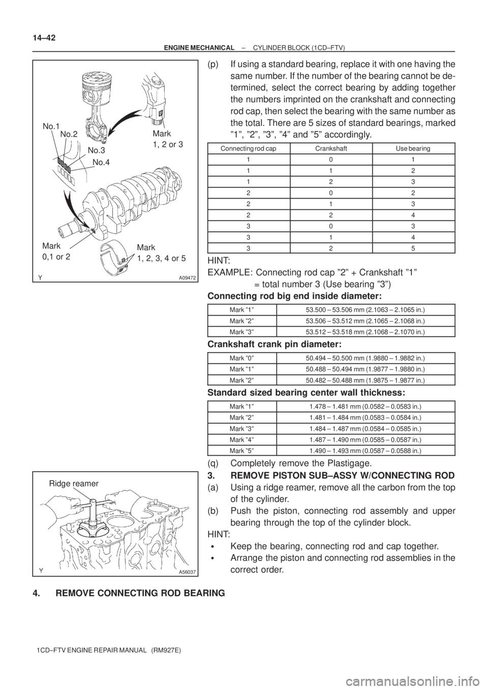
(p) If using a standard bearing, replace it with one having the
same number. If the number of the bearing cannot be de-
termined, select the correct bearing by adding together
the numbers imprinted on the crankshaft and connecting
rod cap, then select the bearing with the same number as
the total. There are 5 sizes of standard bearings, marked
º1º, º2º, º3º, º4º and º5º accordingly.
Connecting rod capCrankshaftUse bearing
101
112
123
202
213
224
303
314
325
HINT:
EXAMPLE: Connecting rod cap º2º + Crankshaft º1º
= total number 3 (Use bearing º3º)
Connecting rod big end inside diameter:
Mark º1º53.500 ± 53.506 mm (2.1063 ± 2.1065 in.)
Mark º2º53.506 ± 53.512 mm (2.1065 ± 2.1068 in.)
Mark º3º53.512 ± 53.518 mm (2.1068 ± 2.1070 in.)
Crankshaft crank pin diameter:
Mark º0º50.494 ± 50.500 mm (1.9880 ± 1.9882 in.)
Mark º1º50.488 ± 50.494 mm (1.9877 ± 1.9880 in.)
Mark º2º50.482 ± 50.488 mm (1.9875 ± 1.9877 in.)
Standard sized bearing center wall thickness:
Mark º1º1.478 ± 1.481 mm (0.0582 ± 0.0583 in.)
Mark º2º1.481 ± 1.484 mm (0.0583 ± 0.0584 in.)
Mark º3º1.484 ± 1.487 mm (0.0584 ± 0.0585 in.)
Mark º4º1.487 ± 1.490 mm (0.0585 ± 0.0587 in.)
Mark º5º1.490 ± 1.493 mm (0.0587 ± 0.0588 in.)
(q) Completely remove the Plastigage.
3. REMOVE PISTON SUB±ASSY W/CONNECTING ROD
(a) Using a ridge reamer, remove all the carbon from the top
of the cylinder.
(b) Push the piston, connecting rod assembly and upper
bearing through the top of the cylinder block.
HINT:
�Keep the bearing, connecting rod and cap together.
�Arrange the piston and connecting rod assemblies in the
correct order.
4. REMOVE CONNECTING ROD BEARING
Page 83 of 136

A09496
A09497
A08026
A09503
± ENGINE MECHANICALCYLINDER BLOCK (1CD±FTV)
14±43
1CD±FTV ENGINE REPAIR MANUAL (RM927E)
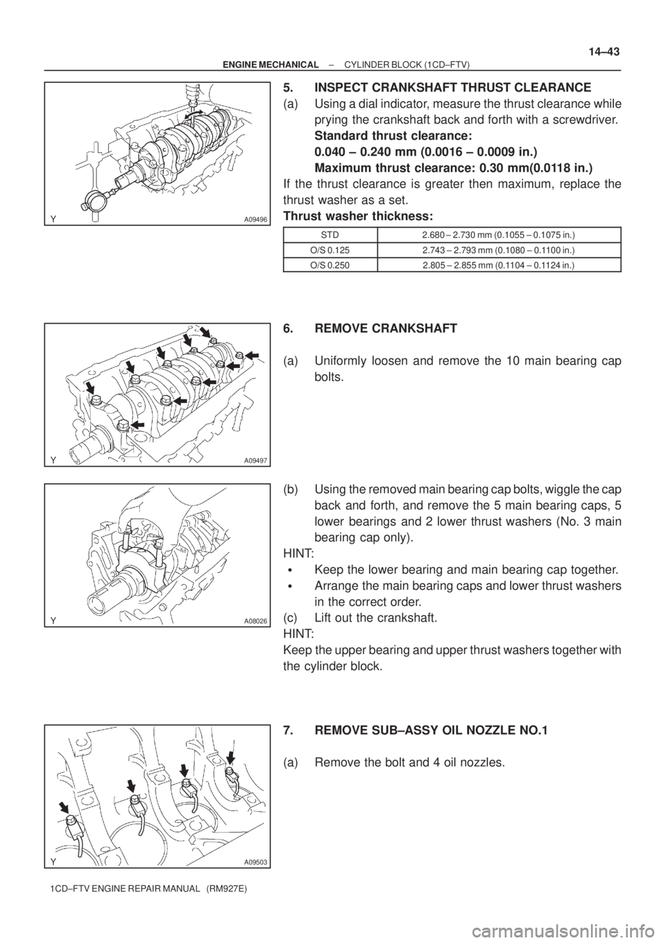
5. INSPECT CRANKSHAFT THRUST CLEARANCE
(a) Using a dial indicator, measure the thrust clearance while
prying the crankshaft back and forth with a screwdriver.
Standard thrust clearance:
0.040 ± 0.240 mm (0.0016 ± 0.0009 in.)
Maximum thrust clearance: 0.30 mm(0.0118 in.)
If the thrust clearance is greater then maximum, replace the
thrust washer as a set.
Thrust washer thickness:
STD2.680 ± 2.730 mm (0.1055 ± 0.1075 in.)
O/S 0.1252.743 ± 2.793 mm (0.1080 ± 0.1100 in.)
O/S 0.2502.805 ± 2.855 mm (0.1104 ± 0.1124 in.)
6. REMOVE CRANKSHAFT
(a) Uniformly loosen and remove the 10 main bearing cap
bolts.
(b) Using the removed main bearing cap bolts, wiggle the cap
back and forth, and remove the 5 main bearing caps, 5
lower bearings and 2 lower thrust washers (No. 3 main
bearing cap only).
HINT:
�Keep the lower bearing and main bearing cap together.
�Arrange the main bearing caps and lower thrust washers
in the correct order.
(c) Lift out the crankshaft.
HINT:
Keep the upper bearing and upper thrust washers together with
the cylinder block.
7. REMOVE SUB±ASSY OIL NOZZLE NO.1
(a) Remove the bolt and 4 oil nozzles.
Page 84 of 136
A09473
Hexagon
Wrench (6 mm)
A09457
A09502
A09501
14±44
± ENGINE MECHANICALCYLINDER BLOCK (1CD±FTV)
1CD±FTV ENGINE REPAIR MANUAL (RM927E)
8. REMOVE CYLINDER BLOCK OIL ORIFICE
(a) Using a hexagon wrench (6 mm), remove the oil orifice.
9. REMOVE PISTON RING SET
(a) Using a piston ring expander, remove the No. 1 piston
ring, No. 2 piston ring and oil ring.
NOTICE:
Make the expansion of the piston ring as small as neces-
sary.
(b) Remove the coil by hand.
HINT:
Arrange the piston rings in correct order.
10. REMOVE W/PIN PISTON SUB±ASSY
(a) Using a small screwdriver, pry off the snap rings from the
piston.
(b) Gradually heat the piston to approx. 60�C (140�F).
(c) Using a plastic±faced hammer and brass bar, lightly tap
out the piston pin and remove the connecting rod.
HINT:
�The piston and pin are a matched set.
�Arrange the pistons, pins, rings, connecting rods and
bearings in the correct order.
Page 91 of 136
A09497
A09500
± ENGINE MECHANICALCYLINDER BLOCK (1CD±FTV)
14±51
1CD±FTV ENGINE REPAIR MANUAL (RM927E)
(h) Apply a light coat of engine oil on the threads and under
the heads of the main bearing cap bolts.
(i) Install and uniformly tighten the 10 bolts of the main bear-
ing cap in several passes.
Torque: 115 N�m (1,173 kgf�cm, 85 ft�lbf)
NOTICE:
Do not turn the crankshaft.
(j) Remove the bearing cap.
(k) Measure the Plastigage at its widest point.
Standard oil clearance:
0.026 ± 0.044 mm (0.0010 ± 0.0017 in.)
Maximum oil Clearance: 0.10 mm (0.0039 in.)
If the oil clearance is greater then maximum, replace the bear-
ings. If necessary, replace the crankshaft.
Page 92 of 136

A09688
No.1No.2
No.3
No.4
No.5No.1No.2No.3 No.4No.5
Mark
1, 2 or 3
Mark
0, 1 or 2Mark
1, 2, 3, 4 or 5
14±52
± ENGINE MECHANICALCYLINDER BLOCK (1CD±FTV)
1CD±FTV ENGINE REPAIR MANUAL (RM927E)
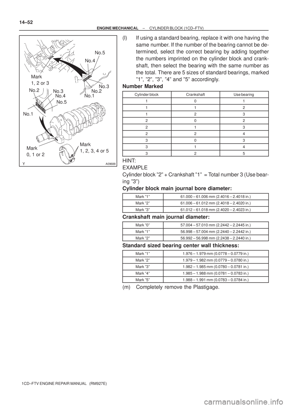
(l) If using a standard bearing, replace it with one having the
same number. If the number of the bearing cannot be de-
termined, select the correct bearing by adding together
the numbers imprinted on the cylinder block and crank-
shaft, then select the bearing with the same number as
the total. There are 5 sizes of standard bearings, marked
º1º, º2º, º3º, º4º and º5º accordingly.
Number Marked
Cylinder blockCrankshaftUse bearing
101
112
123
202
213
224
303
314
325
HINT:
EXAMPLE
Cylinder block º2º + Crankshaft º1º = Total number 3 (Use bear-
ing º3º)
Cylinder block main journal bore diameter:
Mark º1º61.000 ± 61.006 mm (2.4016 ± 2.4018 in.)
Mark º2º61.006 ± 61.012 mm (2.4018 ± 2.4020 in.)
Mark º3º61.012 ± 61.018 mm (2.4020 ± 2.4023 in.)
Crankshaft main journal diameter:
Mark º0º57.004 ± 57.010 mm (2.2442 ± 2.2445 in.)
Mark º1º56.998 ± 57.004 mm (2.2440 ± 2.2442 in.)
Mark º2º56.992 ± 56.998 mm (2.2438 ± 2.2440 in.)
Standard sized bearing center wall thickness:
Mark º1º1.976 ± 1.979 mm (0.0778 ± 0.0779 in.)
Mark º2º1.979 ± 1.982 mm (0.0779 ± 0.0780 in.)
Mark º3º1.982 ± 1.985 mm (0.0780 ± 0.0781 in.)
Mark º4º1.985 ± 1.988 mm (0.0781 ± 0.0783 in.)
Mark º5º1.988 ± 1.991 mm (0.0783 ± 0.0784 in.)
(m) Completely remove the Plastigage.
Page 103 of 136
1906G±02
A55610
A55611
A55612
A55613
Magnetic Finger
19±2
± STARTING & CHARGINGSTARTER ASSY(1.4KW) (1CD±FTV)
1CD±FTV ENGINE REPAIR MANUAL (RM927E)
OVERHAUL
1. REMOVE STARTER YOKE ASSY
(a) Remove the nut, and disconnect the lead wire from the
magnetic switch terminal.
(b) Remove the 2 through bolts.
(c) Pull out the yoke together with the armature from the mag-
netic switch.
2. REMOVE STARTER CLUTCH SUB±ASSY
(a) Remove the 2 bolts and drive housing.
(b) Remove the clutch from the drive housing.
(c) Using a magnetic finger, remove the ball from the clutch
shaft hole.
Page 104 of 136
A55614
A51226
A55615
A55616
± STARTING & CHARGINGSTARTER ASSY(1.4KW) (1CD±FTV)
19±3
1CD±FTV ENGINE REPAIR MANUAL (RM927E)
3. REMOVE STARTER BRUSH HOLDER ASSY
(a) Remove the 2 screws and end frame from the yoke.
(b) Using a screwdriver, hold the spring back disconnect the
brush from the brush holder. Disconnect the 4 brushers
and remove the brush holder.
4. REMOVE STARTER ARMATURE ASSY
(a) Remove the armature from the yoke.
5. INSPECT STARTER ARMATURE ASSY
(a) Using an ohmmeter, check that there is continuity be-
tween the segments of the commutator.
(b) Using an ohmmeter, check that there is no continuity be-
tween the commutator and armature coil core.