Page 39 of 136

A62448
Matchmarks
B08239
Approx. 38�
A62453
60�3 4 5
2
1 60�
A62454
Seal Width
0.1 ± 0.2 mmSeal
Packing
± INTAKETURBOCHARGER ASSEMBLY (1CD±FTV)
13±7
1CD±FTV ENGINE REPAIR MANUAL (RM927E)
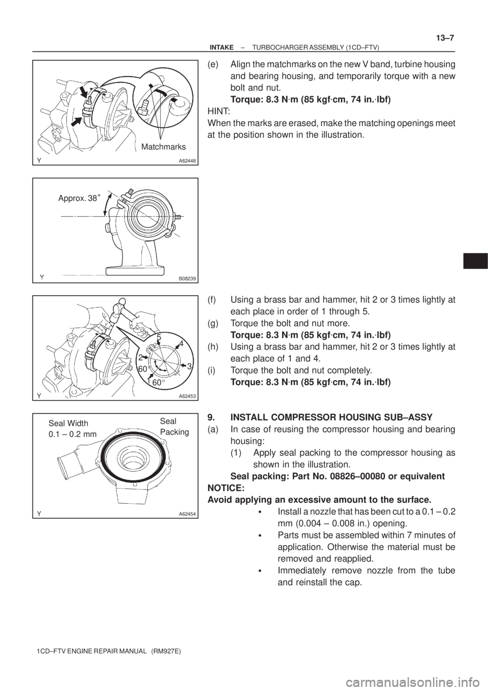
(e) Align the matchmarks on the new V band, turbine housing
and bearing housing, and temporarily torque with a new
bolt and nut.
Torque: 8.3 N�m (85 kgf�cm, 74 in.�lbf)
HINT:
When the marks are erased, make the matching openings meet
at the position shown in the illustration.
(f) Using a brass bar and hammer, hit 2 or 3 times lightly at
each place in order of 1 through 5.
(g) Torque the bolt and nut more.
Torque: 8.3 N�m (85 kgf�cm, 74 in.�lbf)
(h) Using a brass bar and hammer, hit 2 or 3 times lightly at
each place of 1 and 4.
(i) Torque the bolt and nut completely.
Torque: 8.3 N�m (85 kgf�cm, 74 in.�lbf)
9. INSTALL COMPRESSOR HOUSING SUB±ASSY
(a) In case of reusing the compressor housing and bearing
housing:
(1) Apply seal packing to the compressor housing as
shown in the illustration.
Seal packing: Part No. 08826±00080 or equivalent
NOTICE:
Avoid applying an excessive amount to the surface.
�Install a nozzle that has been cut to a 0.1 ± 0.2
mm (0.004 ± 0.008 in.) opening.
�Parts must be assembled within 7 minutes of
application. Otherwise the material must be
removed and reapplied.
�Immediately remove nozzle from the tube
and reinstall the cap.
Page 40 of 136

A62455
Matchmarks
A62456
Cut
Protractor
Steel Square49�
A62457
SST
13±8
± INTAKETURBOCHARGER ASSEMBLY (1CD±FTV)
1CD±FTV ENGINE REPAIR MANUAL (RM927E)
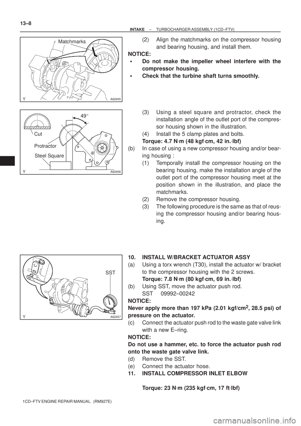
(2) Align the matchmarks on the compressor housing
and bearing housing, and install them.
NOTICE:
�Do not make the impeller wheel interfere with the
compressor housing.
�Check that the turbine shaft turns smoothly.
(3) Using a steel square and protractor, check the
installation angle of the outlet port of the compres-
sor housing shown in the illustration.
(4) Install the 5 clamp plates and bolts.
Torque: 4.7 N�m (48 kgf�cm, 42 in.�lbf)
(b) In case of using a new compressor housing and/or bear-
ing housing :
(1) Temporally install the compressor housing on the
bearing housing, make the installation angle of the
outlet port of the compressor housing meet at the
position shown in the illustration, and place the
matchmarks.
(2) Remove the compressor housing.
(3) The following procedure is the same as that of reus-
ing the compressor housing and/or bearing hous-
ing.
10. INSTALL W/BRACKET ACTUATOR ASSY
(a) Using a torx wrench (T30), install the actuator w/ bracket
to the compressor housing with the 2 screws.
Torque: 7.8 N�m (80 kgf�cm, 69 in.�lbf)
(b) Using SST, move the actuator push rod.
SST 09992±00242
NOTICE:
Never apply more than 197 kPa (2.01 kgf/cm
2, 28.5 psi) of
pressure on the actuator.
(c) Connect the actuator push rod to the waste gate valve link
with a new E±ring.
NOTICE:
Do not use a hammer, etc. to force the actuator push rod
onto the waste gate valve link.
(d) Remove the SST.
(e) Connect the actuator hose.
11. INSTALL COMPRESSOR INLET ELBOW
Torque: 23 N�m (235 kgf�cm, 17 ft�lbf)
Page 43 of 136
140L4±01
A56691
A62591
A56692
A56693
± ENGINE MECHANICALPARTIAL ENGINE ASSY (1CD±FTV)
14±3
1CD±FTV ENGINE REPAIR MANUAL (RM927E)
OVERHAUL
1. REMOVE OIL FILLER CAP SUB±ASSY
2. REMOVE NOZZLE HOLDER SEAL
(a) Using a screwdriver, pry out the 4 nozzle holder seals.
3. REMOVE CYLINDER HEAD COVER SUB±ASSY
(a) Remove the 10 bolts, cylinder head cover and gasket.
4. REMOVE NOZZLE LEAKAGE PIPE ASSY
(a) Using a hexagon wrench (6mm), remove 4 hollow screws.
(b) Remove the union bolt, nozzle leakage pipe and 5 gas-
kets from the cylinder head and injector.
5. REMOVE NOZZLE HOLDER CLAMP
(a) Remove the 4 bolts, 4 washers and 4 nozzle holder
clamps.
Page 44 of 136
A56694
A62592
SST
A57095
Hexagon
Wrench
(8mm)
SST
A57096
14±4
± ENGINE MECHANICALPARTIAL ENGINE ASSY (1CD±FTV)
1CD±FTV ENGINE REPAIR MANUAL (RM927E)
6. REMOVE INJECTOR ASSY
(a) Remove the 4 injectors from the cylinder head.
HINT:
Arrange the injectors in correct order.
7. REMOVE CAMSHAFT TIMING PULLEY
(a) Using SST, remove the pulley bolt.
SST 09960±10010 (09962±01000, 09963±01000)
8. REMOVE TIMING BELT IDLER SUB±ASSY NO.1
(a) Using hexagon wrench (8mm), remove the idler pulley
shaft, idler pulley and plate washer.
9. REMOVE TIMING BELT IDLER SUB±ASSY NO.2
10. REMOVE CRANKSHAFT TIMING PULLEY
(a) If the pulley cannot be removed by hand, use SST to re-
move the timing pulley.
SST 09950±50013 (09951±05010, 09952±05010,
09953±05010, 09953±05020, 09954±05021)
Page 45 of 136
A57097
A57098
A09650
1 3
24
576
8
9
10 11
12
13 14
15
A09624
± ENGINE MECHANICALPARTIAL ENGINE ASSY (1CD±FTV)
14±5
1CD±FTV ENGINE REPAIR MANUAL (RM927E)
11. REMOVE CAMSHAFT OIL SEAL RETAINER
(a) Remove the 4 bolts.
(b) Using a screwdriver, remove the oil seal retainer by prying
the portions between the oil seal retainer and camshaft
bearing cap.
12. REMOVE WATER PUMP ASSY
(a) Remove the 7 bolts, water pump and gasket.
13. REMOVE CAMSHAFT SUB±ASSY, NO.2
(a) Uniformly loosen and remove the 15 bearing cap bolts in
several passes in the sequence shown.
(b) Remove the 5 bearing caps.
(c) Remove the camshaft No. 2.
14. REMOVE CAMSHAFT SUB±ASSY, NO.1
(a) Remove the camshaft from the cylinder head.
(b) Remove the camshaft carrier from the cylinder head.
Page 46 of 136

A09566
2
1 3
45
67 8
9
14 15 16
17 1211 1013
18
A09563
Pry
A56695
SSTSST
B08601
A56696
14±6
± ENGINE MECHANICALPARTIAL ENGINE ASSY (1CD±FTV)
1CD±FTV ENGINE REPAIR MANUAL (RM927E)
15. REMOVE CYLINDER HEAD SUB±ASSY
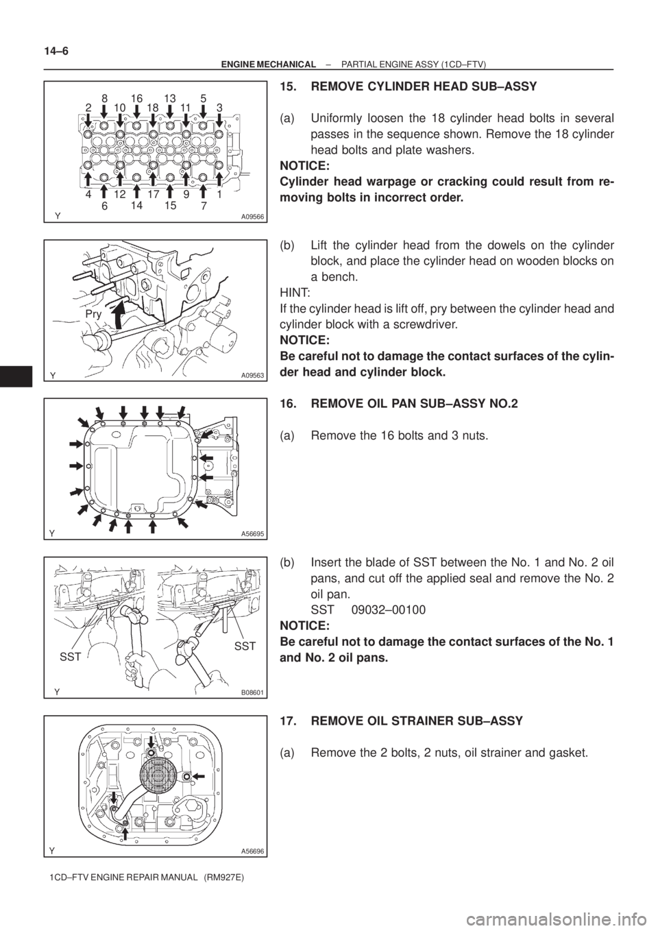
(a) Uniformly loosen the 18 cylinder head bolts in several
passes in the sequence shown. Remove the 18 cylinder
head bolts and plate washers.
NOTICE:
Cylinder head warpage or cracking could result from re-
moving bolts in incorrect order.
(b) Lift the cylinder head from the dowels on the cylinder
block, and place the cylinder head on wooden blocks on
a bench.
HINT:
If the cylinder head is lift off, pry between the cylinder head and
cylinder block with a screwdriver.
NOTICE:
Be careful not to damage the contact surfaces of the cylin-
der head and cylinder block.
16. REMOVE OIL PAN SUB±ASSY NO.2
(a) Remove the 16 bolts and 3 nuts.
(b) Insert the blade of SST between the No. 1 and No. 2 oil
pans, and cut off the applied seal and remove the No. 2
oil pan.
SST 09032±00100
NOTICE:
Be careful not to damage the contact surfaces of the No. 1
and No. 2 oil pans.
17. REMOVE OIL STRAINER SUB±ASSY
(a) Remove the 2 bolts, 2 nuts, oil strainer and gasket.
Page 47 of 136
A56697
A56698
A56699
A09518
A09519
Hexagon
Wrench
(8mm)
± ENGINE MECHANICALPARTIAL ENGINE ASSY (1CD±FTV)
14±7
1CD±FTV ENGINE REPAIR MANUAL (RM927E)
18. REMOVE OIL PAN SUB±ASSY
(a) Remove the 19 bolts and 3 nuts.
(b) Using a screwdriver, remove the oil pan by prying the por-
tions between the cylinder block and No. 1 oil pan.
NOTICE:
Be careful not to damage the contact surfaces of the cylin-
der block and No. 1 oil pan.
19. REMOVE OIL PUMP ASSY
(a) Remove the 9 bolts.
(b) Remove the oil pump by prying a screwdriver between the
oil pump and main bearing cap.
(c) Remove the gasket.
20. REMOVE ENGINE REAR OIL SEAL RETAINER
(a) Remove the 6 bolts.
(b) Using a screwdriver, remove the oil seal retainer by prying
the portions between the oil seal retainer and main bear-
ing cap.
21. REMOVE OIL CHECK VALVE SUB±ASSY
(a) Using hexagon wrench (8mm), remove the pressure
valve and gasket.
Page 48 of 136
A09619
SST
A09620
B07976
A56700
SST
14±8
± ENGINE MECHANICALPARTIAL ENGINE ASSY (1CD±FTV)
1CD±FTV ENGINE REPAIR MANUAL (RM927E)
22. REMOVE CYLINDER BLOCK WATER DRAIN COCK SUB±ASSY
23. REMOVE CAMSHAFT OIL SEAL
(a) Using a screwdriver and a hammer, tap out the oil seal.
24. INSTALL CAMSHAFT OIL SEAL
(a) Using SST and a hammer, tap in a new oil seal until its sur-
face is flush with the camshaft oil seal retainer edge.
SST 09223±46011
25. REMOVE CRANKSHAFT SEAL
(a) Using a screwdriver and a hammer, tap out the oil seal.
26. INSTALL CRANKSHAFT SEAL
(a) Using SST and a hammer, tap in a new oil seal until its sur-
face is flush with the oil pump edge.
SST 09316±60011 (09316±00011, 09316±00021)