Page 51 of 136

14±11
1CD±FTV ENGINE REPAIR MANUAL (RM927E)
(c) Pour in 0.5 cm3 (0.03 cu in.) or more of")
B08024
A57099
A56702
A56703
Seal Width
4 ± 7 mm AB
B A
± ENGINE MECHANICALPARTIAL ENGINE ASSY (1CD±FTV)
14±11
1CD±FTV ENGINE REPAIR MANUAL (RM927E)
(c) Pour in 0.5 cm3 (0.03 cu in.) or more of engine oil into the
bushing of the cylinder block.
(d) Apply engine oil to the cylinder block side where it con-
tacts with the oil pump driven rotor.
(e) Install the oil pump with the 9 bolts.
Torque: 31 N�m (320 kgf�cm, 23 ft�lbf)
(f) Measure the oil pump rotating torque
(1) Check that the pump rotates smoothly without ab-
normal noise.
(2) Using a torque wrench, check the pump rotating
torque.
Rotating torque: 3.0 N�m (30 kgf�cm, 26 in.�lbf) or less
34. INSTALL OIL PAN SUB±ASSY
(a) Apply seal packing to the No. 1 oil pan as shown in the
illustration.
Seal packing: Part No. 08826±00080 or equivalent
NOTICE:
�Install a nozzle that has been cut to a 4 ± 7 mm (0.16
± 0.28 in.) opening.
�Parts must be assembled within 15 minutes of ap-
plication. Otherwise the material must be removed
and reapplied.
�Immediately remove nozzle from the tube and rein-
stall the cap.
(b) Install the oil pan with 19 bolts and 3 nuts.
Torque:
11 N�m (112 kgf�cm, 8 ft�lbf) for 10 mm head bolt and
nut
21 N�m (210 kgf�cm, 15 ft�lbf) for 12 mm head bolt
42 N�m (429 kgf�cm, 31 ft�lbf) for 14 mm head bolt
Page 52 of 136

1CD±FTV ENGINE REPAIR MANUAL (RM927E")
A56696
A56704
Seal Width
4 ± 7 mmBA
A
B
A56706
Front
Measuring Point
A57100
Measuring Tip
Protrusion 14±12
± ENGINE MECHANICALPARTIAL ENGINE ASSY (1CD±FTV)
1CD±FTV ENGINE REPAIR MANUAL (RM927E)
35. INSTALL OIL STRAINER SUB±ASSY
(a) Install a new gasket and the oil strainer with the 2 bolts
and 2 nuts.
Torque:
21 N�m (210 kgf�cm, 15 ft�lbf) for bolt
13 N�m (135 kgf�cm, 10 ft�lbf) for nut
36. INSTALL OIL PAN SUB±ASSY NO.2
(a) Apply a seal packing to the oil pan as shown in the illustra-
tion.
Seal packing: Part No. 08826±00080 or equivalent
NOTICE:
�Install a nozzle that has been cut to a 4 ± 7 mm (0.16
± 0.28 in.) opening.
�Parts must be assembled within 15 minutes of ap-
plication. Otherwise the material must be removed
and reapplied.
�Immediately remove nozzle from the tube and rein-
stall the cap.
(b) Install the oil pan with 16 bolts and 3 nuts. Uniformly tight-
en the bolts and nuts in several passes.
Torque: 12 N�m (120 kgf�cm, 9 ft�lbf)
37. INSTALL CYLINDER HEAD SUB±ASSY
(a) Check piston protrusions for each cylinder.
(1) Find where the piston head protrudes most by slow-
ly turning the crankshaft clockwise and counter-
clockwise.
(2) Measure each cylinder at 2 places as shown in the
illustration, marking a total of 8 measurements.
(3) For the piston protrusion valve of each cylinder, use
the average of the 2 measurements of each cylin-
der.
Protrusion: 0.165 ± 0.425 mm (0.0065 ± 0.0168 in.)
Page 53 of 136

10 11
12 1314
1516 17(B)
(A) (A) (A) (A)(A) (A)
(A)
(B) (B) (B) (B)
(B) (B) (B) (B) (B)
± ENGINE MECHANICALPARTIAL ENGINE ASSY (1CD±FTV)
1")
A
B
C
D
E
A09570
Front
A56055
A09564
1
18 2 3
4 56
78 9 (A)
10 11
12 1314
1516 17(B)
(A) (A) (A) (A)(A) (A)
(A)
(B) (B) (B) (B)
(B) (B) (B) (B) (B)
± ENGINE MECHANICALPARTIAL ENGINE ASSY (1CD±FTV)
14±13
1CD±FTV ENGINE REPAIR MANUAL (RM927E)
(b) Select a new cylinder head gasket.
HINT:
There are 5 sizes of new cylinder head gaskets, marked ºAº,
ºBº, ºCº, ºDº, or ºEº according.
New installed cylinder head gasket thickness:
A0.85 ± 0.95 mm (0.0335 ± 0.0374 in.)
B0.90 ± 1.00 mm (0.0354 ± 0.0394 in.)
C0.95 ± 1.05 mm (0.0374 ± 0.0413 in.)
D1.00 ± 1.10 mm (0.0394 ± 0.0433 in.)
E1.05 ± 1.15 mm (0.0413 ± 0.0453 in.)
(1) Select the largest piston protrusion value from the
measurements made, then select a new appropri-
ate gasket according to the table below.
Piston protrusion mm (in.)Gasket size
0.165 ± 0.220 (0.0065 ± 0.0087)Use A
0.220 ± 0.270 (0.0087 ± 0.0106)Use B
0.270 ± 0.320 (0.0106 ± 0.0126)Use C
0.320 ± 0.370 (0.0126 ± 0.0146)Use D
0.370 ± 0.425 (0.0146 ± 0.0167)Use E
(c) Place a new cylinder head gasket in position on the cylin-
der block.
NOTICE:
Be careful of the installation direction.
(d) Place the cylinder head in position on the cylinder head
gasket.
(e) Install the cylinder head bolts.
HINT:
The cylinder head bolts are tightened in 4 progressive steps
(steps (3), (5), (6) and (7)).
(1) Apply a light coat of engine oil on the threads and
under the heads of the cylinder head bolts and plate
washers.
(2) Install the plate washer to the cylinder head bolt.
(3) Install and uniformly tighten the 18 cylinder head
bolts and plate washers in several passes in the se-
quence shown.
Torque: 45 N�m (460 kgf�cm, 33 ft�lbf)
HINT:
Each bolt length is indicated in the illustration.
Bolt length:
(A)160 mm (6.30 in.)
(B)104 mm (4.09 in.)
If any of the cylinder head bolt does not meet the torque specifi-
cation, replace the cylinder head bolts.
Page 62 of 136
140L5±01
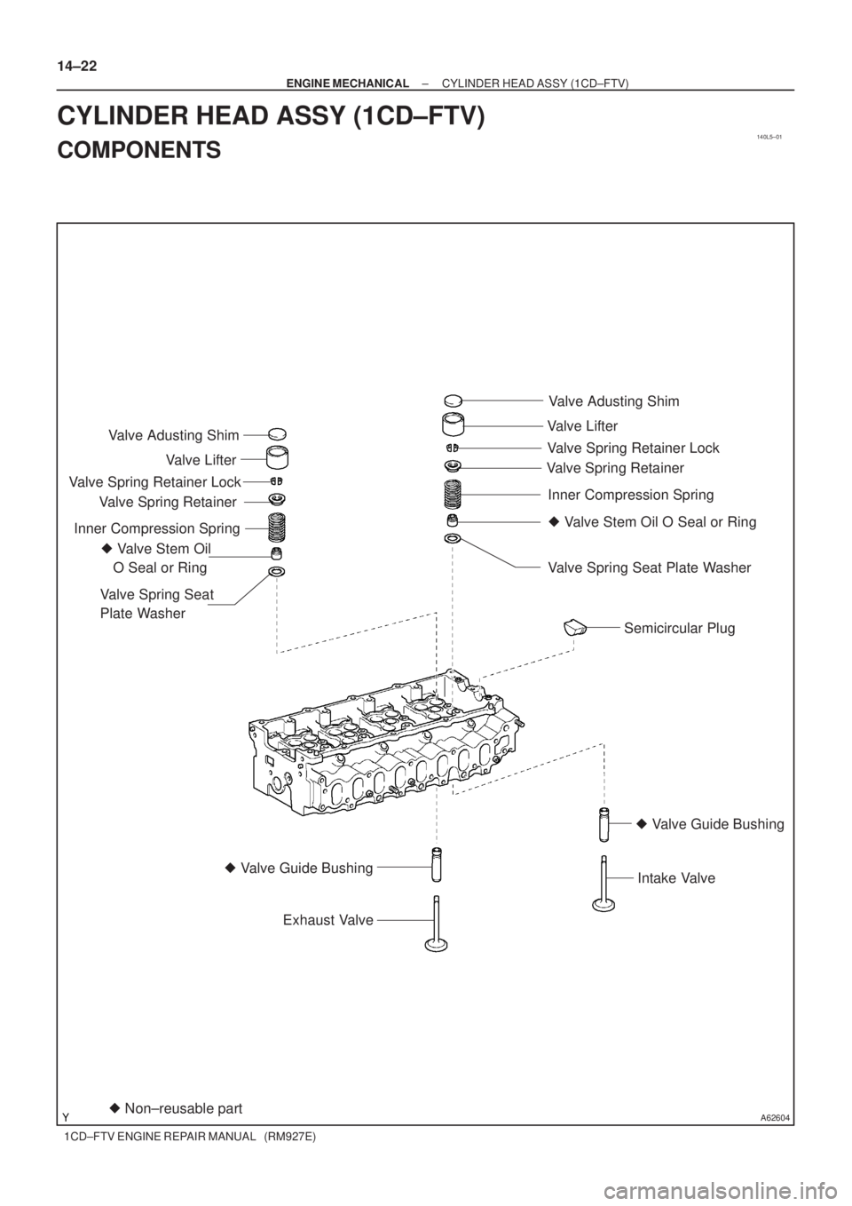
A62604� Non±reusable part � Valve Stem Oil
O Seal or RingValve Adusting Shim
Valve Lifter
Valve Spring Retainer
Valve Spring Retainer Lock
Inner Compression Spring
Valve Spring Seat
Plate Washer
� Valve Guide Bushing
Exhaust Valve
Semicircular Plug
� Valve Stem Oil O Seal or Ring Valve Adusting Shim
Valve Lifter
Valve Spring RetainerValve Spring Retainer Lock
Inner Compression Spring
Valve Spring Seat Plate Washer
� Valve Guide Bushing
Intake Valve
14±22
± ENGINE MECHANICALCYLINDER HEAD ASSY (1CD±FTV)
1CD±FTV ENGINE REPAIR MANUAL (RM927E)
CYLINDER HEAD ASSY (1CD±FTV)
COMPONENTS
Page 64 of 136
A62595
A56049
Cylinder Block Side
Intake Manifold Side
Exhaust Manifold Side
A09534
14±24
± ENGINE MECHANICALCYLINDER HEAD ASSY (1CD±FTV)
1CD±FTV ENGINE REPAIR MANUAL (RM927E)
6. REMOVE SEMICIRCULAR PLUG
7. REMOVE W/HEAD TAPER SCREW PLUG NO.1
(a) Using a hexagon wrench (6mm), remove the 3 plugs.
SST 99999±70037
8. INSPECT CYLINDER HEAD FOR FLATNESS
(a) Using a precision straight edge and feeler gauge, mea-
sure the surfaces contacting the cylinder block and the
manifolds for warpage.
Maximum warpage:
Cylinder block side0.08mm (0.0031in.)
Intake manifold side0.20mm (0.0079in.)
Exhaust manifold side0.20mm (0.0079in.)
9. INSPECT CYLINDER HEAD FOR CRACKS
(a) Using dye penetrant, check the intake ports, exhaust
ports and cylinder block contact surface for cracks.
Page 72 of 136

1CD±FTV ENGINE REPAIR MANUAL (RM927E)
23. INSPECT CAMSHAFT
(a) Inspect the circle runout.
(1)")
A09550
A09551
A09552
A09546
Plastigage
A09557
14±32
± ENGINE MECHANICALCYLINDER HEAD ASSY (1CD±FTV)
1CD±FTV ENGINE REPAIR MANUAL (RM927E)
23. INSPECT CAMSHAFT
(a) Inspect the circle runout.
(1) Place the camshaft on V±blocks.
(2) Using a dial indicator, measure the circle runout at
the center journal.
Maximum circle runout: 0.06 mm (0.0024 in.)
If the circle runout is greater then maximum, replace the cam-
shaft.
(b) Using a micrometer, measure the cam lobe height.
Standard cam lobe height:
Intake46.57 ± 46.67 mm (1.8335 ± 1.8374 in.)
Exhaust47.52 ± 47.62 mm (1.8709 ± 1.8748 in.)
Minimum cam lobe height:
Intake46.10 mm (1.8150 in.)
Exhaust47.05 mm (1.8524 in.)
If the cam lobe height is less than minimum, replace the cam-
shaft.
(c) Using a micrometer, measure the journal diameter.
Journal diameter:
26.969 ± 26.985 mm (1.0618 ± 1.0624 in.)
If the journal diameter is not as specified, check the oil clear-
ance.
24. INSPECT CAMSHAFT OIL CLEARANCE
(a) Clean the bearing caps and camshaft carrier.
(b) Check the bearings for flaking and scoring.
If the bearings are damaged, replace the bearing caps, cam-
shaft carrier and cylinder head as a set.
(c) Place the camshaft carrier and camshafts on the cylinder
head.
(d) Lay a strip of Plastigage across each of the camshaft jour-
nals.
(e) Install the bearing caps.
Torque: 20 N�m (200 kgf�cm, 15 ft�lbf)
NOTICE:
Do not turn the camshaft.
(f) Remove the bearing caps.
Page 74 of 136
A56680
Intake Side:Cylinder Block Side:
Front Side: Rear Side:
1.5 mm 14±34
± ENGINE MECHANICALCYLINDER HEAD ASSY (1CD±FTV)
1CD±FTV ENGINE REPAIR MANUAL (RM927E)
27. INSTALL TIGHT PLUG
(a) Apply adhesive around tight plugs.
Adhesive: Part No.08833 ± 00070, THREE BOND 1324
or equivalent
(b) Using SST, tap in the tight plugs as shown in the illustra-
tion.
SST 09950±60010 (09951±00210), 09950±70010
(09951±07100)
Page 79 of 136
140L6±01
A62605
No.1 Piston Ring
No.2 Piston Ring
Oil Ring
Connecting Rod
Connecting Rod
Bearing Connecting
Rod Cap Cylinder Block
Upper Crankshaft
Thrust Washer Crankshaft
Lower Crankshaft
Thrust Washer
Main Bearing CapLower Main Bearing
Upper Main Bearing Coil
� Non±reusable part
N´m (kgf´cm, ft´lbf)
Piston
: Specified torque
Connecting Rod
Bearing
See Page 14±40
1st 30 (306, 22)
2nd Turn 90
�
� Snap Ring
� Snap Ring
Cylinder Block
Oil Orifice
Sub±assy
Oil Nozzle No.1
115 (1,173, 85)
Piston Pin
9.0 (92, 78 in.´lbf)
7.4 (76, 67 in.´lbf)
±
ENGINE MECHANICAL CYLINDER BLOCK (1CD±FTV)
14±39
1CD±FTV ENGINE REPAIR MANUAL (RM927E)
CYLINDER BLOCK (1CD±FTV)
COMPONENTS

1CD±FTV ENGINE REPAIR MANUAL (RM927E)
6. REMOVE SEMICIRC")

1CD±FTV ENGINE REPAIR MANUAL (RM927E)
27. INSTALL TIGHT PLUG
(a) Apply")
