Page 20 of 136
0214U±01
02±6
± PREPARATIONSTARTING & CHARGING
1CD±FTV ENGINE REPAIR MANUAL (RM927E)
STARTING & CHARGING
PREPARATION
SST
09820±63020Alternator Pulley Wrench SetGENERATOR
ASSY(130A)(1CD±FTV)
09950±40011Puller B SetGENERATOR
ASSY(130A)(1CD±FTV)
(09951±04020)Hanger 200GENERATOR
ASSY(130A)(1CD±FTV)
(09952±04010)Slide ArmGENERATOR
ASSY(130A)(1CD±FTV)
(09953±04020)Center Bolt 150GENERATOR
ASSY(130A)(1CD±FTV)
(09954±04010)Arm 25GENERATOR
ASSY(130A)(1CD±FTV)
(09955±04071)Claw No.7GENERATOR
ASSY(130A)(1CD±FTV)
(09958±04011)HolderGENERATOR
ASSY(130A)(1CD±FTV)
09950±60010Replacer SetSTARTER ASSY(2.0KW)(1CD±FTV)
(09951±00340)Replacer 34STARTER ASSY(2.0KW)(1CD±FTV)
Recomended Tools
09082±00040TOYOTA Electrical TesterSTARTER ASSY(1.4KW)(1CD±FTV)
STARTER ASSY(2.2KW)(1CD±FTV)
GENERATOR
ASSY(130A)(1CD±FTV)
(09083±00150)Test Lead SetSTARTER ASSY(1.4KW)(1CD±FTV)
STARTER ASSY(2.2KW)(1CD±FTV)
GENERATOR ASSY(90A)(1CD±FTV)
GENERATOR
ASSY(130A)(1CD±FTV)
Page 21 of 136
± PREPARATIONSTARTING & CHARGING
02±7
1CD±FTV ENGINE REPAIR MANUAL (RM927E)
(09083±00350)AC/DC 400 A ProbeSTARTER ASSY(2.2KW)(1CD±FTV)
Equipment
V±block
Feeler gauge
Ohmmeter
Torque wrench
Vernier calipers
Dial indicator with magnetic base
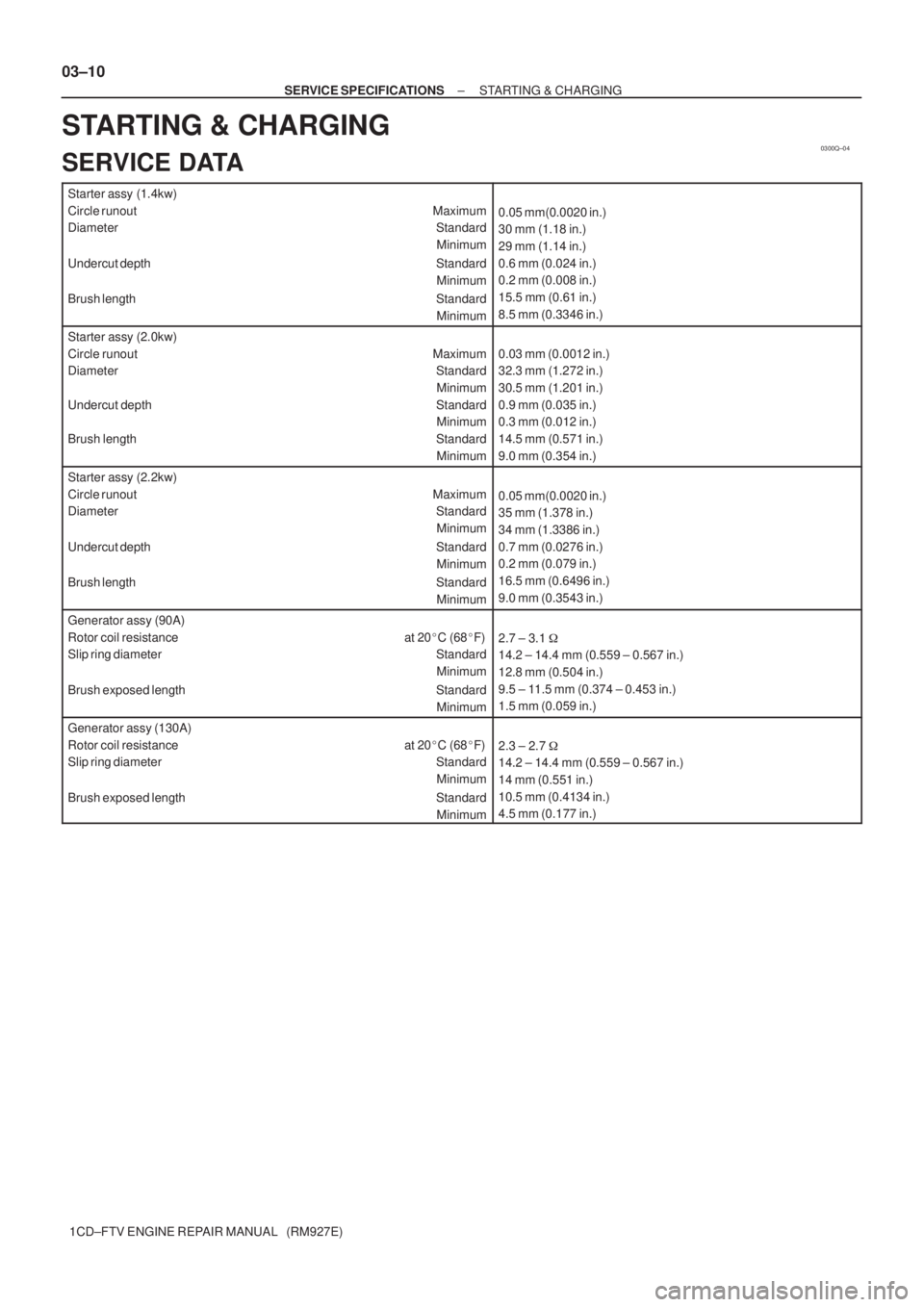
Page 31 of 136

0300Q±04
03±10
± SERVICE SPECIFICATIONSSTARTING & CHARGING
1CD±FTV ENGINE REPAIR MANUAL (RM927E)
STARTING & CHARGING
SERVICE DATA
Starter assy (1.4kw)
Circle runout Maximum
Diameter Standard
Minimum
Undercut depth Standard
Minimum
Brush length Standard
Minimum
0.05 mm(0.0020 in.)
30 mm (1.18 in.)
29 mm (1.14 in.)
0.6 mm (0.024 in.)
0.2 mm (0.008 in.)
15.5 mm (0.61 in.)
8.5 mm (0.3346 in.)
Starter assy (2.0kw)
Circle runout Maximum
Diameter Standard
Minimum
Undercut depth Standard
Minimum
Brush length Standard
Minimum
0.03 mm (0.0012 in.)
32.3 mm (1.272 in.)
30.5 mm (1.201 in.)
0.9 mm (0.035 in.)
0.3 mm (0.012 in.)
14.5 mm (0.571 in.)
9.0 mm (0.354 in.)
Starter assy (2.2kw)
Circle runout Maximum
Diameter Standard
Minimum
Undercut depth Standard
Minimum
Brush length Standard
Minimum
0.05 mm(0.0020 in.)
35 mm (1.378 in.)
34 mm (1.3386 in.)
0.7 mm (0.0276 in.)
0.2 mm (0.079 in.)
16.5 mm (0.6496 in.)
9.0 mm (0.3543 in.)
Generator assy (90A)
Rotor coil resistance at 20�C (68�F)
Slip ring diameter Standard
Minimum
Brush exposed length Standard
Minimum
2.7 ± 3.1 �
14.2 ± 14.4 mm (0.559 ± 0.567 in.)
12.8 mm (0.504 in.)
9.5 ± 11.5 mm (0.374 ± 0.453 in.)
1.5 mm (0.059 in.)
Generator assy (130A)
Rotor coil resistance at 20�C (68�F)
Slip ring diameter Standard
Minimum
Brush exposed length Standard
Minimum
2.3 ± 2.7 �
14.2 ± 14.4 mm (0.559 ± 0.567 in.)
14 mm (0.551 in.)
10.5 mm (0.4134 in.)
4.5 mm (0.177 in.)
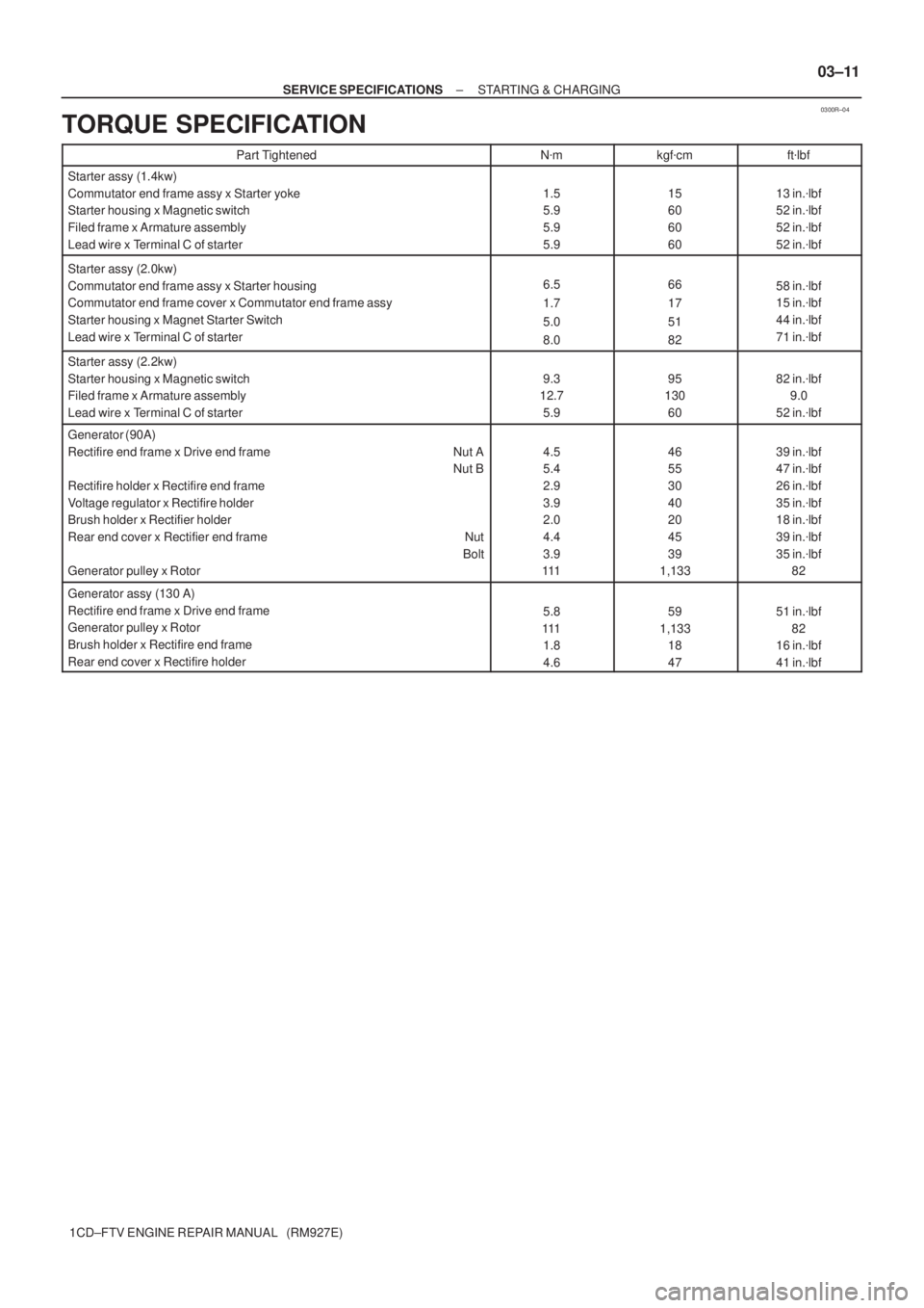
Page 32 of 136

0300R±04
± SERVICE SPECIFICATIONSSTARTING & CHARGING
03±11
1CD±FTV ENGINE REPAIR MANUAL (RM927E)
TORQUE SPECIFICATION
Part TightenedN�mkgf�cmft�lbf
Starter assy (1.4kw)
Commutator end frame assy x Starter yoke
Starter housing x Magnetic switch
Filed frame x Armature assembly
Lead wire x Terminal C of starter
1.5
5.9
5.9
5.915
60
60
6013 in.�lbf
52 in.�lbf
52 in.�lbf
52 in.�lbf
Starter assy (2.0kw)
Commutator end frame assy x Starter housing
Commutator end frame cover x Commutator end frame assy
Starter housing x Magnet Starter Switch
Lead wire x Terminal C of starter
6.5
1.7
5.0
8.066
17
51
8258 in.�lbf
15 in.�lbf
44 in.�lbf
71 in.�lbf
Starter assy (2.2kw)
Starter housing x Magnetic switch
Filed frame x Armature assembly
Lead wire x Terminal C of starter
9.3
12.7
5.995
130
6082 in.�lbf
9.0
52 in.�lbf
Generator (90A)
Rectifire end frame x Drive end frame Nut A
Nut B
Rectifire holder x Rectifire end frame
Voltage regulator x Rectifire holder
Brush holder x Rectifier holder
Rear end cover x Rectifier end frame Nut
Bolt
Generator pulley x Rotor
4.5
5.4
2.9
3.9
2.0
4.4
3.9
11146
55
30
40
20
45
39
1,13339 in.�lbf
47 in.�lbf
26 in.�lbf
35 in.�lbf
18 in.�lbf
39 in.�lbf
35 in.�lbf
82
Generator assy (130 A)
Rectifire end frame x Drive end frame
Generator pulley x Rotor
Brush holder x Rectifire end frame
Rear end cover x Rectifire holder
5.8
111
1.8
4.659
1,133
18
4751 in.�lbf
82
16 in.�lbf
41 in.�lbf
Page 102 of 136
190AE±01
A62712
Starter Armature Assy
Starter Yoke Assy
Starter Brush Holder Assy
Rear End Frame Cover
Drive Housing
Starter Clutch Sub±Assy Ball
Spring
Magnetic Switch
N´m (kgf´cm, ft´lbf)
: Specified torque
5.9 (60, 52 in.´lbf)
5.9 (60, 52 in.´lbf)
5.9 (60, 52 in.´lbf)
± STARTING & CHARGINGSTARTER ASSY(1.4KW) (1CD±FTV)
19±1
1CD±FTV ENGINE REPAIR MANUAL (RM927E)
STARTER ASSY(1.4KW) (1CD±FTV)
COMPONENTS
Page 103 of 136
1906G±02
A55610
A55611
A55612
A55613
Magnetic Finger
19±2
± STARTING & CHARGINGSTARTER ASSY(1.4KW) (1CD±FTV)
1CD±FTV ENGINE REPAIR MANUAL (RM927E)
OVERHAUL
1. REMOVE STARTER YOKE ASSY
(a) Remove the nut, and disconnect the lead wire from the
magnetic switch terminal.
(b) Remove the 2 through bolts.
(c) Pull out the yoke together with the armature from the mag-
netic switch.
2. REMOVE STARTER CLUTCH SUB±ASSY
(a) Remove the 2 bolts and drive housing.
(b) Remove the clutch from the drive housing.
(c) Using a magnetic finger, remove the ball from the clutch
shaft hole.
Page 104 of 136
A55614
A51226
A55615
A55616
± STARTING & CHARGINGSTARTER ASSY(1.4KW) (1CD±FTV)
19±3
1CD±FTV ENGINE REPAIR MANUAL (RM927E)
3. REMOVE STARTER BRUSH HOLDER ASSY
(a) Remove the 2 screws and end frame from the yoke.
(b) Using a screwdriver, hold the spring back disconnect the
brush from the brush holder. Disconnect the 4 brushers
and remove the brush holder.
4. REMOVE STARTER ARMATURE ASSY
(a) Remove the armature from the yoke.
5. INSPECT STARTER ARMATURE ASSY
(a) Using an ohmmeter, check that there is continuity be-
tween the segments of the commutator.
(b) Using an ohmmeter, check that there is no continuity be-
tween the commutator and armature coil core.
Page 105 of 136
A55617
A55618
A51188
A55619
A55620
19±4
± STARTING & CHARGINGSTARTER ASSY(1.4KW) (1CD±FTV)
1CD±FTV ENGINE REPAIR MANUAL (RM927E)
(c) Place the commutator on V±blocks.
(d) Using a dial gauge, measure the circle runout.
Maximum circle runout: 0.05 mm (0.002 in.)
(e) Using vernier calipers, measure the commutator diame-
ter.
Standard diameter: 30 mm (1.1811 in.)
Minimum diameter: 29 mm (1.1417 in.)
(f) Check that the undercut depth is clean and free of foreign
materials. Smooth out the edge.
Standard undercut depth: 0.6 mm (0.024 in.)
Minimum undercut depth: 0.2 mm (0.008 in.)
6. INSPECT STARTER YOKE ASSY
(a) Using an ohmmeter, check that there is continuity be-
tween the lead wire and field coil brush lead.
(b) Using an ohmmeter, check that there is no continuity be-
tween the field coil brush lead and yoke.