2004 SUBARU IMPREZA WRX light
[x] Cancel search: lightPage 271 of 491
7-2
Starting and operating
Starting and operatingFuel
Use of a fuel which is low in quality or use of an
inappropriate fuel additive may cause engine
damage.
! Fuel requirements
! 2.5 Liter models
The 2.5 Liter engine is designed to operate using un-
leaded gasoline with an octane rating of 87 AKI or
higher. ! 2.0 Liter (turbo) models
The 2.0 Liter turbo engine is designed to operate using
premium unleaded gasoline with an octane rating of
91 AKI or higher. If premium unleaded gasoline is not
available, regular unleaded gasoline with an octane
rating of 87 AKI or higher may be temporarily used.
For optimum engine performance and driveability, it is
recommended that you use premium grade unleaded
gasoline. !
2.5 Liter (turbo) model
The 2.5 Liter turbo engine is designed to operate using
super-premium unleaded gasoline with an octane rat-
ing of 93 AKI or higher. If super-premium unleaded
gasoline with an octane rating of 93 AKI or higher is
not available, premium unleaded gasoline with an oc-
tane rating of 91 AKI or higher can be used. For opti-
mum engine performance and driveability, it is recom-
mended that you use super-premium grade unleaded
gasoline with an octane rating of 93 AKI or higher. ! Fuel octane rating
This octane rating is the average of the Research Oc-
tane and Motor Octane numbers and is commonly re-
ferred to as the Anti Knock Index (AKI).
Using a gasoline with a lower octane rating can cause
persistent and heavy knocking, which can damage the
engine. Do not be concerned if your vehicle some-
times knocks lightly when you drive up a hill or when
you accelerate. See your dealer or a qualified service
technician if you use a fuel with the specified octane
rating and your vehicle knocks heavily or persistently. ! Unleaded gasoline
The neck of the fuel filler pipe is designed to accept
only an unleaded gasoline filler nozzle. Under no cir-
cumstances should leaded gasoline be used because
it will damage the emission control system and may
Page 274 of 491
7-5
Starting and operating
– CONTINUED –
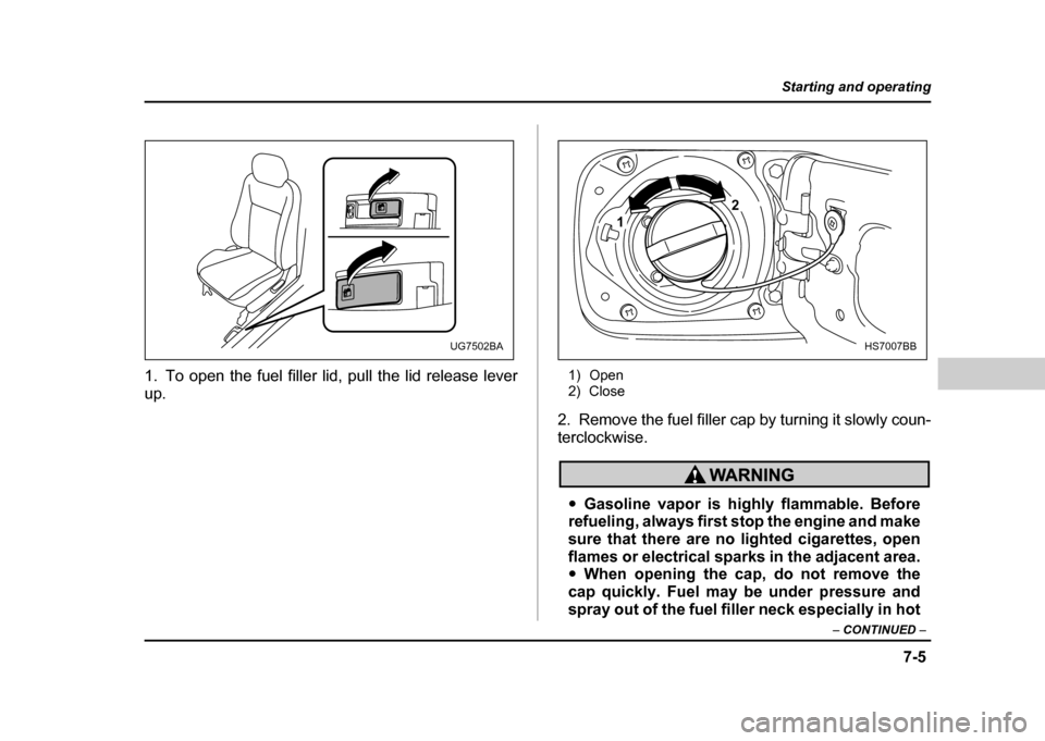
1. To open the fuel filler lid, pull the lid release lever
up. 1) Open
2) Close
2. Remove the fuel filler cap by turning it slowly coun-
terclockwise.
" Gasoline vapor is highly flammable. Before
refueling, always first stop the engine and make
sure that there are no lighted cigarettes, open
flames or electrical sparks in the adjacent area." When opening the cap, do not remove the
cap quickly. Fuel may be under pressure and
spray out of the fuel filler neck especially in hot
UG7502BA
1 2
HS7007BB
Page 275 of 491
7-6
Starting and operating
weather, which may cause injury.
3. Stop filling the tank after the fuel filler pump auto-
matically stops. Do not add any more fuel.
4. Put the cap back on, turn it clockwise until you hear
a clicking noise. Be certain not to catch the tether un-
der the cap while tightening.
5. Close the fuel filler lid completely.
If you spill any fuel on the painted surface, rinse it off
immediately. Otherwise, the painted surface could be
damaged.
NOTE
If the fuel filler cap is not tightened until it clicks or
if the tether is caught under the cap, the CHECK
ENGINE warning light may come on. Refer to the
“Warning and indicator lights” section located in
chapter 3.
" Never add any cleaning agents to the fuel
tank. The addition of a cleaning agent may
cause damage to the fuel system." Make sure that the cap is tightened until it
clicks to prevent fuel spillage in the event of an
accident. "
Do not let fuel spill on the exterior surfaces of
the vehicle.
Fuels may cause paint damage, which is not
covered under the SUBARU Limited Warranty. " Always use a genuine SUBARU fuel filler cap.
If you use the wrong cap, it may not fit or have
proper venting, and your fuel tank and emis-
sion control system might be damaged.
Page 277 of 491
7-8
Starting and operating
inspection program or its contractors or licens-ees.
The EPA has issued regulations for inspecting the On-
Board Diagnostic (OBD) system as part of the state
emissions inspection. The OBD system is designed to
detect engine and transmission problems that might
cause vehicle emissions to exceed allowable limits.
These inspections apply to all 1996 model year and
newer passenger cars and light trucks. Several states
plus the District of Columbia have opted to start the
OBD system inspection prior to the required EPA reg-
ulation effective date of January 1, 2002. Other states
will add OBD system inspection in 2002. " The inspection of the OBD system consists of a vi-
sual operational check of the “ CHECK ENGINE” warn-
ing light/malfunction indicator lamp (MIL) and an ex-
amination of the OBD system with an electronic scan
tool while the engine is running." A vehicle passes
the OBD system inspection if
proper the “ CHECK ENGINE ” warning light/MIL illumi-
nation is observed, there is no stored diagnostic trou-
ble codes, and the OBD system readiness monitors
are complete. " A vehicle fails
the OBD inspection if the “ CHECK
ENGINE ” warning light/MIL is not properly operating or there is one or more diagnostic trouble codes stored
in vehicle’s computer with the “
CHECK ENGINE”
warning light/MIL illuminated. " A state emission inspection may reject (not pass or
fail) a vehicle if the number of OBD system readinessmonitors “ Not Ready ” is greater than three. Under this
condition, the vehicle operator should be instructed to
drive his/her vehicle for a few days to set the monitors
and return for an emission re-inspection. " Owners of rejected or failing vehicles should contact
their Subaru Dealer for service.
Page 278 of 491
7-9
Starting and operating
– CONTINUED –
Preparing to drive
You should perform the following checks and adjust-
ments every day before you start driving.
1. Check that all windows, mirrors, and lights are
clean and unobstructed.
2. Check the appearance and condition of the tires.
Also check tires for proper inflation.
3. Look under the vehicle for any sign of leaks.
4. Check that the hood, trunk and rear gate are fully
closed.
5. Check the adjustment of the seat.
6. Check the adjustment of the inside and outside mir-
rors.
7. Fasten your seatbelt. Check that your passengers
have fastened their seatbelts.
8. Check the operation of the warning and indicator
lights when the ignition switch is turned to the “ON” po-sition.
9. Check the gauges, indicator and warning lights af-
ter starting the engine.
NOTE
Engine oil, engine coolant, brake fluid, washer flu-
id and other fluid levels should be checked daily,
weekly or at fuel stops.
Starting the engine
Do not operate the starter motor continuously
for more than ten seconds. If the engine fails to
start after operating the starter for five to ten
seconds, wait for ten seconds or more before
trying again.
! Manual transmission vehicle
1. Apply the parking brake.
2. Turn off unnecessary lights and accessories.
3. Press the clutch pedal to the floor and shift the shift
lever into neutral. Hold the clutch pedal to the floor
while starting the engine.
The starter motor will only operate when the clutch
pedal is pressed fully to the floor.
4. Turn the ignition switch to the “ON” position and
check the operation of the warning and indicator lights.
Refer to the “Warning and indicator lights” section (chapter 3).
5. Turn the ignition switch to the “START” position
without depressing the accelerator pedal. Release
the key immediately after the engine has started.
Page 279 of 491
7-10
Starting and operating
If the engine does not start within ten seconds, wait a
while and then turn the ignition switch to the “START”
position again while depressing the accelerator pedal
half way down.
6. Confirm that all warning and indicator lights have
gone off after the engine has started. The fuel injection
system automatically lowers the idle speed as the en-
gine warms up. !
Automatic transmission vehicle
1. Apply the parking brake.
2. Turn off unnecessary lights and accessories.
3. Shift the selector lever to the “P” or “N” position
(preferably “P” position).
The starter motor will only operate when the select le-
ver is at the “P” or “N” position.
4. Turn the ignition switch to the “ON” position and
check the operation of the warning and indicator lights.
Refer to the “Warning and indicator lights” section
(chapter 3).
5. Turn the ignition switch to the “START” position
without depressing the accelerator pedal. Release
the key immediately after the engine has started.
If the engine does not start within ten seconds, wait a
while and then turn the ignition switch to the “START”
position again while depressing the accelerator pedal half way down.
6. Confirm that all warning and indicator lights have
gone out after the engine has started. The fuel injec-
tion system automatically lowers the idle speed as the
engine warms up.
While the engine is warming up, make sure that the
selector lever is at the “P” or “N” position and that the
parking brake is applied.
If you restart the engine while the vehicle is
moving, shift the selector lever into the “N” po-
sition. Do not attempt to place the selector lever
of a moving vehicle into the “P” position.
! Starting the engine during cold weath- er below −4 °F ( −20 °C)
If the engine is difficult to start using the normal meth-
od (without depressing the accelerator pedal), turn the
ignition switch to the “START” position while slightly
depressing the accelerator pedal.
Page 287 of 491
7-18
Starting and operating
Driver’s Control Center Differential
(DCCD) (WRX-STi)
Always use the utmost care when driving. Be-
ing overconfident because you are driving a ve-
hicle with a driver’s control center differential
could easily lead to a serious accident.
In the event of failure of the driver’s control
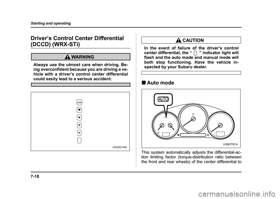
center differential, the “ ” indicator light will
flash and the auto mode and manual mode will
both stop functioning. Have the vehicle in-
spected by your Subaru dealer.
! Auto mode
This system automatically adjusts the differential-ac-
tion limiting factor (torque-distribution ratio between
the front and rear wheels) of the center differential to
UG3031AAUGB079CA
Page 288 of 491
7-19
Starting and operating
– CONTINUED –
suit driving and road-surface conditions. When the ig-
nition switch is turned ON, the “AUTO” indicator light
in the combination meter comes on. The system can
be switched to a manual mode. !Manual mode
The manual mode allows the driver to set the differen-
tial-action limiting factor of the center differential as
desired to suit driving and road-surface conditions.
When this mode is selected, the “AUTO” indicator light
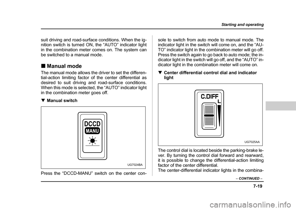
in the combination meter goes off. ! Manual switch
Press the “DCCD-MANU” switch on the center con- sole to switch from auto mode to manual mode. The
indicator light in the switch will come on, and the “AU-
TO” indicator light in the combination meter will go off.
Press the switch again to go back to auto mode; the in-
dicator light in the switch will go off, and the “AUTO” in-
dicator light in the combination meter will come on. !
Center differential control dial and indicator
light
The control dial is located beside the parking-brake le-
ver. By turning the control dial forward and rearward,
it is possible to change the differential-action limiting
factor of the center differential.
The center-differential indicator lights in the combina-
MANU
UG7024BA
UG7025AA