2004 SUBARU FORESTER replace
[x] Cancel search: replacePage 1 of 2870

FUJI HEAVY INDUSTRIES LTD. G8080GE7
2004 FORESTER SERVICE MANUAL QUICK REFERENCE INDEX
BODY SECTION
This service manual has been prepared
to provide SUBARU service personnel
with the necessary information and data
for the correct maintenance and repair
of SUBARU vehicles.
This manual includes the procedures
for maintenance, disassembling, reas-
sembling, inspection and adjustment of
components and diagnostics for guid-
ance of experienced mechanics.
Please peruse and utilize this manual
fully to ensure complete repair work for
satisfying our customers by keeping
their vehicle in optimum condition.
When replacement of parts during
repair work is needed, be sure to use
SUBARU genuine parts.
All information, illustration and specifi-
cations contained in this manual are
based on the latest product information
available at the time of publication
approval.HVAC SYSTEM
(HEATER, VENTILATOR AND A/C)AC
HVAC SYSTEM (AUTO A/C)
(DIAGNOSTIC)AC
AIRBAG SYSTEM AB
AIRBAG SYSTEM (DIAGNOSTIC) AB
SEAT BELT SYSTEM SB
LIGHTING SYSTEM LI
WIPER AND WASHER SYSTEM WW
ENTERTAINMENT ET
COMMUNICATION SYSTEM COM
GLASS/WINDOW/MIRROR GW
BODY STRUCTURE BS
INSTRUMENTATION/DRIVER INFO IDI
SEAT SE
SECURITY AND LOCK SL
SUNROOF/T-TOP/CONVERTIBLE TOP
(SUNROOF)SR
EXTERIOR/INTERIOR TRIM EI
EXTERIOR BODY PANEL EB
Page 23 of 2870
AC-21
HVAC SYSTEM (HEATER, VENTILATOR AND A/C)
General Description
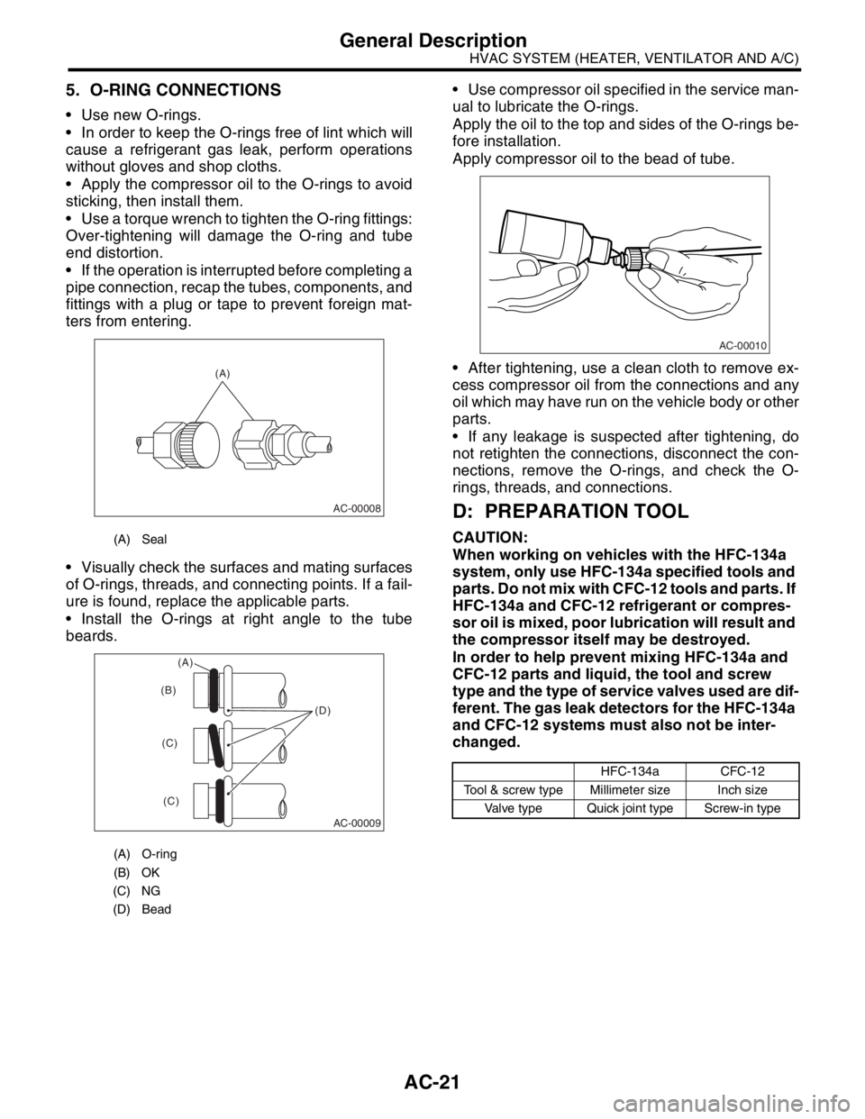
5. O-RING CONNECTIONS
Use new O-rings.
In order to keep the O-rings free of lint which will
cause a refrigerant gas leak, perform operations
without gloves and shop cloths.
Apply the compressor oil to the O-rings to avoid
sticking, then install them.
Use a torque wrench to tighten the O-ring fittings:
Over-tightening will damage the O-ring and tube
end distortion.
If the operation is interrupted before completing a
pipe connection, recap the tubes, components, and
fittings with a plug or tape to prevent foreign mat-
ters from entering.
Visually check the surfaces and mating surfaces
of O-rings, threads, and connecting points. If a fail-
ure is found, replace the applicable parts.
Install the O-rings at right angle to the tube
beards. Use compressor oil specified in the service man-
ual to lubricate the O-rings.
Apply the oil to the top and sides of the O-rings be-
fore installation.
Apply compressor oil to the bead of tube.
After tightening, use a clean cloth to remove ex-
cess compressor oil from the connections and any
oil which may have run on the vehicle body or other
parts.
If any leakage is suspected after tightening, do
not retighten the connections, disconnect the con-
nections, remove the O-rings, and check the O-
rings, threads, and connections.
D: PREPARATION TOOL
CAUTION:
When working on vehicles with the HFC-134a
system, only use HFC-134a specified tools and
parts. Do not mix with CFC-12 tools and parts. If
HFC-134a and CFC-12 refrigerant or compres-
sor oil is mixed, poor lubrication will result and
the compressor itself may be destroyed.
In order to help prevent mixing HFC-134a and
CFC-12 parts and liquid, the tool and screw
type and the type of service valves used are dif-
ferent. The gas leak detectors for the HFC-134a
and CFC-12 systems must also not be inter-
changed.(A) Seal
(A) O-ring
(B) OK
(C) NG
(D) Bead
(A)
AC-00008
AC-00009
(D) (B)
(C)
(C)
(A)
HFC-134a CFC-12
Tool & screw type Millimeter size Inch size
Valve type Quick joint type Screw-in type
AC-00010
Page 27 of 2870

AC-25
HVAC SYSTEM (HEATER, VENTILATOR AND A/C)
Refrigerant Pressure with Manifold Gauge Set
2. Refrigerant Pressure with Manifold Gauge Set
A: OPERATION
1) Place the vehicle in the shade and draftless condition.
2) Connect the manifold gauge set.
3) Open the front windows and close all doors.
4) Open the hood.
5) Increase the engine speed to 1,500 rpm.
6) Turn ON the A/C switch.
7) Turn the temperature control dial to MAX COOL.
8) Set the air inlet select switch to RECIRC position.
9) Turn the fan dial to HI.
10) Read the gauge.
Standard:
Low pressure: 127 — 196 kPa (1.3 — 2.0 kg/cm
2, 18 — 28 psi)
High pressure: 1,471 — 1, 667 kPa (15 — 17 kg/cm2, 213 — 242 psi)
Ambient temperature: 30 — 35
°C (86 — 95°F)
B: INSPECTION
Symptom Probable cause Repair order
High-pressure side is unusually high. Defective condenser fan motor
Clogged condenser fin
Too much refrigerant
Air inside the system
Defective receiver dryer Replace the fan motor.
Clean the condenser fin.
Discharge refrigerant.
Replace the receiver dryer.
After reevacuating the receiver dryer,
charge appropriate amount of refriger-
ant.
High-pressure side is unusually low. Defective compressor
Not enough refrigerant
Clogged expansion valve
Expansion valve frozen temporarily by
moisture Replace the compressor.
Check for leaks.
Replace the expansion valve.
Fully evacuate the expansion valve.
Low-pressure side is unusually high. Defective compressor
Defective expansion valve
Too much refrigerant Replace the compressor.
Replace the expansion valve.
Discharge refrigerant.
Low-pressure side is unusually low. Not enough refrigerant
Clogged expansion valve
Expansion valve frozen temporarily by
moisture
Saturated receiver dryer Check for leaks.
Replace the expansion valve.
Replace the receiver dryer.
Page 33 of 2870

AC-31
HVAC SYSTEM (HEATER, VENTILATOR AND A/C)
Compressor Oil
6. Compressor Oil
A: OPERATION
NOTE:
Before making repairs, conduct the oil return oper-
ation to return the compressor oil in circulation with
the refrigerant to the compressor.
1) Increase the engine speed to 1,500 rpm.
2) Turn ON the A/C switch.
3) Turn the temperature control dial to MAX COOL.
4) Set the air inlet select switch to RECIRC posi-
tion.
5) Turn the fan dial to HI.
6) Leave in this condition for 10 minutes.
B: REPLACEMENT
NOTE:
If a component is replaced, add an appropriate
amount of compressor oil (same as the amount of
remaining oil in removed component).
When replacing the compressor, the new com-
pressor will already have the specified amount of
oil in it. Install the new compressor after removing
the same amount of oil that is remaining in the com-
pressor removed.
Replacement parts Amount of oil replenishment
EvaporatorApprox. 50 cm
3
(1.7 US fl oz, 1.8 Imp fl oz)
CondenserApprox. 30 cm
3
(1.0 US fl oz, 1.1 Imp fl oz)
HoseApprox. 10 cm
3
(0.4 US fl oz, 0.4 Imp fl oz)
Receiver dryerApprox. 10 cm
3
(0.4 US fl oz, 0.4 Imp fl oz)
Page 35 of 2870
AC-33
HVAC SYSTEM (HEATER, VENTILATOR AND A/C)
Blower Resistor (Manual A/C Model)
8. Blower Resistor (Manual A/C
Model)
A: REMOVAL
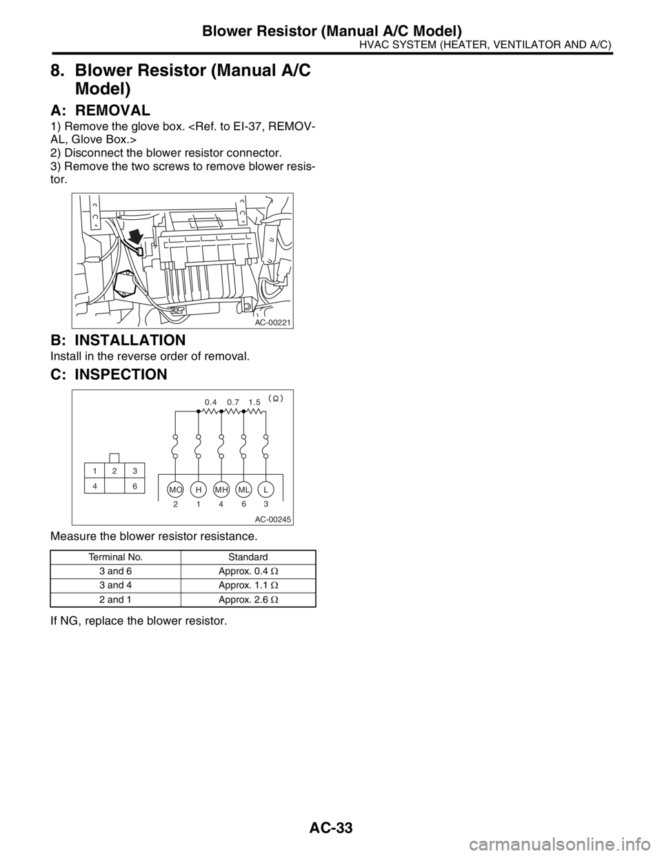
1) Remove the glove box.
2) Disconnect the blower resistor connector.
3) Remove the two screws to remove blower resis-
tor.
B: INSTALLATION
Install in the reverse order of removal.
C: INSPECTION
Measure the blower resistor resistance.
If NG, replace the blower resistor.
Terminal No. Standard
3 and 6 Approx. 0.4 Ω
3 and 4 Approx. 1.1 Ω
2 and 1 Approx. 2.6 Ω
AC-00221
AC-00245
MOHMHMLL
23 6
4 1
0.4 0.7 1.5
12 3
46
Page 38 of 2870
AC-36
HVAC SYSTEM (HEATER, VENTILATOR AND A/C)
Compressor
11.Compressor
A: INSPECTION
1. MAGNETIC CLUTCH CLEARANCE
1) Check the clearance of the entire circumference
around the drive plate and pulley.
Standard:
0.3 — 0.6 mm (0.0118 — 0.0236 in)
2. MAGNETIC CLUTCH OPERATION
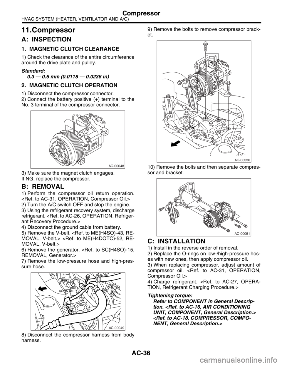
1) Disconnect the compressor connector.
2) Connect the battery positive (+) terminal to the
No. 3 terminal of the compressor connector.
3) Make sure the magnet clutch engages.
If NG, replace the compressor.
B: REMOVAL
1) Perform the compressor oil return operation.
2) Turn the A/C switch OFF and stop the engine.
3) Using the refrigerant recovery system, discharge
refrigerant.
4) Disconnect the ground cable from battery.
5) Remove the V-belt.
6) Remove the generator.
7) Remove the low-pressure hose and high-pres-
sure hose.
8) Disconnect the compressor harness from body
harness.9) Remove the bolts to remove compressor brack-
et.
10) Remove the bolts and then separate compres-
sor and bracket.
C: INSTALLATION
1) Install in the reverse order of removal.
2) Replace the O-rings on low-/high-pressure hos-
es with new ones, then apply compressor oil.
3) When replacing compressor, adjust amount of
compressor oil.
4) Charge refrigerant.
Tightening torque:
Refer to COMPONENT in General Descrip-
tion.
AC-00048
AC-00049
AC-00336
AC-00051
Page 39 of 2870
AC-37
HVAC SYSTEM (HEATER, VENTILATOR AND A/C)
Condenser
12.Condenser
A: REMOVAL
1) Using the refrigerant recovery system, discharge
refrigerant.
2) Disconnect the ground cable from battery.
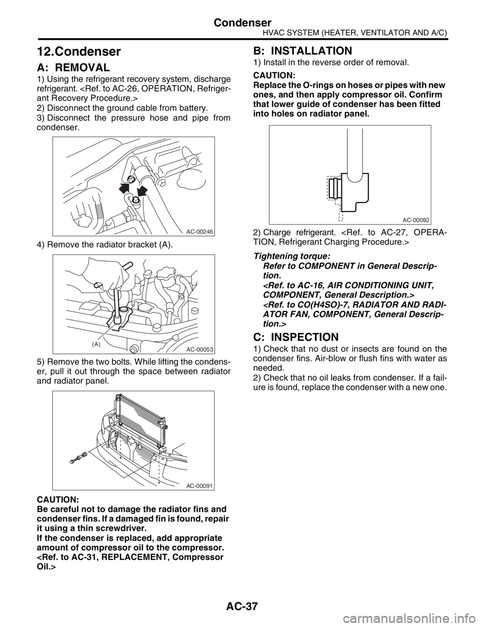
3) Disconnect the pressure hose and pipe from
condenser.
4) Remove the radiator bracket (A).
5) Remove the two bolts. While lifting the condens-
er, pull it out through the space between radiator
and radiator panel.
CAUTION:
Be careful not to damage the radiator fins and
condenser fins. If a damaged fin is found, repair
it using a thin screwdriver.
If the condenser is replaced, add appropriate
amount of compressor oil to the compressor.
B: INSTALLATION
1) Install in the reverse order of removal.
CAUTION:
Replace the O-rings on hoses or pipes with new
ones, and then apply compressor oil. Confirm
that lower guide of condenser has been fitted
into holes on radiator panel.
2) Charge refrigerant.
Tightening torque:
Refer to COMPONENT in General Descrip-
tion.
tion.>
C: INSPECTION
1) Check that no dust or insects are found on the
condenser fins. Air-blow or flush fins with water as
needed.
2) Check that no oil leaks from condenser. If a fail-
ure is found, replace the condenser with a new one.
AC-00246
AC-00053(A)
AC-00091
AC-00092
Page 42 of 2870
AC-40
HVAC SYSTEM (HEATER, VENTILATOR AND A/C)
Evaporator
15.Evaporator
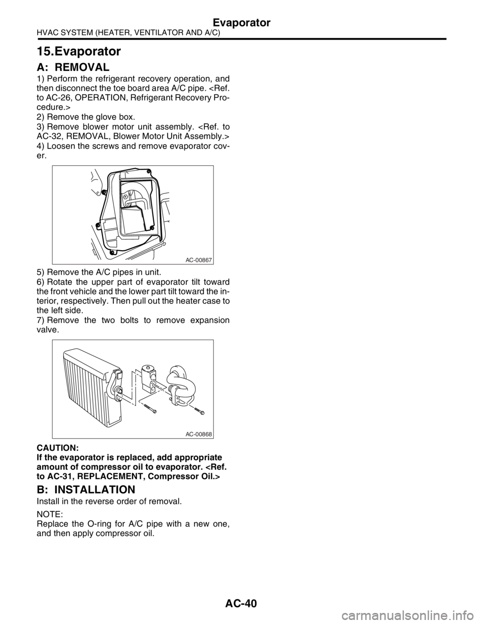
A: REMOVAL
1) Perform the refrigerant recovery operation, and
then disconnect the toe board area A/C pipe.
cedure.>
2) Remove the glove box.
3) Remove blower motor unit assembly.
4) Loosen the screws and remove evaporator cov-
er.
5) Remove the A/C pipes in unit.
6) Rotate the upper part of evaporator tilt toward
the front vehicle and the lower part tilt toward the in-
terior, respectively. Then pull out the heater case to
the left side.
7) Remove the two bolts to remove expansion
valve.
CAUTION:
If the evaporator is replaced, add appropriate
amount of compressor oil to evaporator.
B: INSTALLATION
Install in the reverse order of removal.
NOTE:
Replace the O-ring for A/C pipe with a new one,
and then apply compressor oil.
AC-00867
AC-00868