Page 1003 of 2870

CO(H4SO)-20
COOLING
Engine Coolant
B: INSPECTION
1. RELATIONSHIP OF SUBARU COOLANT
CONCENTRATION AND FREEZING TEM-
PERATURE
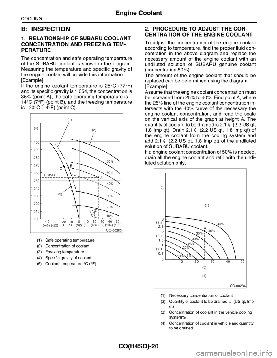
The concentration and safe operating temperature
of the SUBARU coolant is shown in the diagram.
Measuring the temperature and specific gravity of
the engine coolant will provide this information.
[Example]
If the engine coolant temperature is 25°C (77°F)
and its specific gravity is 1.054, the concentration is
35% (point A), the safe operating temperature is −
14°C (7°F) (point B), and the freezing temperature
is −20°C (−4°F) (point C).
2. PROCEDURE TO ADJUST THE CON-
CENTRATION OF THE ENGINE COOLANT
To adjust the concentration of the engine coolant
according to temperature, find the proper fluid con-
centration in the above diagram and replace the
necessary amount of the engine coolant with an
undiluted solution of SUBARU genuine coolant
(concentration 50%).
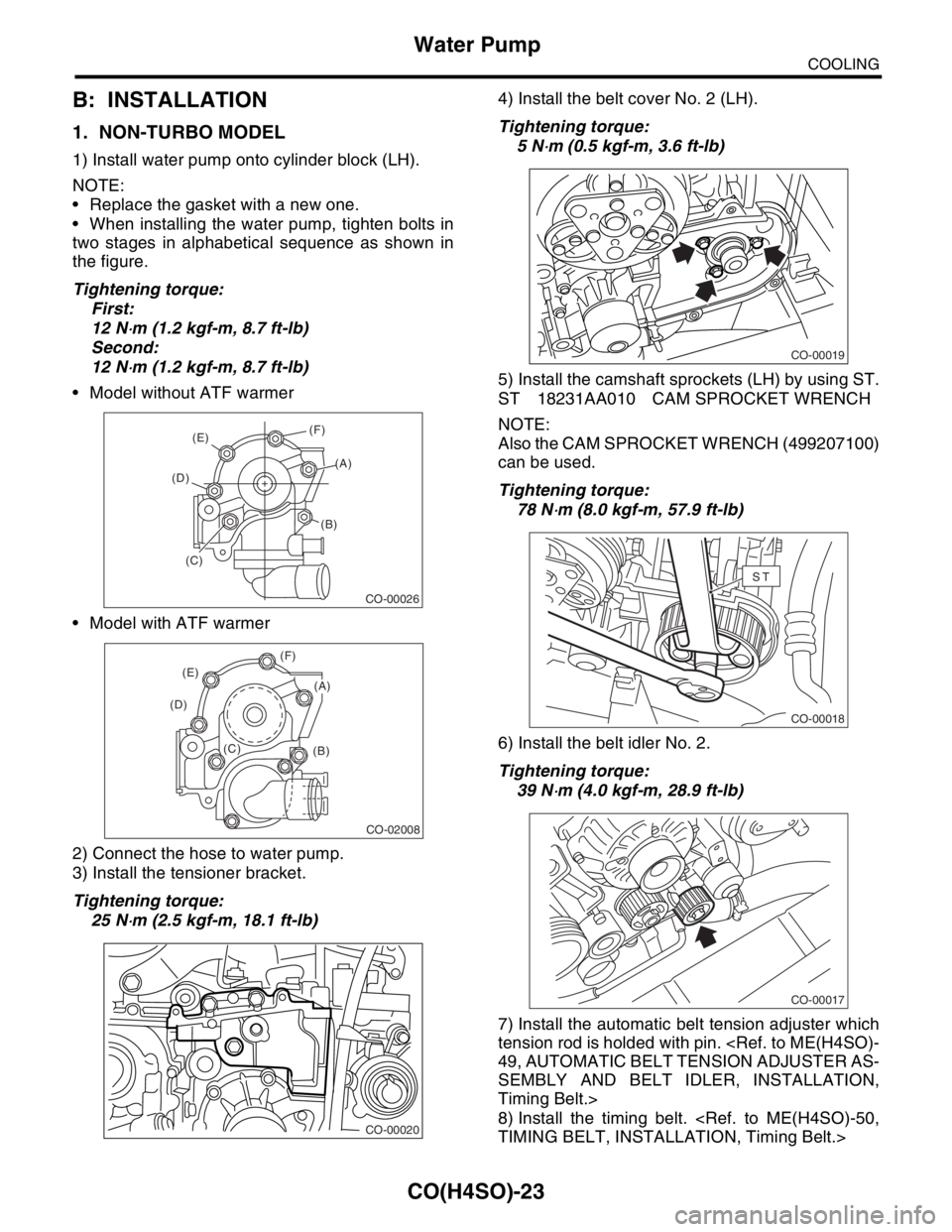
The amount of the engine coolant that should be
replaced can be determined using the diagram.
[Example]
Assume that the engine coolant concentration must
be increased from 25% to 40%. Find point A, where
the 25% line of the engine coolant concentration in-
tersects with the 40% curve of the necessary the
engine coolant concentration, and read the scale
on the vertical axis of the graph at height A. The
quantity of coolant to be drained is 2.12 (2.2 US qt,
1.8 Imp qt). Drain 2.12 (2.2 US qt, 1.8 Imp qt) of
the engine coolant from the cooling system and
add 2.12 (2.2 US qt, 1.8 Imp qt) of the undiluted
solution of SUBARU coolant.
If a engine coolant concentration of 50% is needed,
drain all the engine coolant and refill with the undi-
luted solution only.
(1) Safe operating temperature
(2) Concentration of coolant
(3) Freezing temperature
(4) Specific gravity of coolant
(5) Coolant temperature °C (°F)
CO-00283
60%
(1.054)
1.000 1.010 1.020
1.030
1.040
1.050
1.060
1.070 1.080 1.090
1.100(1)
(2)
(3)
(5) (4)B
A C
-40
(-40) (-22)(-4)
(14)(32)(50) (68) (86) (104) (122) -30-20 -1001020304050
(77 F)
50%
40%
30%
20%
25 C10%
(1) Necessary concentration of coolant
(2) Quantity of coolant to be drained 2 (US qt, Imp
qt)
(3) Concentration of coolant in the vehicle cooling
system%
(4) Concentration of coolant in vehicle and quantity
to be drained
CO-00284
10 0 12 3
(1.1,
0.9)(2.1,
1.8) (3.2,
2.6)
10%15%25%
20%30%35%40%45%
A
20 30 40 50
(1) (2)
(3)
(4)
Page 1004 of 2870
CO(H4SO)-21
COOLING
Water Pump
4. Water Pump
A: REMOVAL
1. NON-TURBO MODEL
1) Remove the radiator.
REMOVAL, Radiator.>
2) Remove the V-belts.
3) Remove the timing belt.
AL, Timing Belt.>
4) Remove the automatic belt tension adjuster.
5) Remove the belt idler No. 2.
6) Remove the camshaft sprocket (LH) by using
ST.
ST 18231AA010 CAM SPROCKET WRENCH
NOTE:
Also the CAM SPROCKET WRENCH (499207100)
can be used.7) Remove the belt cover No. 2 (LH).
8) Remove the tensioner bracket.
9) Disconnect the hose from water pump.
10) Remove the water pump.
CO-00016
CO-00017
CO-00018
ST
CO-00019
CO-00020
CO-00021
Page 1005 of 2870
CO(H4SO)-22
COOLING
Water Pump
2. TURBO MODEL
1) Remove the radiator.
REMOVAL, Radiator.>
2) Remove the V-belts.
REMOVAL, V-belt.>
3) Remove the timing belt.
58, REMOVAL, Timing Belt Assembly.>
4) Remove the automatic belt tension adjuster (A).
5) Remove the belt idler (B).
6) Remove the belt idler No. 2 (C).
7) Remove the camshaft position sensor. (2.0 L mod-
el)
shaft Position Sensor.>
8) Remove the cam sprockets (LH) by using ST.
ST 499977500 CAM SPROCKET WRENCH
(Intake)
ST 499207400 CAM SPROCKET WRENCH
(Exhaust)9) Remove the belt cover No. 2 (LH).
10) Remove the tensioner bracket.
11) Disconnect the hose from water pump.
12) Remove the water pump.
CO-00023
(A)
(B)
(C)
ME-00710
ME-00709
CO-00024
CO-00025
CO-00021
Page 1006 of 2870

CO(H4SO)-23
COOLING
Water Pump
B: INSTALLATION
1. NON-TURBO MODEL
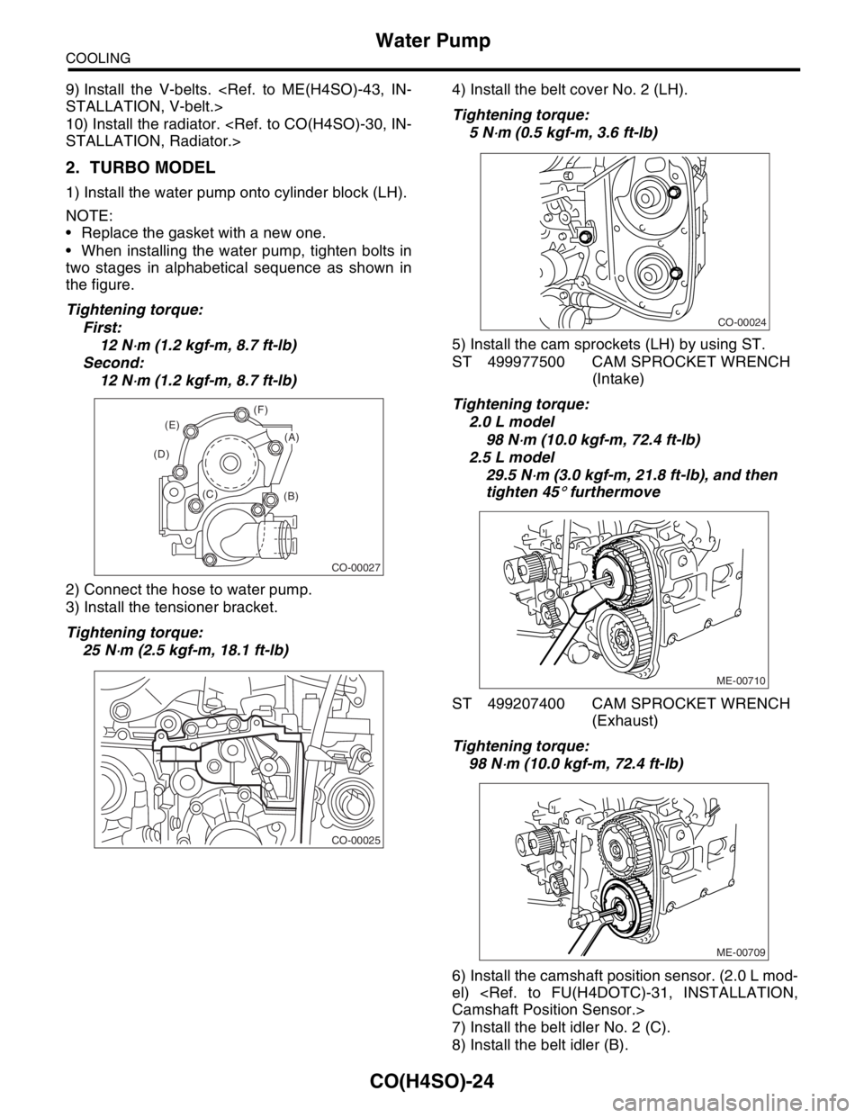
1) Install water pump onto cylinder block (LH).
NOTE:
Replace the gasket with a new one.
When installing the water pump, tighten bolts in
two stages in alphabetical sequence as shown in
the figure.
Tightening torque:
First:
12 N
⋅m (1.2 kgf-m, 8.7 ft-lb)
Second:
12 N
⋅m (1.2 kgf-m, 8.7 ft-lb)
Model without ATF warmer
Model with ATF warmer
2) Connect the hose to water pump.
3) Install the tensioner bracket.
Tightening torque:
25 N
⋅m (2.5 kgf-m, 18.1 ft-lb)4) Install the belt cover No. 2 (LH).
Tightening torque:
5 N
⋅m (0.5 kgf-m, 3.6 ft-lb)
5) Install the camshaft sprockets (LH) by using ST.
ST 18231AA010 CAM SPROCKET WRENCH
NOTE:
Also the CAM SPROCKET WRENCH (499207100)
can be used.
Tightening torque:
78 N
⋅m (8.0 kgf-m, 57.9 ft-lb)
6) Install the belt idler No. 2.
Tightening torque:
39 N
⋅m (4.0 kgf-m, 28.9 ft-lb)
7) Install the automatic belt tension adjuster which
tension rod is holded with pin.
49, AUTOMATIC BELT TENSION ADJUSTER AS-
SEMBLY AND BELT IDLER, INSTALLATION,
Timing Belt.>
8) Install the timing belt.
TIMING BELT, INSTALLATION, Timing Belt.>
CO-00026
(E)
(D)
(B)
(C)(A) (F)
CO-02008
(B) (C) (D)(E)(F)
(A)
CO-00020
CO-00019
CO-00018
ST
CO-00017
Page 1007 of 2870

CO(H4SO)-24
COOLING
Water Pump
9) Install the V-belts.
STALLATION, V-belt.>
10) Install the radiator.
STALLATION, Radiator.>
2. TURBO MODEL
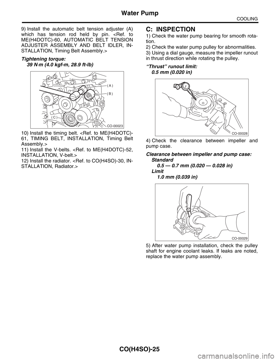
1) Install the water pump onto cylinder block (LH).
NOTE:
Replace the gasket with a new one.
When installing the water pump, tighten bolts in
two stages in alphabetical sequence as shown in
the figure.
Tightening torque:
First:
12 N
⋅m (1.2 kgf-m, 8.7 ft-lb)
Second:
12 N
⋅m (1.2 kgf-m, 8.7 ft-lb)
2) Connect the hose to water pump.
3) Install the tensioner bracket.
Tightening torque:
25 N
⋅m (2.5 kgf-m, 18.1 ft-lb)4) Install the belt cover No. 2 (LH).
Tightening torque:
5 N
⋅m (0.5 kgf-m, 3.6 ft-lb)
5) Install the cam sprockets (LH) by using ST.
ST 499977500 CAM SPROCKET WRENCH
(Intake)
Tightening torque:
2.0 L model
98 N
⋅m (10.0 kgf-m, 72.4 ft-lb)
2.5 L model
29.5 N
⋅m (3.0 kgf-m, 21.8 ft-lb), and then
tighten 45
° furthermove
ST 499207400 CAM SPROCKET WRENCH
(Exhaust)
Tightening torque:
98 N
⋅m (10.0 kgf-m, 72.4 ft-lb)
6) Install the camshaft position sensor. (2.0 L mod-
el)
Camshaft Position Sensor.>
7) Install the belt idler No. 2 (C).
8) Install the belt idler (B).
CO-00027
(B) (C) (D)(E)(F)
(A)
CO-00025
CO-00024
ME-00710
ME-00709
Page 1008 of 2870

CO(H4SO)-25
COOLING
Water Pump
9) Install the automatic belt tension adjuster (A)
which has tension rod held by pin.
ME(H4DOTC)-60, AUTOMATIC BELT TENSION
ADJUSTER ASSEMBLY AND BELT IDLER, IN-
STALLATION, Timing Belt Assembly.>
Tightening torque:
39 N
⋅m (4.0 kgf-m, 28.9 ft-lb)
10) Install the timing belt.
61, TIMING BELT, INSTALLATION, Timing Belt
Assembly.>
11) Install the V-belts.
INSTALLATION, V-belt.>
12) Install the radiator.
STALLATION, Radiator.>
C: INSPECTION
1) Check the water pump bearing for smooth rota-
tion.
2) Check the water pump pulley for abnormalities.
3) Using a dial gauge, measure the impeller runout
in thrust direction while rotating the pulley.
“Thrust” runout limit:
0.5 mm (0.020 in)
4) Check the clearance between impeller and
pump case.
Clearance between impeller and pump case:
Standard
0.5 — 0.7 mm (0.020 — 0.028 in)
Limit
1.0 mm (0.039 in)
5) After water pump installation, check the pulley
shaft for engine coolant leaks. If leaks are noted,
replace the water pump assembly.
CO-00023
(A)
(B)
(C)
CO-00028
CO-00029
Page 1009 of 2870
CO(H4SO)-26
COOLING
Thermostat
5. Thermostat
A: REMOVAL
1) Set the vehicle on a lift.
2) Lift-up the vehicle.
3) Remove the under cover.
4) Drain the engine coolant completely.
CO(H4SO)-19, DRAINING OF ENGINE COOL-
ANT, REPLACEMENT, Engine Coolant.>
5) Disconnect the radiator outlet hose from thermo-
stat cover.
NON-TURBO MODEL
6) Disconnect the radiator outlet hose.
TURBO MODEL7) Remove the thermostat cover and gasket, and
pull out the thermostat.
B: INSTALLATION
1) Install the thermostat in the water pump, and
then install the thermostat cover together with a
gasket.
NOTE:
When reinstalling the thermostat, use a new gas-
ket.
The thermostat must be installed with the jiggle
pin (A) facing to front side.
Tightening torque:
6.5 N
⋅m (0.66 kgf-m, 4.8 ft-lb)
2) Fill engine coolant.
FILLING OF ENGINE COOLANT, REPLACE-
MENT, Engine Coolant.>
CO-00009
CO-00076
CO-00030
CO-00031
CO-00032
(A)
Page 1010 of 2870
CO(H4SO)-27
COOLING
Thermostat
C: INSPECTION
Replace the thermostat if the valve does not close
completely at an ambient temperature or if the fol-
lowing test shows unsatisfactory results.
Immerse the thermostat and thermometer in water.
Raise water temperature gradually, and measure
the temperature and valve lift when the valve be-
gins to open and when the valve is fully opened.
During the test, agitate the water for even temper-
ature distribution. The measurement should be to
the specification.
Starts to open:
Non-turbo model
80 — 84
°C (176 — 183°F)
Turbo model
76 — 80
°C (169 — 176°F)
Fully opens:
Non-turbo model
95
°C (203°F)
Turbo model
91
°C (196°F)
(A) Thermometer
(B) Thermostat
CO-00033
(A)
(B)