Page 2750 of 2870
5MT-38
MANUAL TRANSMISSION AND DIFFERENTIAL
Manual Transmission Assembly
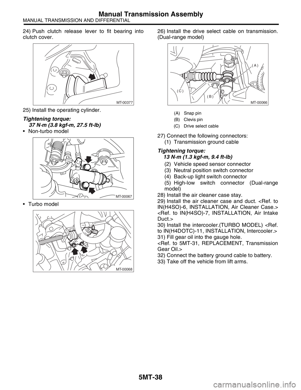
24) Push clutch release lever to fit bearing into
clutch cover.
25) Install the operating cylinder.
Tightening torque:
37 N·m (3.8 kgf-m, 27.5 ft-lb)
Non-turbo model
Turbo model26) Install the drive select cable on transmission.
(Dual-range model)
27) Connect the following connectors:
(1) Transmission ground cable
Tightening torque:
13 N·m (1.3 kgf-m, 9.4 ft-lb)
(2) Vehicle speed sensor connector
(3) Neutral position switch connector
(4) Back-up light switch connector
(5) High-low switch connector (Dual-range
model)
28) Install the air cleaner case stay.
29) Install the air cleaner case and duct.
IN(H4SO)-6, INSTALLATION, Air Cleaner Case.>
Duct.>
30) Install the intercooler.(TURBO MODEL)
to IN(H4DOTC)-11, INSTALLATION, Intercooler.>
31) Fill gear oil into the gauge hole.
Gear Oil.>
32) Connect the battery ground cable to battery.
33) Take off the vehicle from lift arms.
MT-00377
MT-00067
MT-00068
(A) Snap pin
(B) Clevis pin
(C) Drive select cable
MT-00066
(A)
(B)
(C)
Page 2751 of 2870
5MT-39
MANUAL TRANSMISSION AND DIFFERENTIAL
Transmission Mounting System
4. Transmission Mounting Sys-
tem
A: REMOVAL
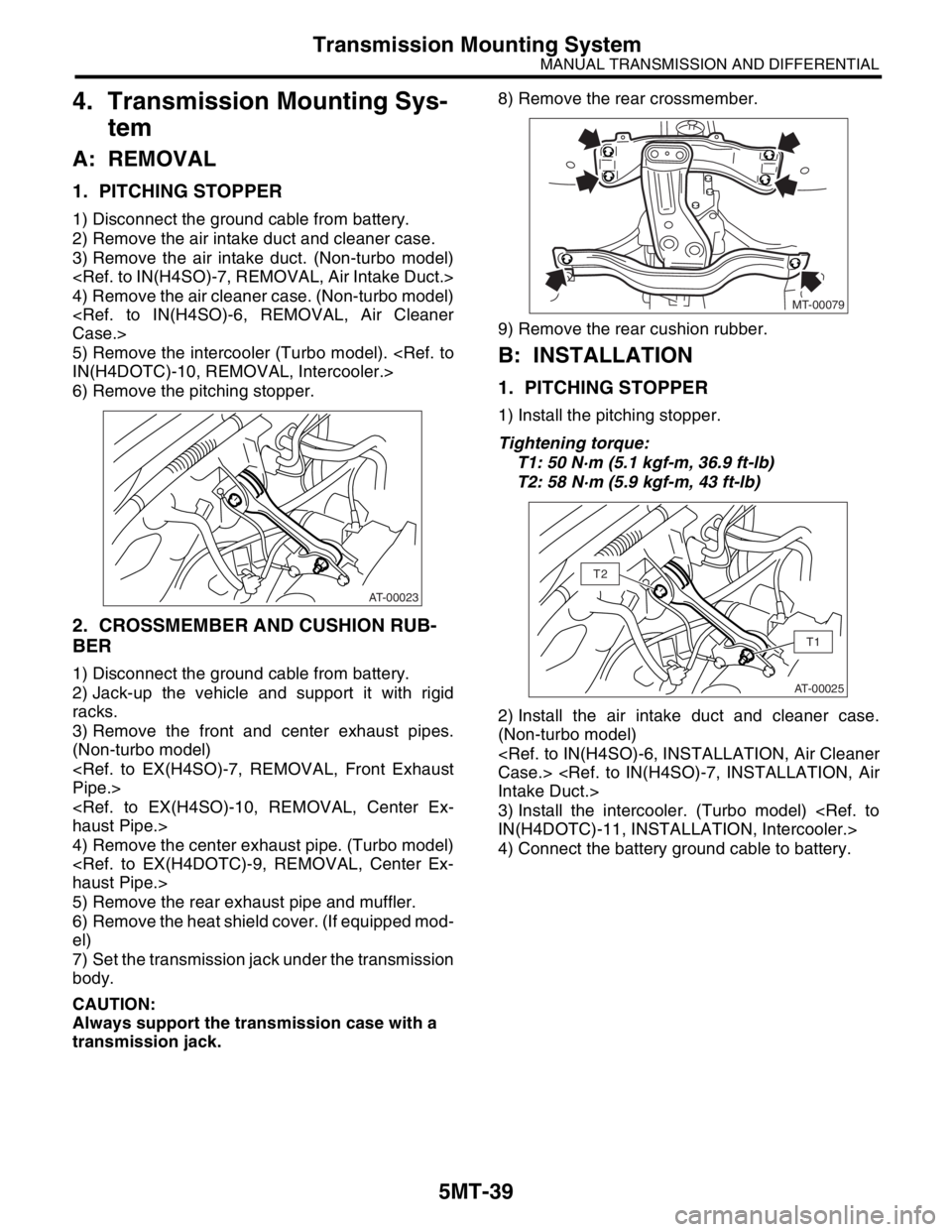
1. PITCHING STOPPER
1) Disconnect the ground cable from battery.
2) Remove the air intake duct and cleaner case.
3) Remove the air intake duct. (Non-turbo model)
4) Remove the air cleaner case. (Non-turbo model)
Case.>
5) Remove the intercooler (Turbo model).
IN(H4DOTC)-10, REMOVAL, Intercooler.>
6) Remove the pitching stopper.
2. CROSSMEMBER AND CUSHION RUB-
BER
1) Disconnect the ground cable from battery.
2) Jack-up the vehicle and support it with rigid
racks.
3) Remove the front and center exhaust pipes.
(Non-turbo model)
Pipe.>
haust Pipe.>
4) Remove the center exhaust pipe. (Turbo model)
haust Pipe.>
5) Remove the rear exhaust pipe and muffler.
6) Remove the heat shield cover. (If equipped mod-
el)
7) Set the transmission jack under the transmission
body.
CAUTION:
Always support the transmission case with a
transmission jack. 8) Remove the rear crossmember.
9) Remove the rear cushion rubber.
B: INSTALLATION
1. PITCHING STOPPER
1) Install the pitching stopper.
Tightening torque:
T1: 50 N·m (5.1 kgf-m, 36.9 ft-lb)
T2: 58 N·m (5.9 kgf-m, 43 ft-lb)
2) Install the air intake duct and cleaner case.
(Non-turbo model)
Case.>
Intake Duct.>
3) Install the intercooler. (Turbo model)
IN(H4DOTC)-11, INSTALLATION, Intercooler.>
4) Connect the battery ground cable to battery.
AT-00023
MT-00079
AT-00025
T1
T2
Page 2752 of 2870
5MT-40
MANUAL TRANSMISSION AND DIFFERENTIAL
Transmission Mounting System
2. CROSSMEMBER AND CUSHION RUB-
BER
1) Install the rear cushion rubber.
Tightening torque:
35 N·m (3.6 kgf-m, 26 ft-lb)
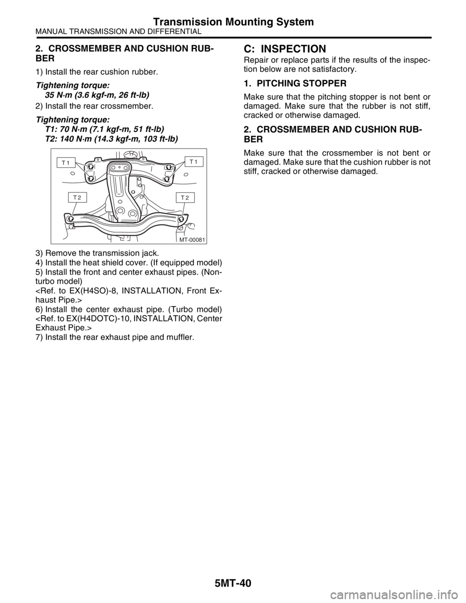
2) Install the rear crossmember.
Tightening torque:
T1: 70 N·m (7.1 kgf-m, 51 ft-lb)
T2: 140 N·m (14.3 kgf-m, 103 ft-lb)
3) Remove the transmission jack.
4) Install the heat shield cover. (If equipped model)
5) Install the front and center exhaust pipes. (Non-
turbo model)
haust Pipe.>
6) Install the center exhaust pipe. (Turbo model)
Exhaust Pipe.>
7) Install the rear exhaust pipe and muffler.
C: INSPECTION
Repair or replace parts if the results of the inspec-
tion below are not satisfactory.
1. PITCHING STOPPER
Make sure that the pitching stopper is not bent or
damaged. Make sure that the rubber is not stiff,
cracked or otherwise damaged.
2. CROSSMEMBER AND CUSHION RUB-
BER
Make sure that the crossmember is not bent or
damaged. Make sure that the cushion rubber is not
stiff, cracked or otherwise damaged.
MT-00081
T2T2
T1T1
Page 2753 of 2870
5MT-41
MANUAL TRANSMISSION AND DIFFERENTIAL
Oil Seal
5. Oil Seal
A: INSPECTION
Check the oil seal portion for leakage. If leakage is
found, replace the oil seal with a new one.
B: REPLACEMENT
1) Clean the transmission exterior.
2) Drain the gear oil completely.
3) Replace the gasket with a new one, and then
tighten the drain plug after draining gear oil.
Tightening torque:
44 N·m (4.5 kgf-m, 32.5 ft-lb) (Aluminum gas-
ket)
70 N·m (7.1 kgf-m, 51.6 ft-lb) (Copper gasket)
4) Remove the rear exhaust pipe and muffler.
5) Remove the heat shield cover. (If equipped mod-
el)
6) Remove the propeller shaft.
MOVAL, Propeller Shaft.>
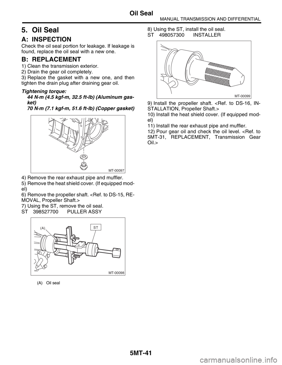
7) Using the ST, remove the oil seal.
ST 398527700 PULLER ASSY8) Using the ST, install the oil seal.
ST 498057300 INSTALLER
9) Install the propeller shaft.
STALLATION, Propeller Shaft.>
10) Install the heat shield cover. (If equipped mod-
el)
11) Install the rear exhaust pipe and muffler.
12) Pour gear oil and check the oil level.
5MT-31, REPLACEMENT, Transmission Gear
Oil.>
(A) Oil seal
MT-00097
MT-00098
(A)ST
MT-00099
Page 2754 of 2870
5MT-42
MANUAL TRANSMISSION AND DIFFERENTIAL
Differential Side Retainer Oil Seal
6. Differential Side Retainer Oil
Seal
A: INSPECTION
Check the differential side retainer oil seal for leak-
age of gear oil. If oil leaks, replace the oil seal.
B: REPLACEMENT
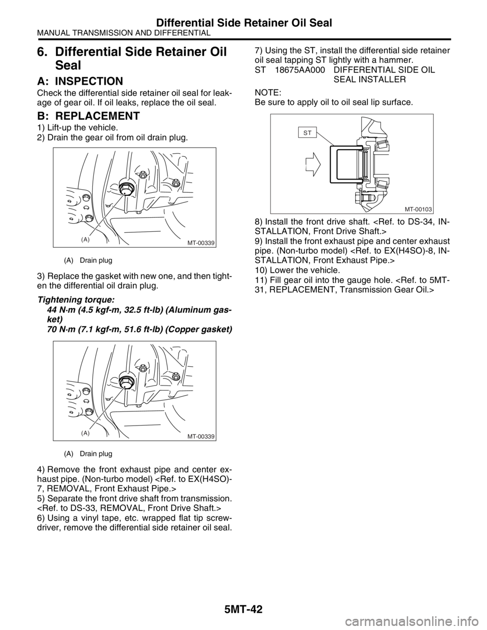
1) Lift-up the vehicle.
2) Drain the gear oil from oil drain plug.
3) Replace the gasket with new one, and then tight-
en the differential oil drain plug.
Tightening torque:
44 N·m (4.5 kgf-m, 32.5 ft-lb) (Aluminum gas-
ket)
70 N·m (7.1 kgf-m, 51.6 ft-lb) (Copper gasket)
4) Remove the front exhaust pipe and center ex-
haust pipe. (Non-turbo model)
7, REMOVAL, Front Exhaust Pipe.>
5) Separate the front drive shaft from transmission.
6) Using a vinyl tape, etc. wrapped flat tip screw-
driver, remove the differential side retainer oil seal.7) Using the ST, install the differential side retainer
oil seal tapping ST lightly with a hammer.
ST 18675AA000 DIFFERENTIAL SIDE OIL
SEAL INSTALLER
NOTE:
Be sure to apply oil to oil seal lip surface.
8) Install the front drive shaft.
STALLATION, Front Drive Shaft.>
9) Install the front exhaust pipe and center exhaust
pipe. (Non-turbo model)
STALLATION, Front Exhaust Pipe.>
10) Lower the vehicle.
11) Fill gear oil into the gauge hole.
31, REPLACEMENT, Transmission Gear Oil.>
(A) Drain plug
(A) Drain plug
(A)
MT-00339
(A)
MT-00339
MT-00103
ST
Page 2755 of 2870
5MT-43
MANUAL TRANSMISSION AND DIFFERENTIAL
Switches and Harness
7. Switches and Harness
A: REMOVAL
1. BACK-UP LIGHT AND NEUTRAL POSI-
TION SWITCH
1) Disconnect the ground cable from battery.
2) Remove the air intake duct and cleaner case.
Case.>
3) Remove the intercooler (Turbo model).
IN(H4DOTC)-10, REMOVAL, Intercooler.>
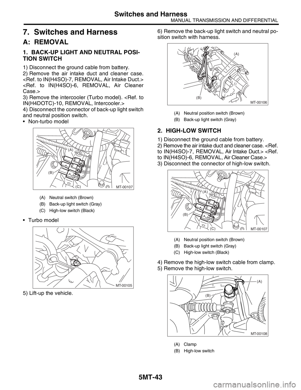
4) Disconnect the connector of back-up light switch
and neutral position switch.
Non-turbo model
Turbo model
5) Lift-up the vehicle.6) Remove the back-up light switch and neutral po-
sition switch with harness.
2. HIGH-LOW SWITCH
1) Disconnect the ground cable from battery.
2) Remove the air intake duct and cleaner case.
to IN(H4SO)-7, REMOVAL, Air Intake Duct.>
to IN(H4SO)-6, REMOVAL, Air Cleaner Case.>
3) Disconnect the connector of high-low switch.
4) Remove the high-low switch cable from clamp.
5) Remove the high-low switch.
(A) Neutral switch (Brown)
(B) Back-up light switch (Gray)
(C) High-low switch (Black)
MT-00107
(B)
(C)
(A)
MT-00105
(A) Neutral position switch (Brown)
(B) Back-up light switch (Gray)
(A) Neutral position switch (Brown)
(B) Back-up light switch (Gray)
(C) High-low switch (Black)
(A) Clamp
(B) High-low switch
MT-00106
(A)
(B)
MT-00107
(B)
(C)
(A)
MT-00108
(B)(A)
Page 2756 of 2870
5MT-44
MANUAL TRANSMISSION AND DIFFERENTIAL
Switches and Harness
B: INSTALLATION
1. BACK-UP LIGHT SWITCH AND NEU-
TRAL POSITION SWITCH
1) Install the back-up light switch and neutral posi-
tion switch with harness.
Tightening torque:
24.5 N·m (2.5 kgf-m, 18.1 ft-lb)
2) Connect the connector of back-up light switch
and neutral position switch.
3) Install the air intake duct and cleaner case.
to IN(H4SO)-7, INSTALLATION, Air Intake Duct.>
Case.>
4) Install the intercooler. (Turbo model)
cooler.>
5) Connect the battery ground cable to battery.
2. HIGH-LOW SWITCH
1) Install the high-low switch.
Tightening torque:
25 N·m (2.5 kgf-m, 18.1 ft-lb)
2) Install the high-low switch cable to clamp.
3) Connect the connector of high-low switch.
4) Install the air intake duct and cleaner case.
to IN(H4SO)-7, INSTALLATION, Air Intake Duct.>
Case.>
5) Connect the battery ground cable to battery.
(A) Neutral position switch (Brown)
(B) Back-up light switch (Gray)
MT-00106
(A)
(B)
Page 2757 of 2870
5MT-45
MANUAL TRANSMISSION AND DIFFERENTIAL
Switches and Harness
C: INSPECTION
1. BACK-UP LIGHT SWITCH
Inspect the back-up light switch.
SPECTION, Back-up Light System.>
2. NEUTRAL POSITION SWITCH
1) Turn the ignition switch to OFF.
2) Disconnect the connector of neutral position
switch.
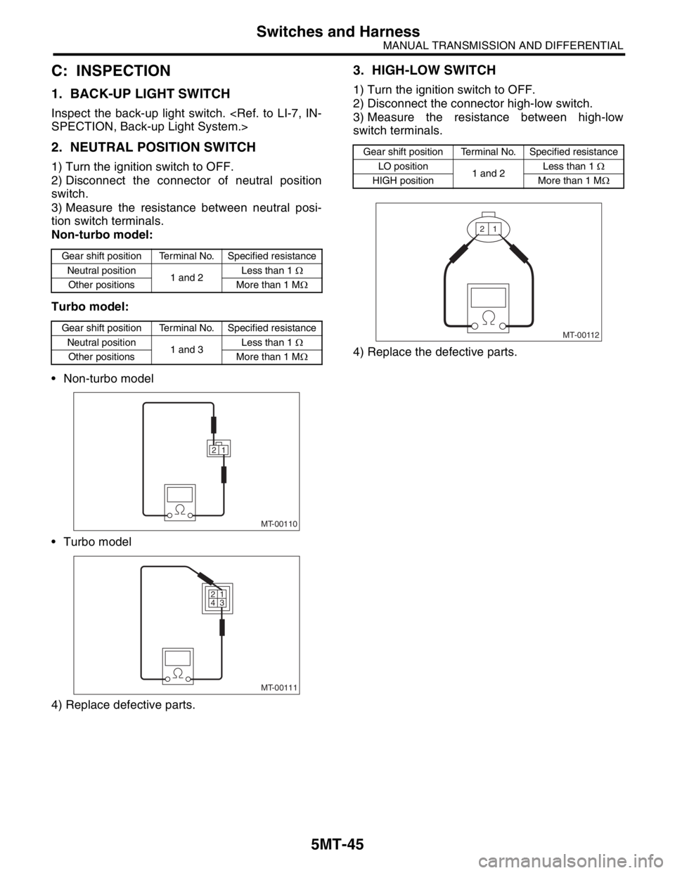
3) Measure the resistance between neutral posi-
tion switch terminals.
Non-turbo model:
Turbo model:
Non-turbo model
Turbo model
4) Replace defective parts.
3. HIGH-LOW SWITCH
1) Turn the ignition switch to OFF.
2) Disconnect the connector high-low switch.
3) Measure the resistance between high-low
switch terminals.
4) Replace the defective parts.
Gear shift position Terminal No. Specified resistance
Neutral position
1 and 2Less than 1 Ω
Other positions More than 1 MΩ
Gear shift position Terminal No. Specified resistance
Neutral position
1 and 3Less than 1 Ω
Other positions More than 1 MΩ
MT-00110
1 2
MT-00111
1 2
3 4
Gear shift position Terminal No. Specified resistance
LO position
1 and 2Less than 1 Ω
HIGH position More than 1 MΩ
MT-00112
1 2