2004 SUBARU FORESTER check engine
[x] Cancel search: check enginePage 2383 of 2870

4AT-70
AUTOMATIC TRANSMISSION
Air Bleeding of Control Valve
18.Air Bleeding of Control Valve
A: PROCEDURE
1) Lift-up the vehicle with shifting the select lever to
“P” range and applying the parking brake.
2) Connect the Subaru Select Monitor to the vehi-
cle.
3) Make sure there is no trouble code using Subaru
Select Monitor.
4) Using Subaru Select Monitor, check that the
ATF temperature is in less than 60°C (140°F).
5) Power OFF the Subaru Select Monitor.
6) Turn the ignition switch to “OFF”.
7) Shift the select lever to “R” range.
8) Depress the brake pedal fully until the air bleed-
ing is completed.
9) Turn the ignition switch to ON.
10) Shift the select lever to “P” range, and then wait
for more than 3 seconds.
11) Shift the select lever to “R” range, and then wait
for more than 3 seconds.
12) Shift the select lever to “N” range, and then wait
for more than 3 seconds.
13) Shift the select lever to “D” range, and then wait
for more than 3 seconds.
14) Shift the select lever to “N” range, and then wait
for more than 3 seconds.
15) Slightly depress the accelerator pedal fully.
16) Slightly release the accelerator pedal fully.
17) Start the engine.
18) Shift the select lever to “D” range.
19) Turn the Subaru Select Monitor switch to ON.
20) Select {Each System Check} in «Main Menu»
of Subaru Select Monitor.
21) On the «System Selection Menu» display
screen, select the “Transmission”. Air bleeding of
control valve starts on transmission. At this time,
the POWER indicator light in combination meter
blinks at 2 Hz. When the POWER indicator light
does not blink, repeat the procedures from step 4).
22) Air bleeding of control valve is finished when
blinking of POWER indicator light in combination
meter changes from 2 Hz to 0.5 Hz.
NOTE:
When blinking of POWER indicator light changes
from 2 Hz to 4 Hz during air bleeding, repeat the
procedure from step 4).
23) Shift the select lever to “N” range, and then turn
the ignition switch to OFF.
24) Shift the select lever to the “P” range, and then
finish the air bleeding.
Page 2399 of 2870

4AT-86
AUTOMATIC TRANSMISSION
ATF Cooler (With Warmer Function)
C: DISASSEMBLY
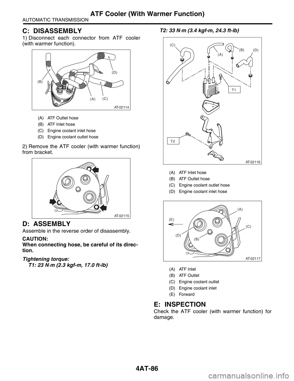
1) Disconnect each connector from ATF cooler
(with warmer function).
2) Remove the ATF cooler (with warmer function)
from bracket.
D: ASSEMBLY
Assemble in the reverse order of disassembly.
CAUTION:
When connecting hose, be careful of its direc-
tion.
Tightening torque:
T1: 23 N
⋅m (2.3 kgf-m, 17.0 ft-lb)T2: 33 N
⋅m (3.4 kgf-m, 24.3 ft-lb)
E: INSPECTION
Check the ATF cooler (with warmer function) for
damage.
(A) ATF Outlet hose
(B) ATF Inlet hose
(C) Engine coolant inlet hose
(D) Engine coolant outlet hose
AT-02114
(A) (B)(C)
(D)
AT-02115
(A) ATF Inlet hose
(B) ATF Outlet hose
(C) Engine coolant outlet hose
(D) Engine coolant inlet hose
(A) ATF Inlet
(B) ATF Outlet
(C) Engine coolant outlet
(D) Engine coolant inlet
(E) Forward
AT-02116
T1
T2
(B)
(D) (C)
(A)
AT-02117
(D)(B)(A)
(C)
(E)
Page 2465 of 2870

4AT(H4SO)-6
AUTOMATIC TRANSMISSION (DIAGNOSTIC)
General Description
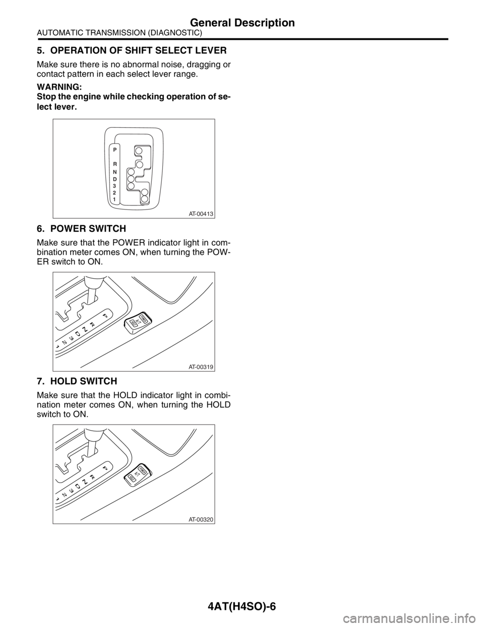
5. OPERATION OF SHIFT SELECT LEVER
Make sure there is no abnormal noise, dragging or
contact pattern in each select lever range.
WARNING:
Stop the engine while checking operation of se-
lect lever.
6. POWER SWITCH
Make sure that the POWER indicator light in com-
bination meter comes ON, when turning the POW-
ER switch to ON.
7. HOLD SWITCH
Make sure that the HOLD indicator light in combi-
nation meter comes ON, when turning the HOLD
switch to ON.
AT-00413
P
R
N
D
3
2
1
AT-00319
AT-00320
Page 2471 of 2870

4AT(H4SO)-12
AUTOMATIC TRANSMISSION (DIAGNOSTIC)
Transmission Control Module (TCM) I/O Signal
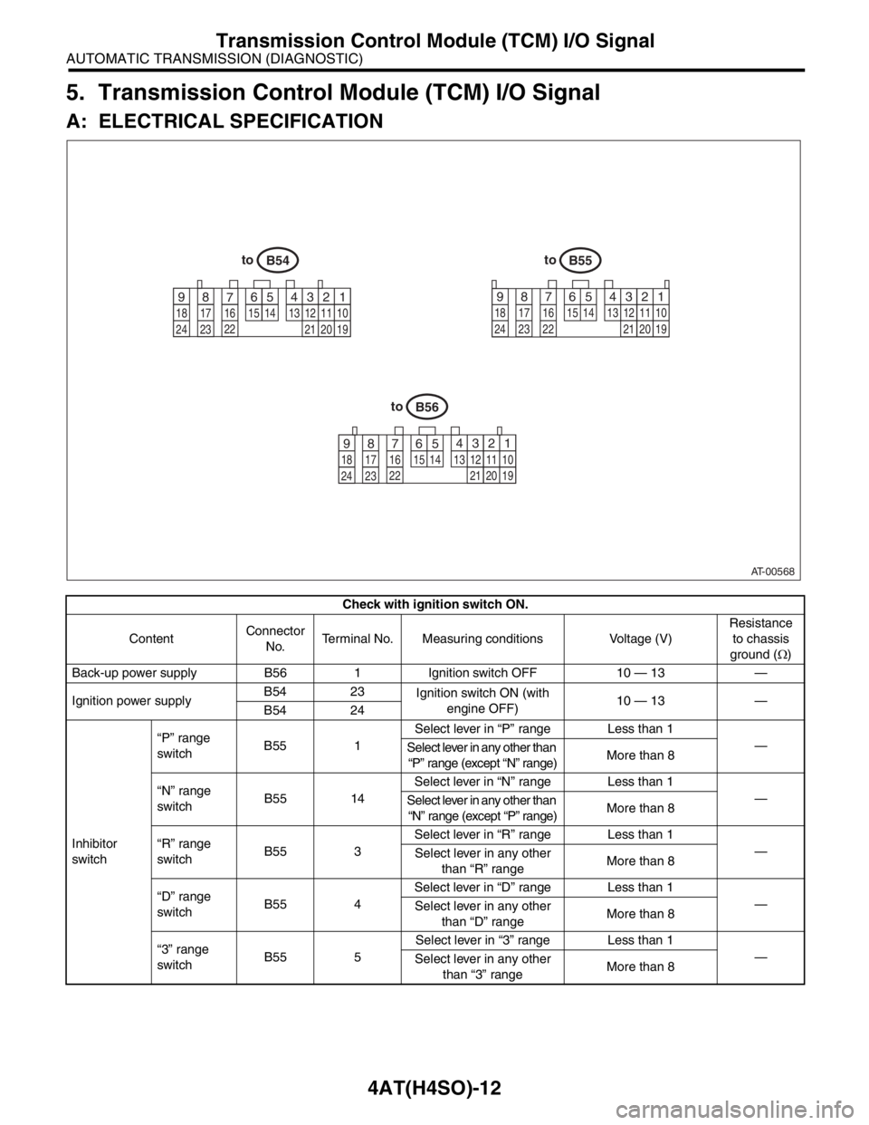
5. Transmission Control Module (TCM) I/O Signal
A: ELECTRICAL SPECIFICATION
Check with ignition switch ON.
ContentConnector
No.Terminal No. Measuring conditions Voltage (V)Resistance
to chassis
ground (Ω)
Back-up power supply B56 1 Ignition switch OFF 10 — 13 —
Ignition power supplyB54 23
Ignition switch ON (with
engine OFF)10 — 13 —
B54 24
Inhibitor
switch“P” range
switchB55 1Select lever in “P” range Less than 1
—
Select lever in any other than
“P” range (except “N” range)More than 8
“N” range
switchB55 14Select lever in “N” range Less than 1
—
Select lever in any other than
“N” range (except “P” range)More than 8
“R” range
switchB55 3Select lever in “R” range Less than 1
—
Select lever in any other
than “R” rangeMore than 8
“D” range
switchB55 4Select lever in “D” range Less than 1
—
Select lever in any other
than “D” rangeMore than 8
“3” range
switchB55 5Select lever in “3” range Less than 1
—
Select lever in any other
than “3” rangeMore than 8
AT-00568
toB54
1 2
7 8 9563 4
10 11 12
19 20 21 13 14 15 16 17 18
22
23
24
toB55
1 2 3 4
10 11 12
19 20 21 13
5 6
14 15
7 8 9
16 17 18
22 23 24
toB56
1 2
7 8 95 63 4
10 11 12
19 20 21 13 14 15
16 17 18
22
23
24
Page 2472 of 2870

4AT(H4SO)-13
AUTOMATIC TRANSMISSION (DIAGNOSTIC)
Transmission Control Module (TCM) I/O Signal
Inhibitor
switch“2” range
switchB55 6Select lever in “2” range Less than 1
—
Select lever in any other
than “2” rangeMore than 8
“1” range
switchB55 7Select lever in “1” range Less than 1
—
Select lever in any other
than “1” rangeMore than 8
Brake switch B55 12Brake pedal depressed More than 10.5
—
Brake pedal released Less than 1
Kick-down switch B55 11Throttle fully opened Less than 1
—
Throttle fully closed More than 6.5
AT OIL TEMP warning light B56 10Light ON Less than 1
—
Light OFF More than 9
Throttle position sensor B54 3Throttle fully closed 0.2 — 1.0
—
Throttle fully open 4.2 — 4.7
Throttle position sensor
power supplyB54 2Ignition switch ON (with
engine OFF)4.8 — 5.3 —
ATF temperature sensor B54 11ATF temperature 20°C
(68°F)1.6 — 2.0 2.1 k — 2.9 k
ATF temperature 80°C
(176°F)0.4 — 0.9 275 — 375
Rear vehicle speed sensor B55 24Vehicle stopped 0
450 — 650
Vehicle speed at least 20
km/h (12 MPH)More than 1 (AC range)
Front vehicle speed sensor B55 18Vehicle stopped 0
450 — 650
Vehicle speed at least 20
km/h (12 MPH)More than 1 (AC range)
Torque converter turbine
speed sensorB55 8Engine idling after warm-
up (D range)0
450 — 650
Engine idling after warm-
up (N range)More than 1 (AC range)
Vehicle speed output signal B56 17Vehicle speed at most 10
km/h (6 MPH)Less than 1 ←
→ More than 4—
Engine speed signal B55 17Ignition switch ON (with
engine OFF)More than 10.5
—
Ignition switch ON (with
engine ON)8 — 11
Cruise set signal B55 22When cruise control is set
(SET lamp ON)Less than 1
—
When cruise control is not
set (SET lamp OFF)More than 6.5
Torque control signal 1 B56 5Ignition switch ON (with
engine ON)More than 4 —
Torque control signal 2 B56 14Ignition switch ON (with
engine ON)More than 4 —
Torque control cut signal B55 10Ignition switch ON
(After engine is warmed-up)8—
Intake manifold pressure
signalB54 1 Engine idling after warm-up 0.4 — 1.6 —
Shift solenoid 1 B54 221st or 4th gear More than 9
10 — 16
2nd or 3rd gear Less than 1
Shift solenoid 2 B54 51st or 2nd gear More than 9
10 — 16
3rd or 4th gear Less than 1 Check with ignition switch ON.
ContentConnector
No.Terminal No. Measuring conditions Voltage (V)Resistance
to chassis
ground (Ω)
Page 2473 of 2870

4AT(H4SO)-14
AUTOMATIC TRANSMISSION (DIAGNOSTIC)
Transmission Control Module (TCM) I/O Signal
Line pressure duty solenoid B54 9Ignition switch ON (with
engine OFF)
Throttle fully closed after
war m-up1.5 — 4.0
2.0 — 4.5
Ignition switch ON (with
engine OFF)
Throttle fully open after
war m-upLess than 0.5
Lock-up duty solenoid B54 7When lock up occurs More than 8.5
10 — 17
When lock up is released Less than 0.5
Transfer duty solenoid B54 6Fuse on FWD switch Less than 0.5
10 — 17 Fuse removed from FWD
switch (with throttle fully
open and with select lever
in 1st gear)More than 8.5
2-4 brake duty solenoid B54 18Throttle fully closed (with
engine OFF) after warm-up1.5 — 5.0
2.0 — 4.5
Throttle fully open (with
engine OFF) after warm-upLess than 0.5
2-4 brake timing solenoid B54 161st gear Less than 1
10 — 16
3rd gear More than 9
Low clutch timing solenoid B54 152nd gear Less than 1
10 — 16
4th gear More than 9
HOLD switch B55 16HOLD switch ON Less than 1 —
HOLD switch OFF More than 8 —
POWER switch B55 23POWER switch ON Less than 1 —
POWER switch OFF More than 10 —
POWER indicator light B56 11Light ON Less than 1 —
Light OFF More than 9 —
FWD switch B55 20Fuse removed 6 — 9.1 —
Fuse installed Less than 1 —
FWD indicator light B56 2Fused on FWD switch Less than 1 —
Fuse removed from FWD
switchMore than 9 —
ABS signal B55 21ABS switch ON Less than 1 —
ABS switch OFF 6.5 — 15 —
Sensor ground line 1 B54 20 — 0 Less than 1
Sensor ground line 2 B55 9 — 0 Less than 1
System ground lineB56 19
— 0 Less than 1
B54 21
Sensor ground line 3 B54 10 — 0 Less than 1
Sensor ground line 4 B54 19 — 0 Less than 1
AT diagnosis signal B56 21 Ignition switch ONLess than 1 ←
→ More than 4—
Data link signal (Subaru
Select Monitor)B56 15 — — —Check with ignition switch ON.
ContentConnector
No.Terminal No. Measuring conditions Voltage (V)Resistance
to chassis
ground (Ω)
Page 2476 of 2870

4AT(H4SO)-17
AUTOMATIC TRANSMISSION (DIAGNOSTIC)
Subaru Select Monitor
6. Subaru Select Monitor
A: OPERATION
1. READ DIAGNOSTIC TROUBLE CODE
(DTC)
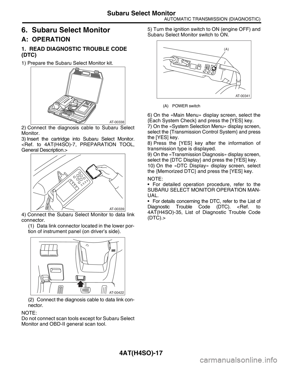
1) Prepare the Subaru Select Monitor kit.
2) Connect the diagnosis cable to Subaru Select
Monitor.
3) Insert the cartridge into Subaru Select Monitor.
4) Connect the Subaru Select Monitor to data link
connector.
(1) Data link connector located in the lower por-
tion of instrument panel (on driver’s side).
(2) Connect the diagnosis cable to data link con-
nector.
NOTE:
Do not connect scan tools except for Subaru Select
Monitor and OBD-II general scan tool.5) Turn the ignition switch to ON (engine OFF) and
Subaru Select Monitor switch to ON.
6) On the «Main Menu» display screen, select the
{Each System Check} and press the [YES] key.
7) On the «System Selection Menu» display screen,
select the {Transmission Control System} and press
the [YES] key.
8) Press the [YES] key after the information of
transmission type is displayed.
9) On the «Transmission Diagnosis» display screen,
select the {DTC Display} and press the [YES] key.
10) On the «DTC Display» display screen, select
the {Memorized DTC} and press the [YES] key.
NOTE:
For detailed operation procedure, refer to the
SUBARU SELECT MONITOR OPERATION MAN-
UAL.
For details concerning the DTC, refer to the List of
Diagnostic Trouble Code (DTC).
(DTC).>
AT-00338
AT-00339
AT-00422
(A) POWER switch
(A)
AT-00341
Page 2477 of 2870
![SUBARU FORESTER 2004 Service Repair Manual 4AT(H4SO)-18
AUTOMATIC TRANSMISSION (DIAGNOSTIC)
Subaru Select Monitor
2. READ CURRENT DATA
1) On the «Main Menu» display screen, select the {Each System Check} and press the [YES] key.
2) On the « SUBARU FORESTER 2004 Service Repair Manual 4AT(H4SO)-18
AUTOMATIC TRANSMISSION (DIAGNOSTIC)
Subaru Select Monitor
2. READ CURRENT DATA
1) On the «Main Menu» display screen, select the {Each System Check} and press the [YES] key.
2) On the «](/manual-img/17/57426/w960_57426-2476.png)
4AT(H4SO)-18
AUTOMATIC TRANSMISSION (DIAGNOSTIC)
Subaru Select Monitor
2. READ CURRENT DATA
1) On the «Main Menu» display screen, select the {Each System Check} and press the [YES] key.
2) On the «System Selection Menu» display screen, select the {Transmission Control System} and press the
[YES] key.
3) Press the [YES] key after the information of transmission type is displayed.
4) On the «Transmission Diagnosis» display screen, select the {Current Data Display & Save} and press the
[YES] key.
5) On the «Data Display Menu» display screen, select the {Data Display} and press the [YES] key.
6) Using the scroll key, move the display screen up or down until desired data is shown.
A list of the support data is shown in the following table.
NOTE:
For detailed operation procedure, refer to the SUBARU SELECT MONITOR OPERATION MANUAL.
Contents Display Unit of measure
Battery voltage Battery Voltage V
Rear vehicle speed sensor signal Rear Wheel Speed km/h or MPH
Front vehicle speed sensor signal Front Wheel Speed km/h or MPH
Engine speed signal Engine Speed rpm
Automatic transmission fluid temperature signal ATF Temp.°C or °F
Throttle position signal Throttle Sensor Voltage V
Gear position Gear Position —
Line pressure control duty ratio Line Pressure Duty Ratio %
Lock up clutch control duty ratio Lock Up Duty Ratio %
Transfer clutch control duty ratio (AWD model) Transfer Duty Ratio %
Power supply for throttle position sensor Throttle Sensor Power V
Torque converter turbine speed signal Turbine Revolution Speed rpm
2-4 brake timing pressure control duty ratio Brake Clutch Duty Ratio %
Intake manifold pressure sensor voltage Mani. Pressure Voltage V
FWD switch signal FWD Switch ON or OFF
Stop light switch signal Stop Light Switch ON or OFF
Anti lock brake system signal ABS Signal ON or OFF
Cruise control system signal Cruise Control Signal ON or OFF
Parking range signal P Range Signal ON or OFF
Neutral range signal N Range Signal ON or OFF
Reverse range signal R Range Signal ON or OFF
Drive range signal D Range Signal ON or OFF
3rd range signal 3rd Range Signal ON or OFF
2nd range signal 2nd Range Signal ON or OFF
1st range signal 1st Range Signal ON or OFF
Shift control solenoid A Shift Solenoid #1 ON or OFF
Shift control solenoid B Shift Solenoid #2 ON or OFF
Torque control output signal #1 Torque Control Signal 1 ON or OFF
Torque control output signal #2 Torque Control Signal 2 ON or OFF
Torque control cut signal Torque Control Cut Sig. ON or OFF
2-4 brake timing control solenoid valve 2-4 Brake Timing Sol. ON or OFF
Low clutch timing control solenoid valve Low Clutch Timing Sol. ON or OFF
Automatic transmission diagnosis indicator lamp Diagnosis Lamp ON or OFF
Power mode switch signal Power Mode Switch ON or OFF
Hold mode switch signal Hold Mode Switch ON or OFF
Kick down switch signal Kick Down Switch ON or OFF
Automatic transmission fluid temperature lamp ATF Temperature Lamp ON or OFF