Page 1021 of 2870
CO(H4SO)-38
COOLING
Radiator Main Fan and Fan Motor
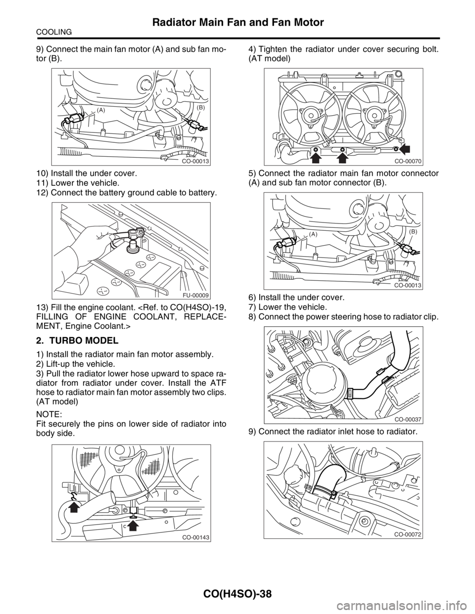
9) Connect the main fan motor (A) and sub fan mo-
tor (B).
10) Install the under cover.
11) Lower the vehicle.
12) Connect the battery ground cable to battery.
13) Fill the engine coolant.
FILLING OF ENGINE COOLANT, REPLACE-
MENT, Engine Coolant.>
2. TURBO MODEL
1) Install the radiator main fan motor assembly.
2) Lift-up the vehicle.
3) Pull the radiator lower hose upward to space ra-
diator from radiator under cover. Install the ATF
hose to radiator main fan motor assembly two clips.
(AT model)
NOTE:
Fit securely the pins on lower side of radiator into
body side.4) Tighten the radiator under cover securing bolt.
(AT model)
5) Connect the radiator main fan motor connector
(A) and sub fan motor connector (B).
6) Install the under cover.
7) Lower the vehicle.
8) Connect the power steering hose to radiator clip.
9) Connect the radiator inlet hose to radiator.
CO-00013
(A)(B)
FU-00009
CO-00143
CO-00070
CO-00013
(A)(B)
CO-00037
CO-00072
Page 1128 of 2870
![SUBARU FORESTER 2004 Service Repair Manual EN(H4SO)-30
ENGINE (DIAGNOSTIC)
Subaru Select Monitor
4. READ CURRENT DATA FOR ENGINE. (NORMAL MODE)
1) On the «Main Menu» display screen, select the {Each System Check} and press the [YES] key.
2)](/manual-img/17/57426/w960_57426-1127.png "SUBARU FORESTER 2004 Service Repair Manual EN(H4SO)-30
ENGINE (DIAGNOSTIC)
Subaru Select Monitor
4. READ CURRENT DATA FOR ENGINE. (NORMAL MODE)
1) On the «Main Menu» display screen, select the {Each System Check} and press the [YES] key.
2)")
EN(H4SO)-30
ENGINE (DIAGNOSTIC)
Subaru Select Monitor
4. READ CURRENT DATA FOR ENGINE. (NORMAL MODE)
1) On the «Main Menu» display screen, select the {Each System Check} and press the [YES] key.
2) On the «System Selection Menu» display screen, select the {Engine} and press the [YES] key.
3) Press the [YES] key after the information of engine type was displayed.
4) On the «Engine Diagnosis» display screen, select the {Current Data Display/Save}, and then press the
[YES] key.
5) On the «Data Display Menu» display screen, select the {Data Display} and press the [YES] key.
6) Using the scroll key, scroll the display screen up or down until the desired data is shown.
A list of the support data is shown in the following table.
Description Display Unit of measure
Battery voltage Battery Voltage V
Vehicle speed signal Meter vehicle speed km/h or MPH
Engine speed signal Engine speed rpm
Engine coolant temperature signal Engine coolant temperature°C or (°F)
Ignition timing signal Ignition timing deg
Throttle position signal Amount of intake air %
Throttle position signal Throttle Sensor Voltage V
Injection pulse width Fuel injection pulse width ms
Idle air control signal ISC Steps STEP
Engine load data Engine load %
Front oxygen (A/F) sensor resistance A/F sensor resistance value 1 ohm
Front oxygen (A/F) sensor output signal A/F sensor current value 1 —
Rear oxygen sensor output signalRear oxygen sensor voltage
valueV
Short term fuel trim A/F Compensation 1 %
Knock sensor signal Knock Correction deg
Atmospheric absolute pressure signal Atmospheric pressure mmHg, kPa, inHg or psi
Intake manifold relative pressure signal Mani. Relative Pressure mmHg, kPa, inHg or psi
Intake manifold absolute pressure signalIntake manifold absolute pres-
suremmHg, kPa, inHg or psi
A/F correction (short term fuel trim) by rear oxygen sensor A/F Compensation 3 %
Long term whole fuel trim A/F learning 1 %
Front oxygen (A/F) sensor heater current Front O2 heater current value A
Rear oxygen sensor heater current Rear O2 heater current value A
Canister purge control solenoid valve duty ratio CPC Valve Duty Ratio %
Fuel level signal Fuel level voltage V
Intake air temperature signal Intake air temperature°C or (°F)
Learned ignition timing Ignition learning value deg
EGR signal EGR Steps STEP
Ignition switch signal Ignition SW ON or OFF
Test mode connector signal Test mode signal ON or OFF
Neutral position switch signal Neutral SW ON or OFF
Air conditioning switch signal A/C SW ON or OFF
Air conditioning compressor signal A/C Compressor Signal ON or OFF
Radiator main fan relay signal Radiator fan relay 1 ON or OFF
Fuel pump relay signal Fuel pump relay ON or OFF
Knocking signal Knock signal ON or OFF
Radiator sub fan relay signal Radiator fan relay 2 ON or OFF
Power steering switch signal Power steering SW input signal ON or OFF
Engine torque control signal #1 AT coordinate request signal 1 ON or OFF
Engine torque control signal #2 AT coordinate request signal 2 ON or OFF
Page 1369 of 2870
FU(H4DOTC)-14
FUEL INJECTION (FUEL SYSTEM)
Intake Manifold
3. Intake Manifold
A: REMOVAL
1) Release the fuel pressure.
54, RELEASING OF FUEL PRESSURE, OPERA-
TION, Fuel.>
2) Open the fuel filler flap lid and remove the fuel
filler cap.
3) Disconnect the ground cable from battery.
4) Lift-up the vehicle.
5) Remove the under cover.
6) Drain the coolant about 3.02 (3.2 US qt, 2.6 Imp
qt).
7) Remove the air cleaner upper cover and air in-
take boot.
Cleaner.>
8) Remove the air cleaner element.
9) Remove the intercooler.
10, REMOVAL, Intercooler.>
10) Disconnect the accelerator cable.
11) Remove the coolant filler tank.
CO(H4SO)-42, REMOVAL, Coolant Filler Tank.>
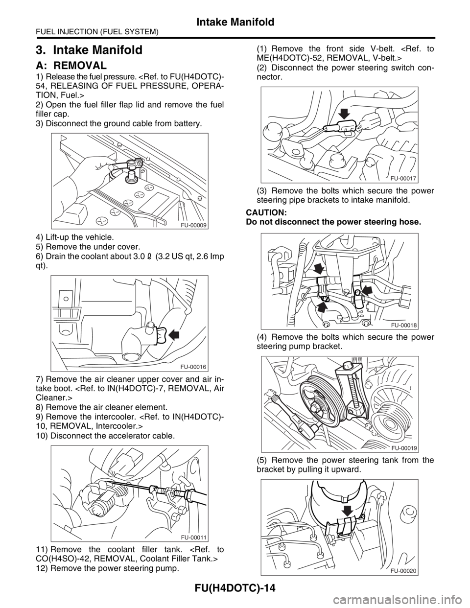
12) Remove the power steering pump.(1) Remove the front side V-belt.
ME(H4DOTC)-52, REMOVAL, V-belt.>
(2) Disconnect the power steering switch con-
nector.
(3) Remove the bolts which secure the power
steering pipe brackets to intake manifold.
CAUTION:
Do not disconnect the power steering hose.
(4) Remove the bolts which secure the power
steering pump bracket.
(5) Remove the power steering tank from the
bracket by pulling it upward.
FU-00009
FU-00016
FU-00011
FU-00017
FU-00018
FU-00019
FU-00020
Page 1370 of 2870
FU(H4DOTC)-15
FUEL INJECTION (FUEL SYSTEM)
Intake Manifold
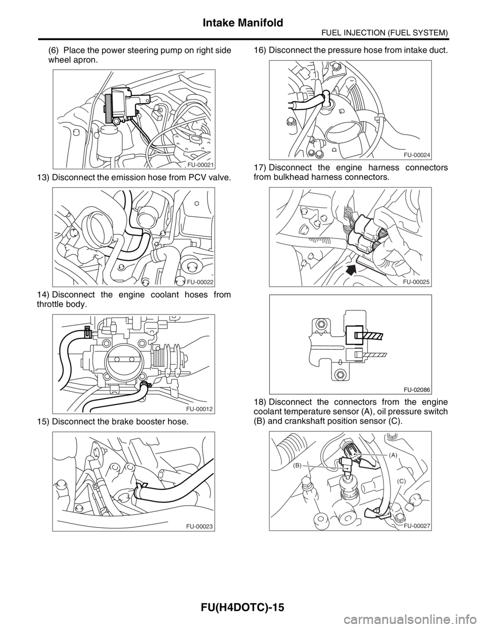
(6) Place the power steering pump on right side
wheel apron.
13) Disconnect the emission hose from PCV valve.
14) Disconnect the engine coolant hoses from
throttle body.
15) Disconnect the brake booster hose.16) Disconnect the pressure hose from intake duct.
17) Disconnect the engine harness connectors
from bulkhead harness connectors.
18) Disconnect the connectors from the engine
coolant temperature sensor (A), oil pressure switch
(B) and crankshaft position sensor (C).
FU-00021
FU-00022
FU-00012
FU-00023
FU-00024
FU-00025
FU-02086
(A)
(B)
(C)
FU-00027
Page 1374 of 2870
FU(H4DOTC)-19
FUEL INJECTION (FUEL SYSTEM)
Intake Manifold
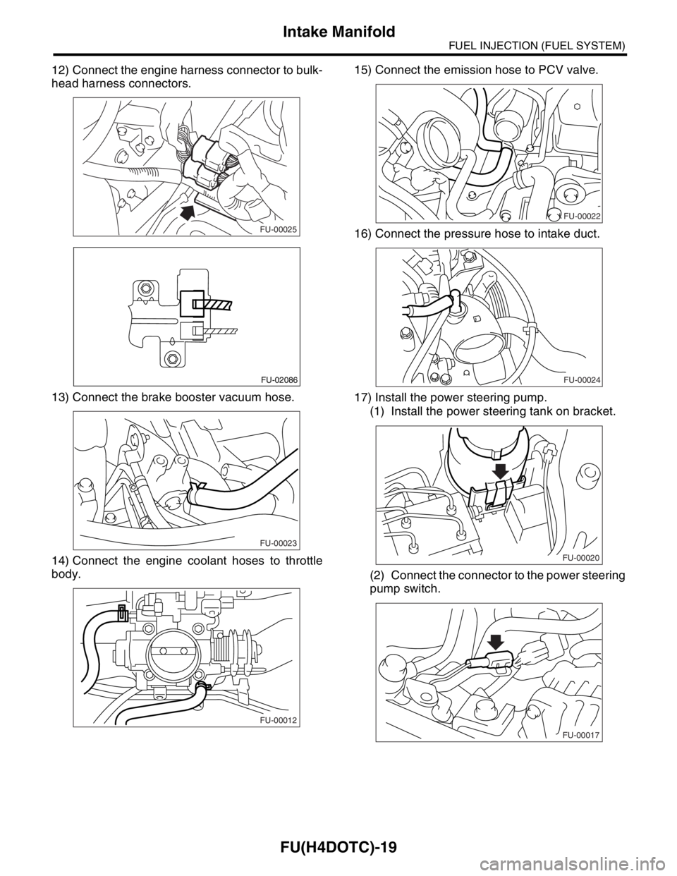
12) Connect the engine harness connector to bulk-
head harness connectors.
13) Connect the brake booster vacuum hose.
14) Connect the engine coolant hoses to throttle
body.15) Connect the emission hose to PCV valve.
16) Connect the pressure hose to intake duct.
17) Install the power steering pump.
(1) Install the power steering tank on bracket.
(2) Connect the connector to the power steering
pump switch.
FU-00025
FU-02086
FU-00023
FU-00012
FU-00022
FU-00024
FU-00020
FU-00017
Page 1375 of 2870
FU(H4DOTC)-20
FUEL INJECTION (FUEL SYSTEM)
Intake Manifold
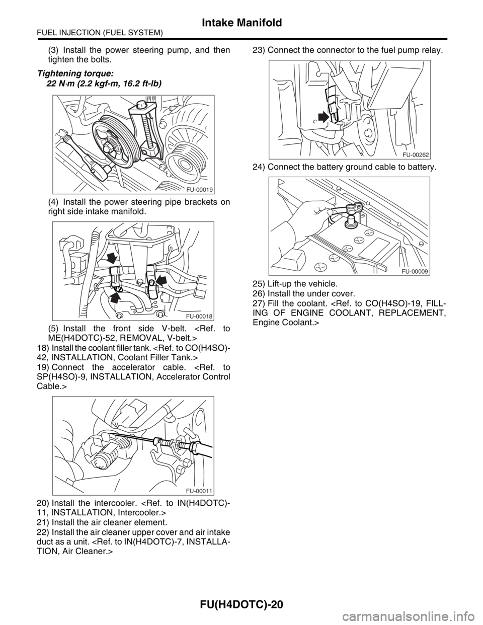
(3) Install the power steering pump, and then
tighten the bolts.
Tightening torque:
22 N
⋅m (2.2 kgf-m, 16.2 ft-lb)
(4) Install the power steering pipe brackets on
right side intake manifold.
(5) Install the front side V-belt.
ME(H4DOTC)-52, REMOVAL, V-belt.>
18) Install the coolant filler tank.
42, INSTALLATION, Coolant Filler Tank.>
19) Connect the accelerator cable.
SP(H4SO)-9, INSTALLATION, Accelerator Control
Cable.>
20) Install the intercooler.
11, INSTALLATION, Intercooler.>
21) Install the air cleaner element.
22) Install the air cleaner upper cover and air intake
duct as a unit.
TION, Air Cleaner.>23) Connect the connector to the fuel pump relay.
24) Connect the battery ground cable to battery.
25) Lift-up the vehicle.
26) Install the under cover.
27) Fill the coolant.
ING OF ENGINE COOLANT, REPLACEMENT,
Engine Coolant.>
FU-00019
FU-00018
FU-00011
FU-00262
FU-00009
Page 1500 of 2870
ME(H4DOTC)-42
MECHANICAL
Engine Assembly
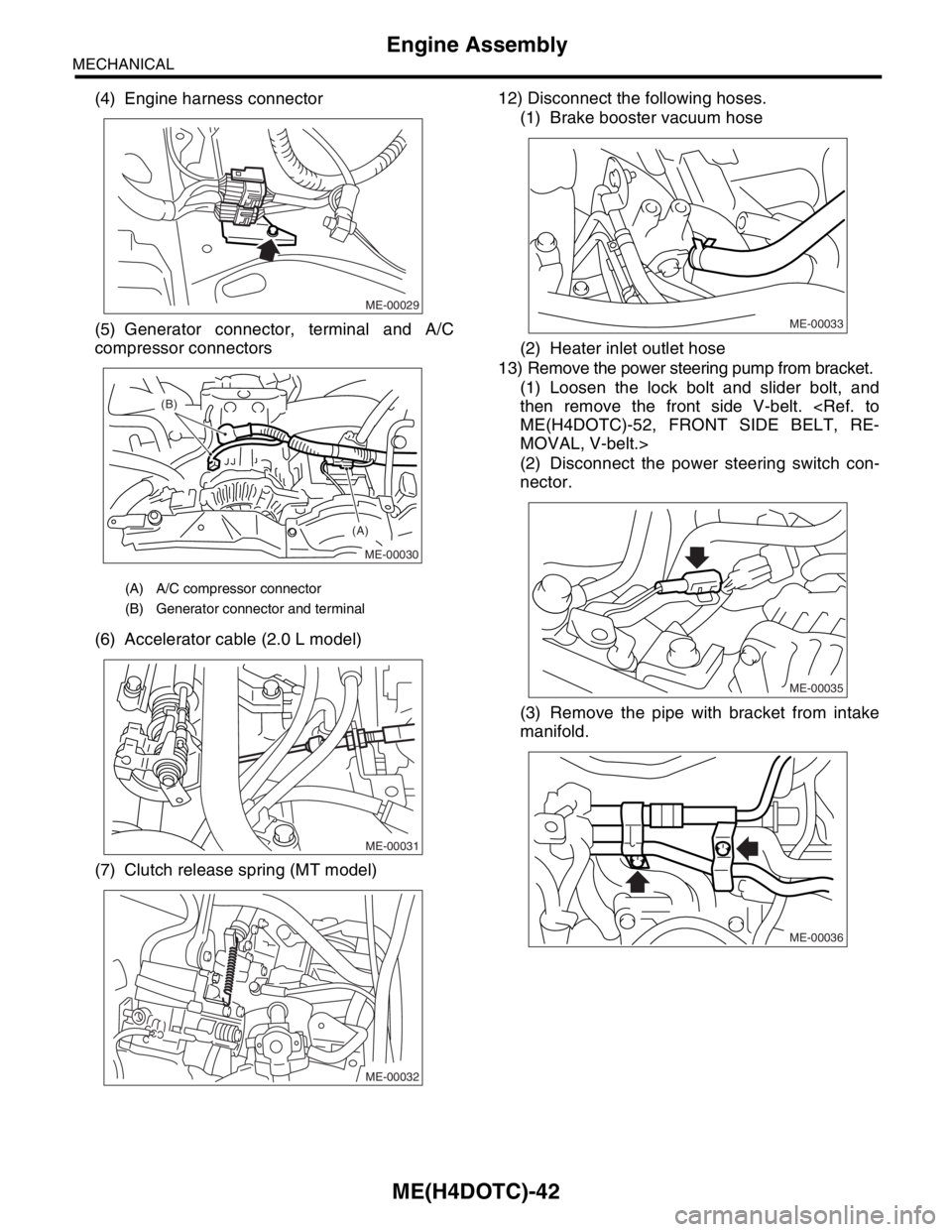
(4) Engine harness connector
(5) Generator connector, terminal and A/C
compressor connectors
(6) Accelerator cable (2.0 L model)
(7) Clutch release spring (MT model)12) Disconnect the following hoses.
(1) Brake booster vacuum hose
(2) Heater inlet outlet hose
13) Remove the power steering pump from bracket.
(1) Loosen the lock bolt and slider bolt, and
then remove the front side V-belt.
ME(H4DOTC)-52, FRONT SIDE BELT, RE-
MOVAL, V-belt.>
(2) Disconnect the power steering switch con-
nector.
(3) Remove the pipe with bracket from intake
manifold.
(A) A/C compressor connector
(B) Generator connector and terminal
ME-00029
ME-00030
(A) (B)
ME-00031
ME-00032
ME-00033
ME-00035
ME-00036
Page 1501 of 2870
ME(H4DOTC)-43
MECHANICAL
Engine Assembly
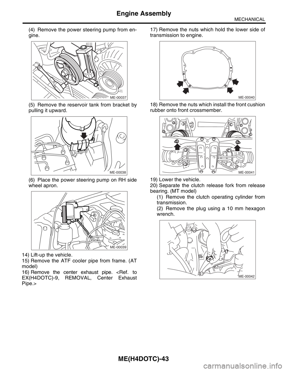
(4) Remove the power steering pump from en-
gine.
(5) Remove the reservoir tank from bracket by
pulling it upward.
(6) Place the power steering pump on RH side
wheel apron.
14) Lift-up the vehicle.
15) Remove the ATF cooler pipe from frame. (AT
model)
16) Remove the center exhaust pipe.
EX(H4DOTC)-9, REMOVAL, Center Exhaust
Pipe.>17) Remove the nuts which hold the lower side of
transmission to engine.
18) Remove the nuts which install the front cushion
rubber onto front crossmember.
19) Lower the vehicle.
20) Separate the clutch release fork from release
bearing. (MT model)
(1) Remove the clutch operating cylinder from
transmission.
(2) Remove the plug using a 10 mm hexagon
wrench.
ME-00037
ME-00038
ME-00039ME-00040
ME-00041
ME-00042